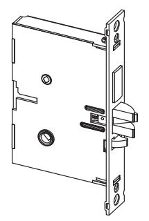
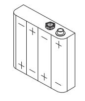
EPlex 5×00 Installation Instruction for 1 Inch Mortise
Open the original PDF document
View PDF
BEYOND SECURITY

E-PLEX ®
1" MORTISE INSTALLATION INSTRUCTIONS
TABLE OF CONTENTS
| Tools | Required3 |
|---|---|
|
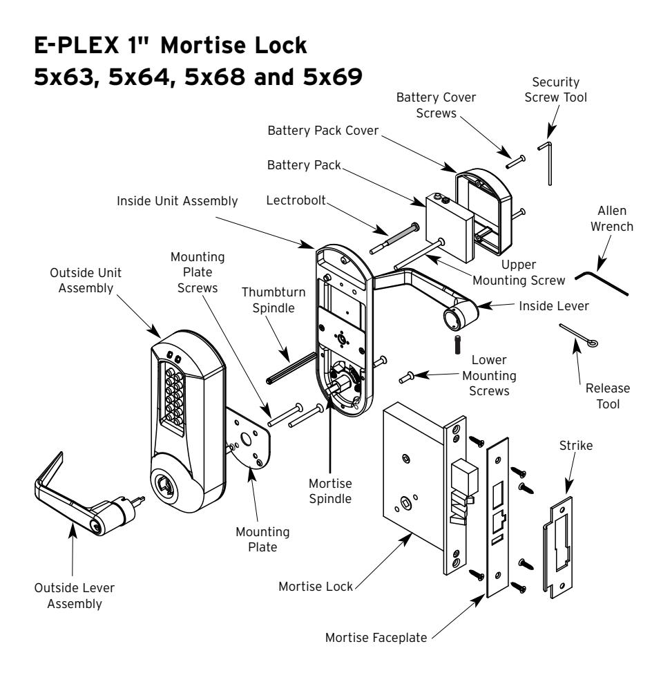
Exploded
Install Parts4 |
|
|
Handing
Diagram5 |
|
| A. |
Mortise
Handing5 |
| B. |
Door
Preparation6 |
| C. |
Installing
the Strike7 |
| D. |
Installing
Outside Unit Assembly8 |
| E. |
Installing
Inside Unit Assembly9 |
| F. |
Installing
the Inside Lever9 |
| G. |
Changing
Key-In-Lever Cylinder10 |
| H. |
Installing
/ Removing Outside Lever (Key-In-Lever) KIL11 |
| I. |
Installing
/ Removing Outside Lever (Interchangeable/11 |
|
removable
core models) |
|
| J. |
Installing
the Battery Pack and Cover13 |
| K. |
Testing
the Operation of the Lock14 |
| L. |
Programming
and Software Settings14 |
| M. |
Installing
Rubber Bumpers15 |
Warning
The Master Code of this lock has been factory preset: 1,2,3,4,5,6,7,8. To activate lock functions, the master combination must be changed at time of installation.
Warnings and Cautions
Important : Carefully inspect windows, door frame, door, lights, etc. to ensure that the recommended procedures will not cause damage. Kaba Access Control's warranty does not cover damages caused by installation.
Caution : Wear safety glasses when preparing door.
Introduction
The purpose of this manual is to instruct the installer on the proper installation procedure for the E-Plex 5x63, 5x64, 5x68 and 5x69 1" American Steel Mortise (ASM) Mortise locks. These instructions pertain to models with and without deadbolts. For models without deadbolts, please disregard any references to a thumbturn in the instructions.
OPERATIONAL NOTE:
The E-Plex Mortise lock is almost identical to the E-Plex 5000 Cylindrical lock with the following exceptions:
- 1. Operation of the Lever When the lock's handing is properly set, only a downward rotation of lever will actuate latch.
- 2. Key Override Use The key override differs in that rotating the key does not actuate the latch. To use the key override the key must be inserted into the cylinder and rotated counter clockwise until it stops (approximately 90 degrees) then while holding the key in this position with one hand use the other hand to rotate the lever downward to retract the latch. Once the lever has rotated a few degrees the key may be released.
TOOLS REQUIRED
- Safety glasses
- 1 ⁄2" (13 mm) chisel
- 1 ⁄8" (3 mm) drill bit
- 1 ⁄4" (7 mm) drill bit
- 1 ⁄2" (13 mm) drill bit
- 21 ⁄8" (54 mm) hole saw
- Drill
- Awl or center punch
- Hammer
- Small flat screwdriver
- Phillips screwdriver (#2)
- Fine steel file
- Mortising machine
- Router
- Mortise faceplate router template
- Adjustable square
- Tape measure
- Pencil
- Tape
- Cleaning supplies (drop cloth, vacuum)
INSTALLATION QUALIFICATIONS
These instructions are designed for use by maintenance professionals or lock installers who are familiar with common safety practices and competent to perform the steps described. Kaba Access Control is not responsible for damage, injury or malfunction due to incorrect installation.

For technical assistance please call 1-800-849-TECH (8324) or 336-725-1331
Handing Diagram
To determine handing, face the door from the exterior (access) side and select the corresponding diagram below.
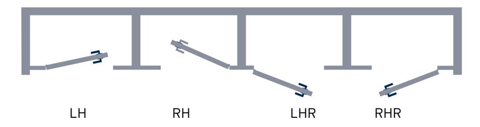
Chart
|
Model
Number |
Handing | Deadbolt |
|---|---|---|
| E5x63 | LH/RHR | No |
| E5x64 | RH/LHR | |
| E5x68 | LH/RHR | |
| E5x69 | RH/LHR | Yes |
A. MORTISE HANDING
The 1" Mortise is not field reversible. You must have the appropriate model for the door handing of the installation.
For LH (left hand) and RHR (right hand reverse)
For RH (right hand) and LHR (left hand reverse)
B. DOOR PREPARATION
If using the installation jig to prepare the door, refer to the instructions provided with the jig, then proceed with step 7.
B-1 Mark the handle height on the edge of the door, as determined directly from the strike.
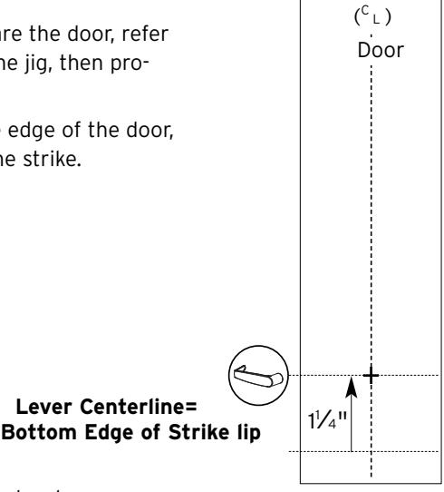
The axis of rotation of the handle is level with the bottom lip of the strike.
- B-2 Align the template along the vertical center line of the mortise (CL) at the desired handle height, and tape it to the door.
- B-3 Mark all holes and cutouts for the mortise in the edge of the door and remove the template.
- B-4 Locate the two sets of vertical fold lines on the template allowing you to adjust the positioning of the template depending on the bevel of the door.
Note : Fold lines on template are for 1 3⁄8" door. Some thickness and bevel conditions may make it necessary to re-position the template for marking each side of the door.
B-5 If the door has no bevel, fold the template along the solid lines. Align the fold with the edge of the door and mark the holes for the lock.
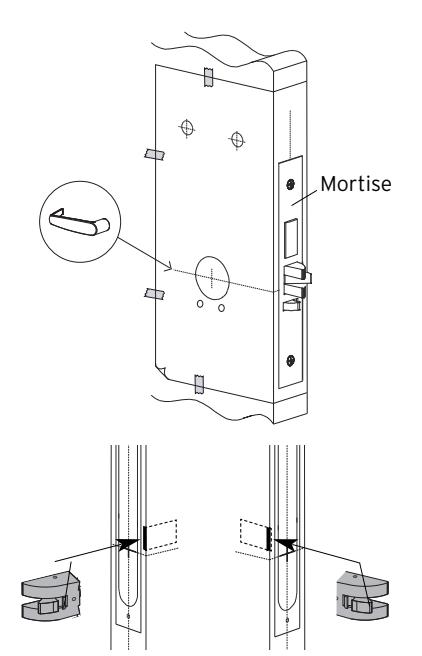
RH/LHR (ASM shown) LH/RHR
Repeat on the other side of the door. If the door has a 3° bevel, fold and align the dashed line marked "H" on the template with the higher-beveled edge of the door and mark the lock holes on that side of the door. Repeat on the side with the lower-beveled edge using the dashed line marked "L."
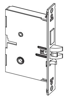
- B-6 Prepare the cutout for the mortise in the edge of the door using a mortising machine, router and chisel (for dimensions, refer to template). Ensure clearance is provided for moving latch parts as indicated on the template.
- B-7 When making holes, drill from both sides of the door to prevent unsightly damage (for dimensions, refer to template). Drill the small holes before the large holes. This will keep small holes on location before the 2 1 ⁄8" holes are made tangent with them.
- B-8 Check the bevel of the mortise faceplate. If adjustment is required, loosen the two bevel screws (R) and adjust mortise front plate angle to match the bevel of the door.
- B-9 Re-tighten screws.
- B-10 Install the mortise with two 1" Phillips screws (Q) provided.
- B-11 Install mortise faceplate (P) with the two 8-32 x 1 ⁄4" screws provided.
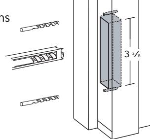
C. INSTALLING THE STRIKE
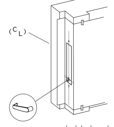
C-1 Align the paper template on the door frame to match with the desired handle height, and along the vertical center line of the mortise (CL), which is also the center line of the door, allowing for any bumpers on the door frame.
Respect applicable building codes regarding handle height.
P
Q
R
R
Logo
C-2 Select the strike for the desired handing, according to the depiction on the template. Mark the location of the strike cutout and mounting screws.
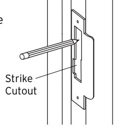
C-3 Drill pilot holes for the strike mounting screws. Mortise the door frame for the strike dimensions shown. 3 3⁄8" (L) X 1" (D) X 1" (W)
Note : Make certain not to mortise over screw holes drilled earlier.
C-4 Position the strike against the door frame and align it with the mounting screw holes. Then mark the outline of the strike.
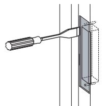
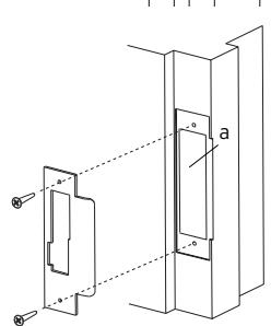
- C-5 Remove any material from within the strike outline (a) so that the strike will be flush with the door frame.
- C-6 Install the strike using the screws provided.
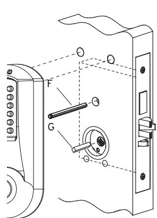
D. INSTALLING OUTSIDE UNIT ASSEMBLY
Note : Ensure that the mounting hole for the red collars is cleaned out so that the collars are not crushed upon installation. If necessary, the hole can be opened up to 5⁄16".
- D-1 For door thickness of 1 3⁄8", insert the square spindle (G) into the outside housing hub.
- D-2 If your lock comes with a thumbturn, insert the end (with the ring groove) of the thumbturn spindle (F) into the small spindle hole in the outside housing.
- D-3 Place the outside housing on the door so that the bottom spindle engages the hub on the mortise, and the top thumbturn spindle passes through the mortise top hub. The outside unit assembly (c) will rest flush against the door. Ensure the red collar is seated into the top left mounting hole.
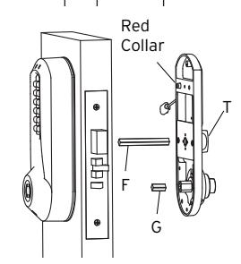
E. INSTALLING INSIDE UNIT ASSEMBLY
E-1 Place inside mounting plate flush against the door as shown. For a door thicknesses of 1 3⁄8" insert diagonally (as shown) two 1 1 ⁄2" Phillips flat head screws (supplied in parts door kit).
Note : The screws must correspond to the two through holes in the mortise.
- E-2 Insert the square spindle (G) into the inside housing hub.
- E-3 Put the thumbturn (T), if applicable in a vertical position and place the inside trim assembly on the door so that the upper spindle (F) engages the thumbturn and mortise hubs, respectively. Ensure the red collar is seated into its mounting hole. Carefully push the inside housing flush against the door.
C
E-4 Supplied hardware should correspond to the chart below:
|
Door
Thickness |
LectroBolt
Size |
Top
Mounting Screw Size |
Lower
Mounting Screws |
|---|---|---|---|
|
1
3⁄8" |
2
3⁄8" |
2
⁄2" 1 |
5⁄8" |
|
(35
mm) |
(60
mm) |
(64
mm) |
(16
mm) |
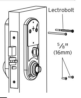
- E-5 Insert the LectroBolt™ through the red inside housing hole marked with the lightening bolt symbol. For now, only partially tighten the LectroBolt™ to keep the red collars in position.
- E-6 Then, insert and tighten the other three mounting screws. (Refer to the chart for correct screw lengths.)
- E-7 Finish tightening the LectroBolt™ to secure the lock on the door.
Warning : If using a power drill, please be careful not to over-tighten as this could cause damage to the mounting

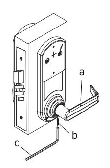
F. INSTALLING THE INSIDE LEVER
Insert the inside lever (A) onto the inside unit assembly. Secure the inside lever with the hex screw (B) (supplied) using the allen wrench (C) (supplied).
KABA E-PLEX® 5x00 SERIES LIMITED WARRANTY
Kaba Access Control warrants this product to be free from defects in material and workmanship under normal use and service for a period of three (3) years. Kaba Access Control will repair or replace, at our discretion, 5000 Series Locks found by Kaba Access Control analysis to be defective during this period. Our only liability, whether in tort or in contract, under this warranty is to repair or replace products that are returned to Kaba Access Control within the three (3) year warranty period.
This warranty is in lieu of and not in addition to any other warranty or condition, express or implied, including without limitation merchantability, fitness for purpose or absence of latent defects.
ATTENTION: This warranty does not cover problems arising out of improper installation, neglect or misuse. All warranties implied or written will be null and void if the lock is not installed properly and /or if any supplied component part is substituted with a foreign part. If the lock is used with a wall bumper, the warranty is null and void. If a doorstop is required, we recommend the use of a floor secured stop.
The environment and conditions of use determine the life of finishes on Kaba Access Control products. Finishes on Kaba Access Control products are subject to change due to wear and environmental corrosion. Kaba Access Control cannot be held responsible for the deterioration of finishes.
Authorization to Return Goods
Returned merchandise will not be accepted without prior approval. Approvals and Returned Goods Authorization Numbers (RGA Numbers) for the 5000 Series are available through our Customer Service department in Winston-Salem, NC (800) 849-8324. The serial number of a lock is required to obtain this RGA Number . The issuance of an RGA does not imply that a credit or replacement will be issued.
The RGA number must be included on the address label when material is returned to the factory. All component parts including latches and strikes (even if not inoperative) must be included in the package with return. All merchandise must be returned prepaid and properly packaged to the address indicated.
* Simplex 5000 locks are warranted three (3) years from date of purchase. E-Plex 5x00 locks are warranted three (3) years from date of activation.

NO POSTAGE NECESSARY IF MAILED IN THE UNITED STATES

BUSINESS REPLY MAIL FIRST-CLASS MAIL PERMIT NO. 1563 WINSTON-SALEM, NC
POSTAGE WILL BE PAID BY ADDRESSEE
KABA ACCESS CONTROL 2941 INDIANA AVENUE WINSTON-SALEM, NC 27199-3770
REGISTRATION CARD
This lock will be used in what type of
facility?
Thank you for purchasing our product. In order protect your investment and to enable us to serve you in the future, please fill out this card and return it to Kaba Access Control, or register online
Name Position Company Address
City State
Phone Email Name of
Date of
Lock
Model
|
Ac
ce ss Co nt ro l loc ks |
in
fo rm at io n on Ka ba |
ul
d lik e m or e |
wo |
o
Ch ec k he re if |
|||
|---|---|---|---|---|---|---|---|
|
o
Ot he r |
Ma
int en an ce |
o |
o
Lo ck sm ith |
Nu
m be r |
|||
|
ur
loc k? |
W
ho in st al led yo |
ha
se |
Pu
rc |
||||
|
ale
r Pu rc ha se d Fr om |
De | ||||||
|
loc
k? |
fo
r bu yi ng th is |
re
as on |
W
ha t wa s yo ur |
||||
|
o
Ot he r (p lea se sp ec ify ) |
o
Tr ai ni ng Cl as s |
Ma
int en an ce |
o |
o
Lo ck sm ith |
|||
|
Lo
o ck s? An ot he r Us e |
Co
o nt Int ro l er Pu ne sh t / bu W tt eb on |
Pr
Ka ev io ba us Ac Us ce e ss |
rn
t ab o ou t |
o
Ho w Ad di ve d rti yo se u m lea en |
Co
un tr y |
ZI
P (P os ta l Co de ) |
|
|
Ka
ba |
Lo
ck ot he r th an |
Ke
yle ss |
o
Re pla cin g a |
||||
|
Co
nt ro l |
ct
ro nic Ac ce ss |
Ka
ba Ele |
o
Re pla cin g a |
||||
|
tto
n Lo ck |
ch
an ica l Pu sh bu |
Ka
ba Me |
o
Re pla cin g a |
||||
|
na
l ke ye d loc k |
co
nv en tio |
o
Re pla cin g a |
|||||
|
tio
n |
o
Ne w Ins ta lla |
||||||
|
Th
is loc k is: |
|||||||
|
Co
m m on Do or , Ex er cis e Ro om ) |
loc
k? (e .g. Fr on t Do or , |
re
d wi th th is |
in
g se cu |
W
ha t ar ea is be |
|||
|
.c
nt om ro l, or |
lin
tu e rn at it w to w w. Ka ka ba ba Ac ac ce ce ss ss Co |
on
re |
|||||
|
lea
se sp ec ify ) |
o
Ot he r (p |
alt
hc ar e |
o
Ho sp ita l/ He |
th
is re gi st ra tio n |
in
th e fu tu re , pl ea se fil l ou t |
||
|
Sc
ho ol /E du ca tio na l |
m
en t/ Mi lita ry o |
o
Go ve rn |
er
sit y |
o
Co lle ge /U niv |
le
us to be tt er |
ur
in ve st m en t an d to en ab |
yo |
|
Ai
rp or t |
al
/ Ma nu fa ct ur ing o |
o
Ind us tri |
Bu
ild ing |
o
Co m m er cia l |
uc
t. In or de r to |
fo
r pu rc ha si ng ou r pr od |
yo
u |
here if you would like more
| Notes | |
|---|---|
G. CHANGING KEY-IN-LEVER CYLINDER
On key-in-lever models of the E-Plex 5000 series, the outside lever comes preassembled with Kaba's key-in-lever cylinder (Kaba 1599). To use a different key-in-lever cylinder follow remaining steps in this section.
G-1 To remove KIL (key-in-lever) cylinder (a) from the outside lever (b). Remove the cylinder insert (e) and the cylinder retainer (c) using a small flat bladed screwdriver or small needle nose pliers.
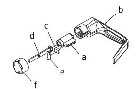
G-2 Determine the proper tailpiece (d) from the chart below for your KIL cylinder.
You must use a Kaba tailpiece. The K 2 tailpiece is preassembled with the Kaba 1599.
| TAILPIECE |
KIL
CYLINDER |
|---|---|
| K1 |
Abloy
5277, Abloy 5477, Assa 65691, Kaba 1539, Kaba Gemini 4730 |
| K2 |
Assa
65611, Australian: Kaba expert 107K5 & Boyd KC286, Corbin-Russwin 2000-03, Kaba 1599, Schlage 23-001, Schlage Primus 20-760, Kaba Peaks 1099 |
| K3 |
Medeco
20W200H1 |
| K4 |
Arrow
C100, Sargent 10 LINE |
| K5 | Marks |
G-3 Assemble the required tailpiece (d) (from above) with your KIL cylinder. All tailpieces must be installed vertically (with key removed from cylinder) for proper installation.
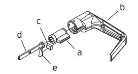
G-4 Insert the KIL cylinder (a) into the outside lever and secure it with the cylinder retainer (c) and the cylinder insert (e) until the KIL cylinder is snug and unable to move freely.
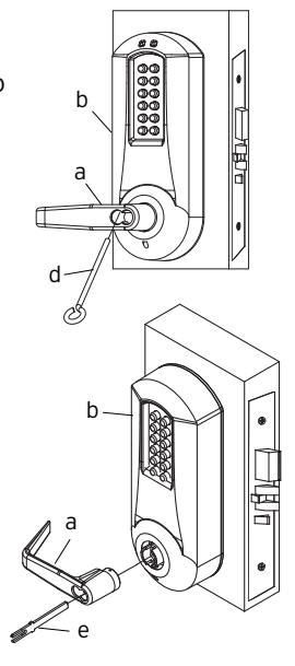
H. INSTALLING / REMOVING OUTSIDE LEVER
(Key-In-Lever models only)
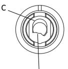
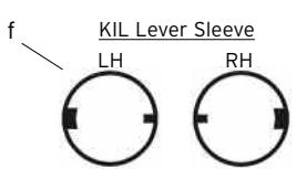
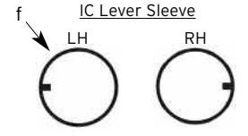
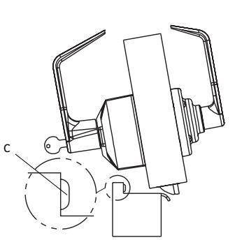
H-1 Make certain the lever catch is up as shown (c). To successfully install the outside lever, the lever sleeve (f) tab must be positioned correctly with the respective notch on the lever. The lock comes shipped with the lever sleeve already installed in the lock housing. When installing lever, ensure it is oriented to engage the lever sleeve to accommodate desired lock handing as shown.
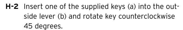
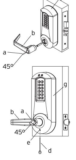
H-3 Insert the outside lever (b) until it is flush to the outside unit assembly (g). Secure the outside lever by rotating the key (a) clockwise 45 degrees to horizontal position. Remove key.
Note : To remove the outside lever from the outside unit assembly, follow the step below.
H-4 Insert one of the supplied keys (a) into the outside lever and rotate it counterclockwise 45 degrees. Insert release tool (d) into the small hole (e) under lever as shown. Gently push lever catch up until it clicks. Remove tool, then remove outside lever (b).

g
I. INSTALLING / REMOVING OUTSIDE LEVER
(Interchangeable / Removable Core Models)
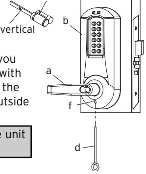
I-1 Make certain the lever catch is up as shown (c). To successfully install the outside lever, the lever sleeve (f) tab must be positioned correctly with the respective notch on the lever. The lock comes shipped with the lever sleeve already installed in the lock housing. When installing lever, ensure it is oriented to engage the lever sleeve to accommodate desired lock handing as shown.
Note : For all interchangeable/removable cylinders except ASSA/Medeco/Yale, proceed to section I-2. For ASSA/Medeco/Yale cylinders, skip to section I-5.
Position
Position
- I-2 Insert the outside lever (a) until it is flush to the outside unit assembly (b). To secure the outside lever, insert the release tool (d) (or screwdriver) into the outside lever as shown, and slide the lever catch down until it clicks. Make certain lever is attached before installing the core.
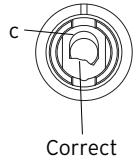
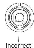
- I-3 Insert the supplied tailpiece (e) vertically into the outside lever as shown. Make certain that you rotate the tailpiece so that it will align with the interchangeable core. For screw cap type cylinders (Schlage) (g), the tailpiece must be assembled to the cylinder first as shown (vertical position). Insert the interchangeable core into the outside lever.
Note : To remove the outside lever from the outside unit assembly, follow steps below.
- I-4 Remove the interchangeable core (g). Then remove the tailpiece (e).
- I-5 For ASSA/Medeco/Yale interchangeable/removable cylinders, the tailpiece must be prepped for the desired length before installation.
When using a Yale cylinder on a cylindrical latch application, measure the door thickness of the intended application.
- I-6 Notice the score marks on the flat portion of the ASSA/Medeco/Yale tailpiece. Using the diagram to the right, locate the score mark on your tailpiece that matches your cylinder prep for the intended application, and break the tailpiece off accordingly.
- I-7 Using 2 pairs of pliers, break the tailpiece to the desired length of the intended application by holding 1 pair of pliers on the good side of the score mark and one pair on the other side of the score mark. Slowly move the 2nd pair of pliers up and down until the unneeded portion of the tailpiece breaks free.
- I-8 Insert the Medeco tailpiece (e) vertically into the outside lever as shown. Make certain that you rotate the tailpiece slightly so that it will align with the interchangeable/removable cylinder. Insert the interchangeable/removable cylinder into the outside lever.
Note : To remove the outside lever from the outside unit assembly, follow steps below.
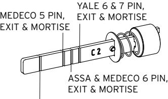
YALE 6 & 7 PIN, CYLINDRICAL – THIN DOOR (1 3⁄8" (35 mm) to 1 1 ⁄2" (38 mm)) (DO NOT SHORTEN TAILPIECE - For 1 5⁄8" (41 mm) to 2 1 ⁄4" (57 mm))
ASSA/MEDECO 5, 6 & 7 PIN, CYLINDRICAL – DO NOT SHORTEN TAILPIECE
g
I-9 Remove the interchangeable/removable cylinder. Then remove the tailpiece (e).
Note : You may want to use needle nose pliers for some tailpieces.
I-10 Insert the lever release tool (d) into the small hole (f) under lever as shown. Gently push lever catch up until it clicks. Remove tool, then remove outside lever (a).
Note : You may want to use needle nose pliers for some tailpieces.
Insert the release tool (d) into the small hole (f) under the lever as shown. Gently push lever catch up until it clicks. Remove tool, then remove the outside lever (a).
Note: Do not shut door until installing batteries and testing operation as outlined in the following two sections.
J. INSTALLING THE BATTERY PACK AND COVER/CHANGING BATTERIES
J-1 To install the battery pack (f) and cover (g), snap the cable connector onto the top of the loaded battery pack. Then place the battery pack into the cover, terminals at the top. Put the two security screws (h) into the cover and fasten the cover to the inside housing with the security screw tool (i).
Caution : Over-tightening these screws could strip h i
the threads in the housing or crack the cover.
Warning : If the lock goes without power for more than two minutes, you will lose the lock's current date and time only. If this happens, program the lock with the correct date and time. Refer to Operations Manual.
- J-2 Remove the two screws (h) securing the battery cover to the housing, using the security screw tool (i) provided with your lock.
- J-3 Remove the four depleted batteries and install four new Alkaline only AA batteries. Ensure that each battery is installed in the proper direction as shown at each battery location in the battery holder (f).
f
g
Warning : Do not install a 9V battery. Your lock operates on 4 alkaline only AA batteries (6V). A 9V will ruin the electronics in the lock, and void your warranty!
J-4 Reconnect the battery cable. Place the battery holder into the cover. Screw the back cover onto the inside housing, ensuring that the cable is not trapped under the edge of the cover.
Caution : Over-tightening these screws could strip the threads in the housing or crack the cover.
K. TESTING THE OPERATION OF THE LOCK
- K-1 Rotate inside lever and hold. Ensure that the mortise latch is fully retracted and flush with the mortise faceplate. Release the inside lever; the latch should be fully extended.
- K-2 Enter the factory-set combination: 1,2,3,4,5,6,7,8. You should see a green light and hear a high-pitched tone as you push each button. When the lock opens you will briefly hear the sound of an electric motor. If 1,2,3,4,5,6,7,8 does not seem to work, please follow the steps to perform a hard reset by following the procedure in section L.
- K-3 Rotate outside lever and hold. Ensure that the latch is fully retracted and flush with the latch faceplate. Release the outside lever; the latch should be fully extended. When the lock re-locks, you will again hear the motor.
- K-4 Insert key into the outside lever. Rotate key counterclockwise to stop position and hold. Ensure that the latch is fully retracted and flush with the latch faceplate. Rotate the key clockwise to the horizontal position and remove the key. The latch should be fully extended.
- K-5 To test the deadbolt function (where applicable), turn the thumbturn knob to extend the deadbolt. A red light should flash once. Then, turn the thumbturn again and verify that the deadbolt is retracted and there is a flash of the green light.
Note : Refer to the Operating Manual to set up lock operation.
L. PROGRAMMING AND SOFTWARE SETTINGS:
- L-1 You must change the master Code from the factory default to another code to program the lock. For further information on how to manually program the E-Plex 3x00/5x00 Series Models, refer to the companion "E-Plex 3x00/5x00 Operation Manual." Software is required to program the E3200/E5200 Series Locks.
- L-2 When configuring the E3000/E5000 Series Locks using the optional Standard Software, choose the box that contains "Entry Lock with Passage (Cylindrical or Mortise without Deadbolt)" during lock setup.
- L-3 When configuring the E3200/3700 and E5200/E5700 Series Locks using the Enterprise Software, select the appropriate lock type during lock setup. .
M. INSTALLING RUBBER BUMPERS
M-1 Close the door and apply pressure making sure the deadlatch (a) rests on the strike plate (b) as shown. Standing on the frame (door step) side of the door, check for gaps between the door and the frame on the three sides of the frame (left, right and top).
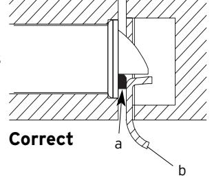
M-2 Mark locations where the gaps are approximately 3⁄16" (5 mm). Make sure these locations are free from grease and dust. Peel the bumpers (c) (supplied) from their protective backing without touching the adhesive surface and stick them on the marked locations.
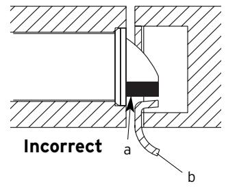
Note : Allow 24 hours for bumper adhesive to set before testing. The door may be operated manually during this time.

Kaba Access Control 2941 Indiana Avenue Winston-Salem, NC 27105 USA Tel: (800) 849-8324 (336) 725-1331 Fax: (800) 346-9640 (336) 725-3269