EP499 Control Station For Use In Hazardous Locations Installation Instructions
Open the original PDF document
View PDF

801 Avenida Acaso, Camarillo, Ca. 93012 • (805) 494-0622 • www.sdcsecurity.com • E-mail: service@sdcsecurity.com
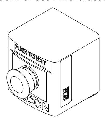
INSTALLATION INSTRUCTIONS MODEL: EP499 Control Station For Use In Hazardous Locations
General Safety Information:
CAUTION:
Before installing, make sure you are compliant with all and area classifications. Failure to do so may result in bodily injury, death and property damage. Do not attempt installation until you are familiar with the following procedures. All installation must comply with the applicable Electrical Code.
Make sure that the circuit is de-energized before starting installation or maintenance.
Verify that the installation is ground. Failure to ground will create electrical shock hazards, which can cause serious injury and or death.
IMPORTANT:
Please read these instructions carefully before installing or maintaining this equipment. Good electrical practices should be followed at all times and this data should be used as a guide only.
Technical information, advice and recommendations contained in these documents is based upon information Security Door Controls believes to be reliable. All the information and advice contained in these documents is intended for persons having been trained and possessing the requisite skill and know-how and to be used by such persons only at their own discretion and risk. The nature of these instructions is informative only and does not cover all of the details, variations or combinations in which this equipment may be used, it' s storage, delivery, installation, check-out, safe operation and maintenance.
Since conditions of use of the product are outside of the care, custody and control of Security Door Controls, the purchaser should determine the suitability of the product for his intended use, and assumes all risk and liability whatsoever in connection therewith.
INSTALLATION INSTRUCTIONS
a) Remove the cover retaining screws. Install the back box of the control station securely to a flat surface with screws that fit the 0.24 diameter hole or slot without damaging them. If needed, washers are permitted.
The enclosures are molded with "TOP" on the inside of the cover and the back of the box. For convenience, the back of the box has mounting dimensions molded into the back surface.
- b) Install the conduit or cable to the box using fitting that are certified as suitable for the area classification and service environment.
- c) Connect conductors to the component terminals.
Note: Normally-Open Contact Block has a white terminal housing, and is labeled "NO". Normally-Closed Contact Block has a grey terminal housing, and is labeled "NC".
Follow all wire stripping and terminal torque instructions for each component as described on the contact blocks.
Grounding connections are available at the din rail and hub locknut.
- d) Perform a continuity check to ensure the circuit is wired properly for the intended use.
- e) Before replacing the cover, ensure all wires are neatly installed within the control station base and are well away from the lid base joint and gasket area.
Replace the enclosure cover making note of "TOP" molded inside the cover. Thread each cover screw half way into the threaded insert without completely tightening. Snug the screws down in a diagonal pattern but don't overtighten.
DO NOT OVERTIGHTEN OR USE AN IMPACT TOOL.
A consistent fit over the entire length of the cover joint should be verified at the time of installation.
f) Turn the supply circuit and test the system
WARNING: Electrical shock or personal injury can result from device misalignment. Be sure actuators align with each control module.