EP17624 Installation Instructions
Open the original PDF document
View PDF

801 Avenida Acaso, Camarillo, Ca. 93012 • (805) 494-0622 • www.sdcsecurity.com • E-mail: service@sdcsecurity.com
INSTALLATION INSTRUCTIONS EP17624 EXPLOSION PROOF EMLOCK®
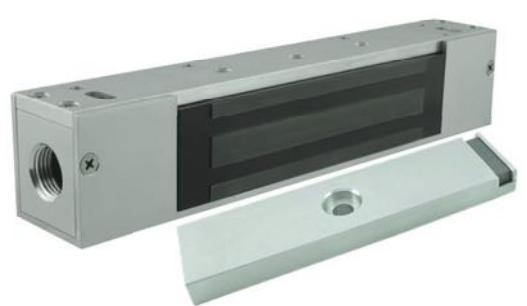
Overall Size: 10.50" L x 2.00" H x 1.75" D
IMPORTANT! THIS INSTRUCTION DETAILS THE INSTALLATION OF THE MAGNETIC LOCK ASSEMBLY ON THE PUSH SIDE OF THE DOOR. READ THOROUGHLY BEFORE ATTEMPTING INSTALLATION. DO NOT DAMAGE OR MARK MAGNETIC LOCK OR ARMATURE FACE-MAY REDUCE HOLDING EFFICIENCY.
Electrical Instructions:
NOTE: THIS PRODUCT IS INTENDED TO BE USED IN CLASS 1, DIVISION 2 HAZARDOUS LOCATIONS. THE FOLLOWING GUIDELINES MUST BE OBSERVED TO REDUCE THE RISK OF FIRE EXPLOSION.
All national and local codes must be followed in the installation of the magnetic lock assembly. For code interpretation, consult a local code authority.
This unit must be connected to a NEC (National Electric Code, NFPA 70) Class 2 Supply Circuit rated for 24 VDC with a minimum current output of 0.5 amperes and output power of 12 watts. A UL Listed SDC 600 Series Power Controller is recommended.
Operating temperature for the magnetic lock will not exceed 185° F (85° C). Maximum ambient temperature is not to exceed 104° F (40° C). For supply connections, use a suitable wire with a minimum insulation temperature rating of 167° F (75° C).
To reduce the risk of the ignition of hazardous atmosphere, disconnect the magnetic lock assembly from the supply circuit before opening the magnetic lock housing. Keep the unit properly sealed while in operation. To reduce the risk of fire or explosion, do not install the unit where the operating temperature exceeds the ignition temperature of the hazardous atmosphere.
This unit is intended to be used in the following atmospheres: Acetone, Ammonium Hydroxide, ATSM fuel C, Benzene, Methyl-Ethylketone, Diethyl-Ether, 2-Nitropropane, Ethyl-Acetate, Furfural, Normal Hexane, Methyl Alcohol
Electrical Specifications:
Input Voltage: 24VDC +/- 10%
Power Consumption: 250mA @ 24VDC
Holding Force: 600 lbs.
Door Status Sensor: SPDT Output,
100mA @ 30VDC Max.
Wiring:
Lock Wiring: RED/RED (Non-Polarized)
DPS Wiring: White (N.O.)
Red (N.C)
Black (Common)
(Door in the OPEN position)

Any suggestions or comments to this instruction or product are welcome. Please contact us through our website or email engineer@sdcsecurity.com
See Figure 1 elevation profiles to determine mounting application requirements for each individual application. NOTE: A 2-1/2" (64 mm) reveal is required to assure rigid mounting of the EP17624.
Figure 1 - Magnetic Lock Mounting To Frame
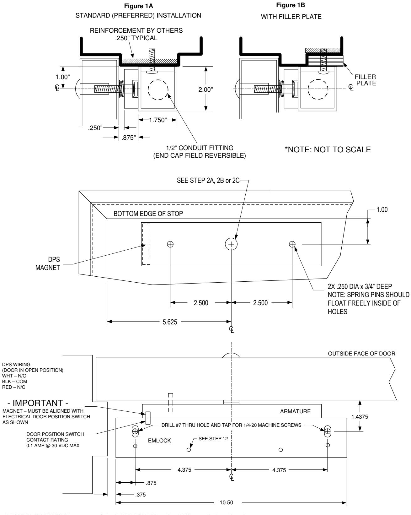
- STEP 1. Mark door(s) according to armature location template and dimensions on Page 2.
- STEP 2. Drill and prep holes in door per armature template on Page 2 and door type below:
2A. For THRU BOLT mounting in hollow metal door(s) drill 11/32" (9 mm) DIA. hole thru door, enlarge hole in outside face to 1/2" (13 mm) DIA.
2B. For THRU BOLT mounting in solid core wood door(s), drill 11/32" (9 mm) DIA. hole thru door(s), enlarge hole in outside face to 1/2" (13 mm) DIA., 1" (25 mm) deep.
2C. For REINFORCED DOOR (Minimum 3/8" (10 mm) thickness) drill and tap thru reinforcement for 5/16"-18 screw.
- STEP 3. Gently tap the (2) 3/16" (5 mm) diameter spring pins into rear side of armature(s).
- STEP 4. Insert one (1) spring washer over 5/16"-18 "special" shoulder bolt, insert bolt through armature. Add three (3) conical spring washers and one (1) flat washer over shoulder bolt. See Figure 2 - details for each type of installation. All parts must be assembled properly before installing armature to the door. Install the complete armature assembly on the door per Figure 2 details.
2AA SHOULDER BOLT SEX NUT SPRING WASHERS (4X) ARMATURE FLAT WASHER HOLLOW METAL DOOR WOOD DOOR REINFORCED DOOR Figure 2A Figure 2B Figure 2C CL CL CL
Figure 2 – Armature Mounting To Door(s)
STEP 5. Tighten shoulder screw(s) securely with allen wrench. (Do not overtighten.)
NOTE: ALL ARMATURES ARE NORMALLY EQUIPPED WITH A PERMANENT MAGNET ON ONE END. BE CERTAIN TO INSTALL ARMATURE SO DPS MAGNET LINES UP WITH THE DOOR POSITION SWITCH INSIDE THE HOUSING OF MAGNETIC LOCK ASSEMBLY.
- STEP 6. Remove housing cover of maglock assembly by removing the two (2) phillips screws on the front face of the maglock, and the (2) phillips screws on the back of the housing.
- STEP 7. Mark frame per EMLock template and dimensions on Page 2.
- STEP 8. Drill two (2) #7 thru holes and tap for 1/4-20 machine screws per the EMLock template. Attach maglock assembly to the frame using either (2) #14 sheet metal screws OR (2) 1/4"-20 machine screws and external tooth lock washers, tighten only enough to hold the unit in place. (If filler plate is used, assure that the screws go through both the filler plate and the door frame.)
- STEP 9. Run electrical conduit per NFPA 70 into conduit hole with 1/2-14 NPT.
- STEP 10. Make all electrical connections per applicable wiring instructions. Use wire nuts, crimp connectors or solder to assure good connections.
- STEP 11. Energize EMLock assembly. Adjust assembly so door is snug against door stop; Tighten two (2) preliminary screws in Step 8 securely.
- STEP 12. De-energize system. Using mounting plate as template, drill #21 drill and tap for 10-32 screws (minimum two (2) places). Install screws and tighten securely. Re-energize system, recheck alignment of EMLock assembly to armature by opening and closing door(s).
- STEP 13. Re-install EMLock housing cover.

ISSUE # U-557
DOOR HOLDER FOR USE IN HAZARDOUS LOCATIONS Class 1 Div 2
24 VOLTS D.C. 0.25 AMP 6.0 WATTS OPERATING TEMPERATURE 85 DEGREE CENTIGRADE MAXIMUM AMBIENT TEMPERATURE 40 DEGREE CENTIGRADE FOR SUPPLY CONNECTIONS USE 75 DEGREE CENTIGRADE WIRE THIS UNIT MAY BE USED IN THE FOLLOWING ATMOSPHERE: ACETON, AMMONIUM HYDROXIDE, ASTM FUEL C, BENZENE, METHLY ETHYL KETONE, DIETHYL EHTER, 2-NITRO-PROPANE, ETHYL ACETATET, FURFURAL, NORMAL HEZANE, METHYL ALCOHOL
CAUTION:
TO REDUCE THE RISK OF IGNITION OF HAZARDOUS ATMOSPHERES, DISCONNECT THE DOOR HOLDER FROM THE SUPPLY CIRCUIT BEFORE OPENING. KEEP TIGHTLY CLOSED WHEN IN OPERATION. TO REDUCE THE RISK OF FIRE OR EXPLOSION, DO NOT INSTALL WHERE THE MARKED OPERATION TEMPERASTURE EXCEEDS IGNITINO TEMPERATURE OF HAZARDOUS ATMOSPHERES.