EM Locks Installation Instructions
Open the original PDF document
View PDF[t] 800.413.8783 ■ 805.494.0622 ■ E-mail: service@sdcsecurity.com ■ 801 Avenida Acaso, Camarillo, CA 93012 ■ PO Box 3670, Camarillo, CA 93011
INSTALLATION INSTRUCTIONS
1510, 1570, 1580 SERIES EMLOCK®
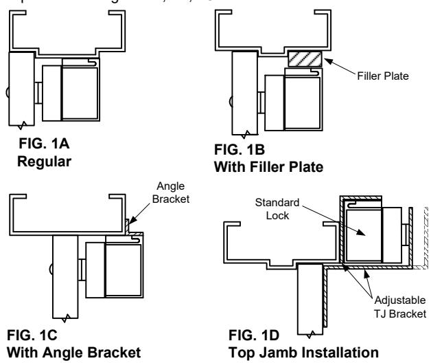
The 1500 Series Emlock is mounted to the underside of the header, on the stop side of the door. A TJ mounting kit (optional) can be used when mounting on the hinge side of the door. (Fig. 1D)
The armature is mounted to the door. A hardware kit is provided to compensate for misalignment and wear of the door, by allowing the armature to pivot on it's center point.
Inspect the frame header to determine if an angle bracket or filler plate is required. See Figure 1A, 1B, 1C.
- Fold template as indicated by dotted line. For single doors, locate template against the door and header on the lock jamb side of the frame.
- 3. Mark and drill holes as indicated bt template. For armature plate hole preparation, see Figure 2A, 2B, 2C.
- Mount armature to door. To determine proper hardware (provided), see Figure 2A, 2B, 2C.
- Install mounting plate to header with the interlock detail away from the door side of the stop, with #10 Flt Hd. Screws provided.
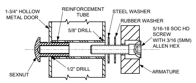
FIG. 2A HOLLOW METAL DOOR
From Sexnut side of door, drill exactly 1/2" hole thru one metal thickness only. From Armature side of door, drill 5/8" hole to insert reinforcement tube. Press in sexnut and reinforcement tube all the way and mount armature to door using hardware provided per Figure 2B.
Holding the magnet housing at each end, engage the entire length of the interlock detail, by pushing towards the door. (If necessary, tap with a soft hammer to ensure proper alignment and engagement).
Caution: The lock body must be held in place until secured with mounting screws. Screws provided inside the housing at each end. Tighten the screws and check alignment.
Test operation. When all is operating properly, tighten all screws. Install anti-tamper plugs over socket head screw using a soft hammer to avoid damage to the housing.
Electromagnet and armature should be handled carefully. Any damage to the surface such as paint, burrs, dirt and rust may hinder bonding of surface and reduce holding power.
SHOULD THE SURFACE PLATING BE DAMAGED:
Do not touch the lock face with your hands.
Using a soft, clean, dry cloth or abrasive cloth (i.e., Scotch-Brite), clean lock face. Do not use sand paper.
A rust inhibitor such as M1, manufactured by Starret, or LPS3, manufactured by LPS Laboratories (available at most hardware stores) can then be applied.
Apply a coat of inhibitor to armature face also.
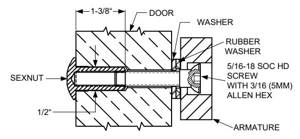
FIG. 2B SOLID DOOR
Drill 3/8" hole thru door. From sexnut side of door, drill exactly 1/2" hole, 1-3/8" deep. Mount armature to door with hardware provided per Figure 2A.
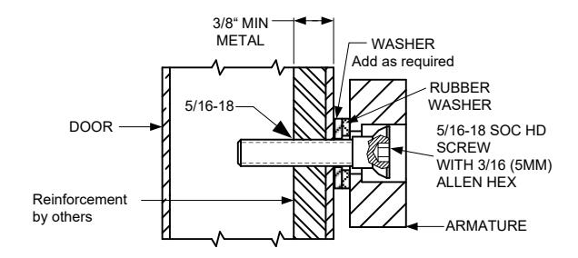
FIG. 2C REINFORCED DOOR Drill and tap for 5/16-18 machine screw. Mount armature to door with hardware provided per Figure 2C.
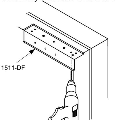
OPTIONAL: 1511-DF DRILL FIXTURE
Drill many doors and frames in a fraction of the time.
ELECTRICAL SPECIFICATIONS
Voltage kickback protection standard
| SERIES | 1510 | 1570 | 1580 |
|---|---|---|---|
| INPUT VOLTAGE (VDC) | 12/24 | 12/24 | 12/24 |
| POWER CONSUMPTION (mA) | 700/350 | 250/125 | 440/220 |
| COIL RESISTANCE (OHMS) | 35* (PER COIL) | 100* (PER COIL) | 60* (PER COIL) |
| HOLDING FORCE (LBS) | 1650 | 1200 | 650 |
*NOTE: For a proper coil resistance reading, turn off the DC voltage. Use an ohmmeter and measure the resistance between the pins of the plug connector positions E1-E2 and E3-E4
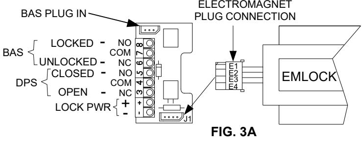
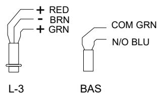
1510, 1570 SERIES CONNECTIONS ELECTROMAGNET
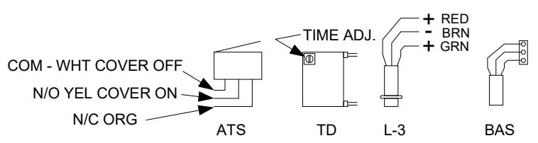
AVAILABLE OPTIONS
ATS Anti-Tamper Switch SPDT, DRY, BAS SPDT. DRY. Magnetic Bond Sensor DPS Door Position Switch SPDT, DRY, LED Tri-Color LED Red or Green 20 mA Both on = Yellow 40 mA TD TIME DELAY (1-30 sec) 20 mA
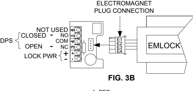
1580 SERIES CONNECTIONS
AVAILABLE OPTIONS
| BAS | Magnetic Bond Sensor | SPST, No, Dry |
|---|---|---|
| DPS | Door Position Switch | SPDT, Dry |
| LED | Tri-Color LED Red or Green | 20 mA |
| Both on = Yellow | 40 mA | |
All switches rated @ 250 mA @ 30 VDC
ELECTRICAL INSTALLATION
- Use jacketed cable for all wire runs. Refer to the SDC wire gauge chart for proper lock power wire size (18 AWG gauge minimum).
- 2. Use only shielded cable for all signal wires. 22 AWG gauge (minimum) may be used for signal wires up to 1,000 feet.
- 3. All wires must be colored coded.
- Use properly fused power source only. See Electrical Specifications.
- Make all Emlock terminal connections according to Figure 3A or 3B.
IMPORTANT NOTES
INDOOR USE ONLY
Do not run power wires and signal wires in the same cable or conduit.
<u>Do not install a diode</u> in parallel with any magnetic lock. A diode will cause a delay when releasing the door and residual magnetism to occur.
Although SDC recommends the use of a DC power supply, a transformer with an adjacent mounted full wave bridge rectifier may be used. A significant voltage drop will occur when using a full wave bridge rectifier.
Any low voltage condition will cause erratic operation of the optional bond sensor.
When using a full wave bridge rectifier, all access controls and/or release contacts must be located between the Emlock and rectifier to ensure quick release.
AWG WIRE CHART
To determine the correct wire gauge to use on "one circuit" the following information is required:
- 1. The quantity, voltage, and current draw of all lock(s) to be used.
- 2. The distance in feet from the power supply to the furthest lock.
Add together the current draw (amps) of all locks on the same circuit. Cross reference the total amps with the distance between the power source and the furthest lock to determine the wire gauge required. All wiring must be installed in accordance with all state and local codes.
| DISTANCE IN FEET FROM POWER SOURCE TO FARTHEST LOCKING DEVICE | ||||||||||||
|---|---|---|---|---|---|---|---|---|---|---|---|---|
|
Minimum
Wire Gauge for 12 Volts AC or DC |
AMPS 0.25 0.50 0.75 1.00 1.50 2.00 2.50 |
25
18 18 18 18 18 18 16 |
50
18 18 18 16 14 14 |
75 18 18 16 14 12 12 |
100
18 16 14 14 12 |
150 18 16 12 12 |
200
16 14 12 |
250 16 12 |
300
14 |
400
14 |
500
12 |
1000 |
| DISTANCE IN FEET FROM POWER SOURCE TO FARTHEST LOCKING DEVICE | ||||||||||||
|
Minimum
Wire Gauge for 24 Volts AC or DC |
AMPS 0.25 0.50 0.75 1.00 1.50 2.00 2.50 | 25 18 18 18 18 18 18 18 |
50
18 18 18 18 18 18 16 |
75 18 18 18 18 16 16 14 |
100
18 18 18 16 14 14 12 |
150
18 18 16 14 14 12 |
200
18 16 14 14 12 |
250
18 16 14 12 |
300
18 14 12 12 |
400
16 14 12 |
500
16 12 |
1000
16 |
| TROU | BLE SHO | OTING | . | |||||||||
|
PROBLEM
Emlock relea |
CAUSE Control switch wired on AC side of power source. | SOLUTION Control switch must be wired on DC side of power supply. | ||||||||||
| (residual magnetism) | When an AC transformer and rectifier are used, the control switch must be wired between the rectifier and the Emlock. | |||||||||||
| Field | installed d | iode in pa | rallel with p | oower inpu | ıt. | Remov | e diode. | |||||
| Poor holding | force. | Arma | ture install | ed rigidly. | Armature must pivot loosely from its center mounting point to permit full armature contact. | |||||||
| Check for proper voltage at the Emlock input. If low, determine if the correct wire gauge is being used to prevent excessive voltage drop. | ||||||||||||
| Low | oltage. | Check power supply load capacity. It must meet or exceed the combined current rating of all locks on the circuit. | ||||||||||
|
AC vo
(Emlo |
oltage inpu
ock will ma |
ıt.
ke a humr |
ming noise | ) | Emlocks require DC input voltage. When AC voltage from a transformer is used, a full wave bridge rectifier must be installed to convert the AC voltage to DC voltage. | |||||||
| No holding for Door does n | No po | ower. | e voltage is low or zero, the power supply. | |||||||||
| Input | polarity re | versed. | Check voltage polarity. Terminal (-) is: Negative. Terminal (+) is: Positive. | |||||||||
| Open circuit in Emlock coil. | Check coil continuity with OHM meter. If reading is high or open, replace the magnet coil. See Fig. 3A and the Resistance Specifications. | |||||||||||
Coil shorts or incorrect wiring will blow fuses. Measure the coil
for correct resistance. See Fig. 3A and the Resistance
specifications.
Magnet coil short.
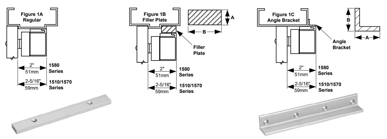
FILLER PLATES: For extension of the stop to provide a proper mounting surface on the underside of the header. See Figure 1B.
FOR 1581 SINGLE EMLOCK MODELS
| PART# | SIZE | Α | В |
• |
|
|---|---|---|---|---|---|
| FP01 | 1/8" x | 1-1/4" | (3 x 32mm) | ||
| FP02 | 1/4" x | 1-1/4" | (6 x 32mm) | 8-3/4" | |
| FP03 | 3/8" x | 1-1/4" | (10 x 32mm) | (222mm) | |
| FP04 | 1/2" x | 1-1/4" | (13 x 32mm) | (22211111) | |
| FP05 | 5/8" x | 1-1/4" | (16 x 32mm) |
FOR 1511, 1571 SINGLE EMLOCK MODELS
| PART# | SIZE | Α | В | _ | • | |
|---|---|---|---|---|---|---|
| FP11 | 1/8" x | 1-1/4" | (3 x 32mm) | |||
| FP12 | 1/4" x | 1-1/4" | (6 x 32mm) | 11" | ||
| FP13 | 3/8" x | 1-1/4" | (10 x 32mm) | (279mm) | ||
| FP14 | 1/2" x | 1-1/4" | (13 x 32mm) | (27311111) | ||
| FP15 | 5/8" x | 1-1/4" | (16 x 32mm) |
FOR 1582 DOUBLE EMLOCK MODEL
| PART# | SIZE | Α | В | ||
|---|---|---|---|---|---|
| FP30 | 1/8" x | 1-1/4" | (3 x 32mm) | ||
| FP31 | 1/4" x | 1-1/4" | (6 x 32mm) | 17-1/2" | |
| FP32 | 3/8" x | 1-1/4" | (10 x 32mm) | (445mm) | |
| FP33 | 1/2" x | 1-1/4" | (13 x 32mm) | (44311111) | |
| FP34 | 5/8" x | 1-1/4" | (16 x 32mm) |
FOR 1512, 1572 DOUBLE EMLOCK MODELS
| PART# | SIZE | Α | В | • | |
|---|---|---|---|---|---|
| FP21 | 1/8" x | 1-1/4" | (3 x 32mm) | ||
| FP22 | 1/4" x | 1-1/4" | (6 x 32mm) | 22" | |
| FP23 | 3/8" x | 1-1/4" | (10 x 32mm) | (559mm) | |
| FP24 | 1/2" x | 1-1/4" | (13 x 32mm) | (33311111) | |
| FP25 | 5/8" x | 1-1/4" | (16 x 32mm) |
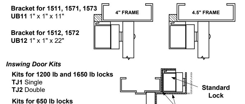
Multiple predrilled and tapped mounting holes to accommodate the use of several different locks on either 4" or 4.5" aluminum frames.
ANGLE BRACKETS: Used as extension on shallow door frames to provide adequate mounting surface. See Figure 1C.
FOR 1581 SINGLE EMLOCK MODELS
| PART # | SIZE | Α | В | _ | |
|---|---|---|---|---|---|
| AB01 | 1" | x 1" | (25 x 25mm) | ||
| AB02 | 1" | x 1-1/2' | ' (25 x 38mm) | 8-3/4" | |
| AB03 | 1-1/2" | x 1-1/2 | " (38 x 38mm) | (222mm) | |
| AB04 | 2" | x 1-1/2' | ' (51 x 38mm) |
FOR 1511, 1571 SINGLE EMLOCK MODELS
| , - | ||||
|---|---|---|---|---|
| PART# | SIZE | Α | _ | |
| AB11 | 1" | x 1" (25 x 25mm) | ||
| AB12 | 1" | x 1-1/2" (25 x 38mm) | 11" | |
| AB13 | 1-1/2" | x 1-1/2" (38 x 38mm) | (279mm) | |
| AB14 | 2" | x 1-1/2" (51 x 38mm) |
FOR 1582 DOUBLE EMLOCK MODEL
| PART# | SIZE | Α | В | |
|---|---|---|---|---|
| AB31 | 1" | x 1" (25 x 25mm) | ||
| AB32 | x 1-1/2" (25 x 38mm) | 17-1/2" | ||
| AB33 | x 1-1/2" (38 x 38mm) | (445mm) | ||
| AB34 | x 1-1/2" (51 x 38mm) | | ` ' ' |
FOR 1512, 1572 DOUBLE EMLOCK MODELS
| PART# | SIZE | Α | В | ||||
|---|---|---|---|---|---|---|---|
| AB21 | 1" | Х | 1" | (25 x 25mm | า) | ||
| AB22 | 1" | Х | 1-1/2" | (25 x 38mn | n) | 22" | |
| AB23 | 1-1/2" | Х | 1-1/2" | (38 x 38mn | n) | (559mm) | |
| AB24 | 2" | Х | 1-1/2" | (51 x 38mn | n) |
• Field adjustable for 1/2", 5/8" and 3/4" all glass Herculite doors.
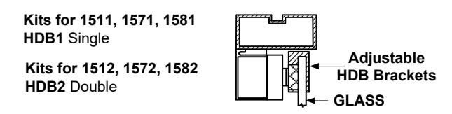
Adjustable
TJ Bracket
TJ81 Single
TJ82 Double