EL980 Electric Lockable Non-Fire Rated Mullion Installation Instructions
Open the original PDF document
View PDF

EL980 Electric Lockable
Non Fire-Rated Mullion
Tools Required: Measuring Tape, Pencil, Drill & Tap Sizes #7 drill and 1/4"-20 tap, Concrete Drill 3/8" diameter, Center Punch, Hammer, #3 Phillips Screwdriver, 5/64" Allen Wrench, 1/8" Allen Wrench
To install mullion in frame:
- 1. Close and block the doors against the frame stops. Check gap betweendoor leaves and door to frame and correct if necessary.
-
2. Locate the center of the opening on the floor. Using the bottom retainer, mark the positions for the two drop-in fasteners.
- a. The bottom of the door should come to rest against the surface of the mullion.
- b. Modify threshold as required.
- 3. Drill holes with 3/8" diameter cement bit to a minimum depth of 2-1/2".
- 4. Fasten bottom bracket to floor.
-
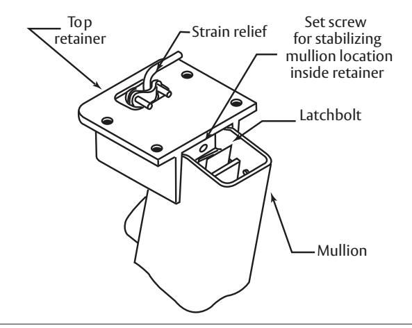
5. Locate the center of the opening on the top of the frame. Using the top retainer, mark the positions for the four fasteners.
- a. The door should evenly rest against both the frame stop and the mullion.
- b. If a top retainer mounting kit is used, modify weather stripping as required.
- 6. Drill and tap each location for 1/4"-20 fasteners.
- 7. Mount top retainer on frame with fasteners provided.
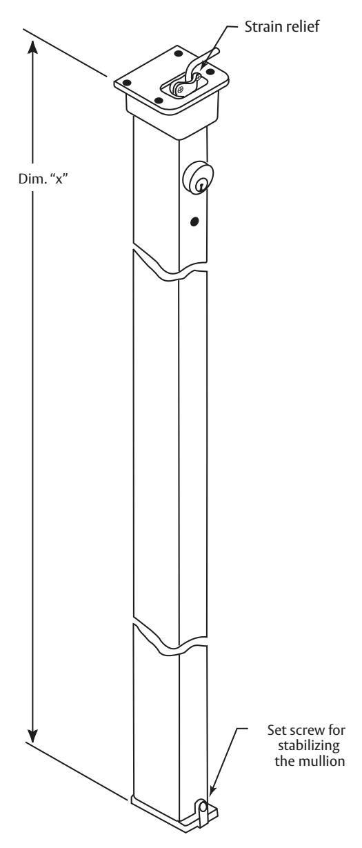
- 8. Measure "Dim X" as shown. Remove material from the bottom of the mullion per the formula: length of mullion = "Dim X" 3/4".
Note: This leaves approximately 1/8" clearance between the mullion and the top bracket when mounted.
- 9. Place mullion onto bottom bracket and pivot into opening to latch.
- 10. Tighten bottom bracket set screw to prevent mullion rattle. Do not over tighten (1/8" allen wrench).
- 11. Install exit devices according to manufacturer's instructions.

to www.P65warnings.ca.gov.
Assembly Instructions for EL980 Mullion

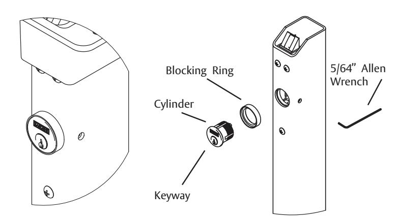
Installation of cylinder:
- 1. Depress latchbolt and hold fully retracted.
- 2. Carefully thread cylinder with blocking ring into lock assembly until it bottoms out.
- 3. Unscrew the cylinder orienting keyway at bottom.
- 4. Release latch bolt. Note: If latch bolt is not fully projected loosen cylinder an additional 1-2 full turns.
- 5. Tighten set screw with 5/64" Allen Wrench through access hole in side of mullion.
- 6. Check operation of cylinder and lock assembly. Note: Key only turns counter-clockwise.

Install standard strain relief (not supplied). Insert wire so wire connector is 2" from base of top retainer and tighten securely.

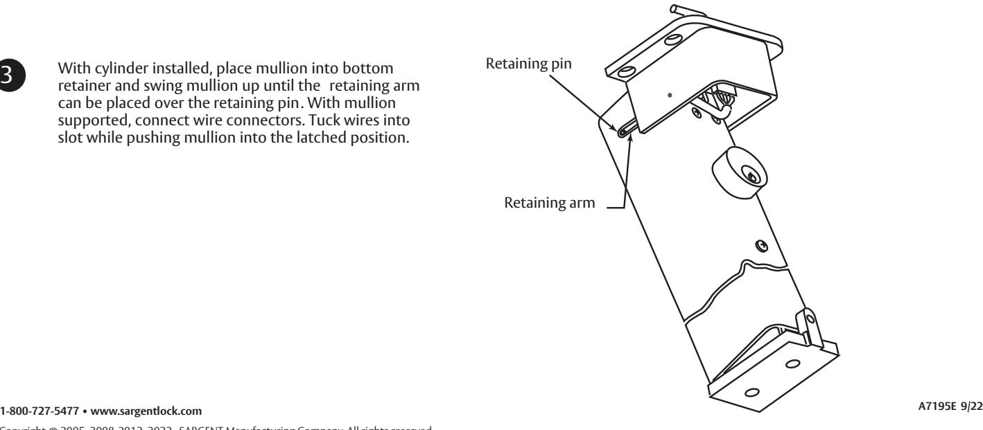
With cylinder installed, place mullion into bottom retainer and swing mullion up until the retaining arm can be placed over the retaining pin. With mullion supported, connect wire connectors. Tuck wires into slot while pushing mullion into the latched position.