ED EF1400 Installation
Open the original PDF document
View PDFED1400/1400F SERIES MORTISE LOCK EXIT DEVICE
INSTALLATION INSTRUCTIONS
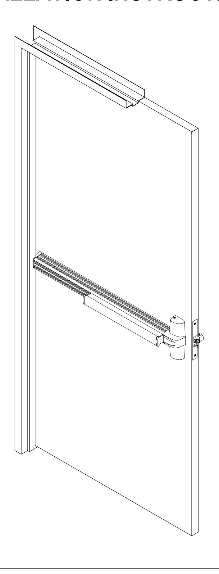
1400 SERIES MORTISE EXIT DEVICE
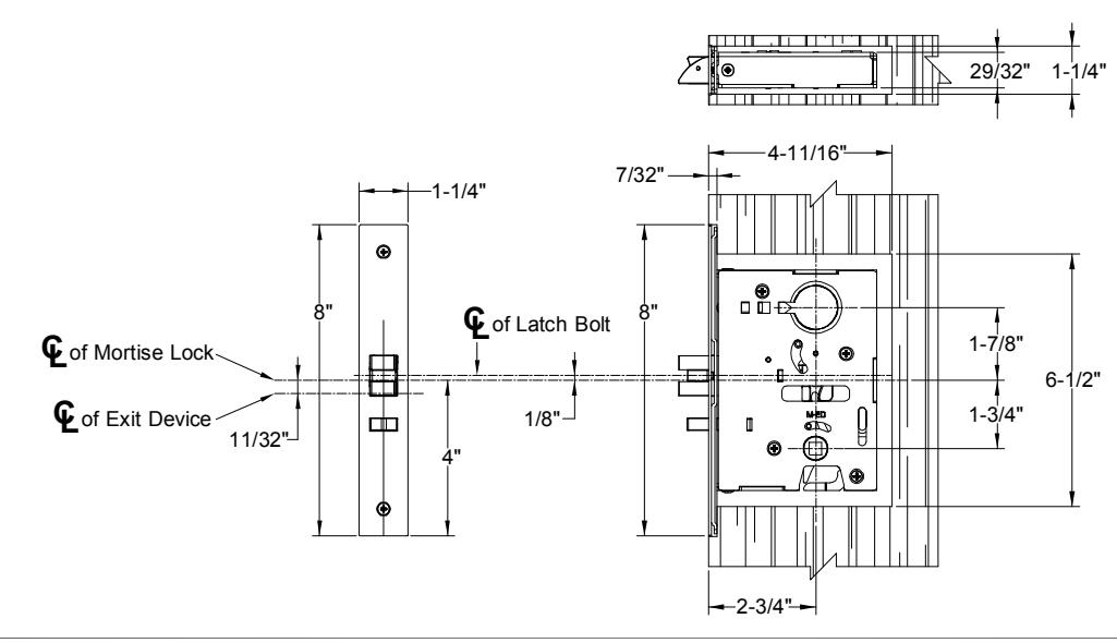
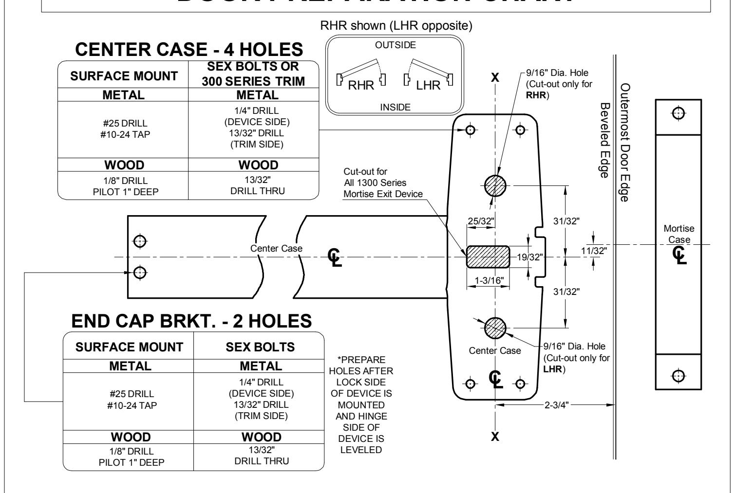
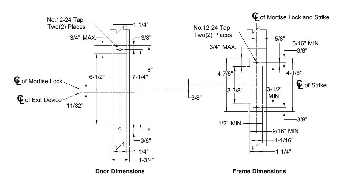
DOOR PREPARATION CHART
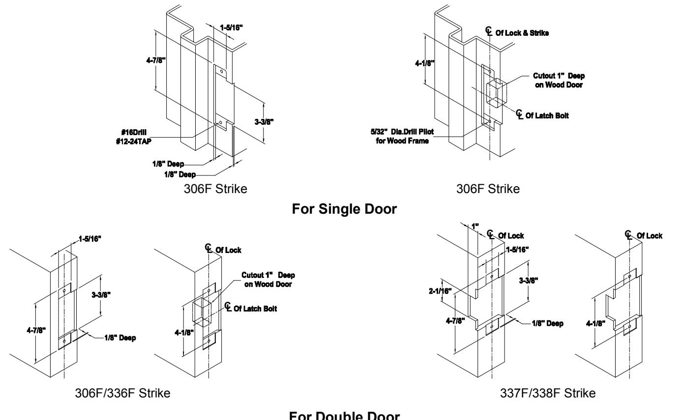
STRIKE PREPARATION
1 DRAW HORIZONTAL DEVICE CENTERLINE (©).
RHR shown (LHR opposite) Hinge Side 39-5/8" to Finished Floor or Threshold
Close door, mark horizontal centerline on inside face of door and on lock side door stop 39-5/8" from finish floor as shown, (Continue horizontal centerline to outside face of door if trim is using)
2 ALIGN TEMPLATE ALONG CENTERLINE (©) AND MARK DOOR.
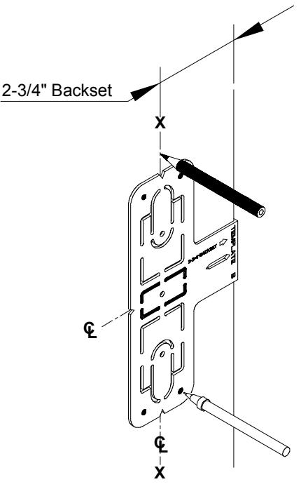
Mark four(4) center case holes. Mark vertical centerline at lock side using 2-3/4" backset dimension.
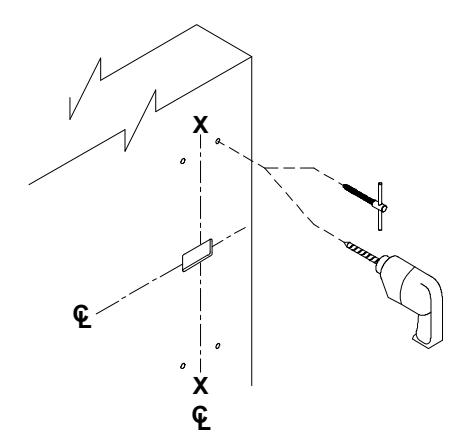
3 PREPARE FOUR(4) CENTER CASE HOLES AND MORTISE LOCK CUTOUTS.
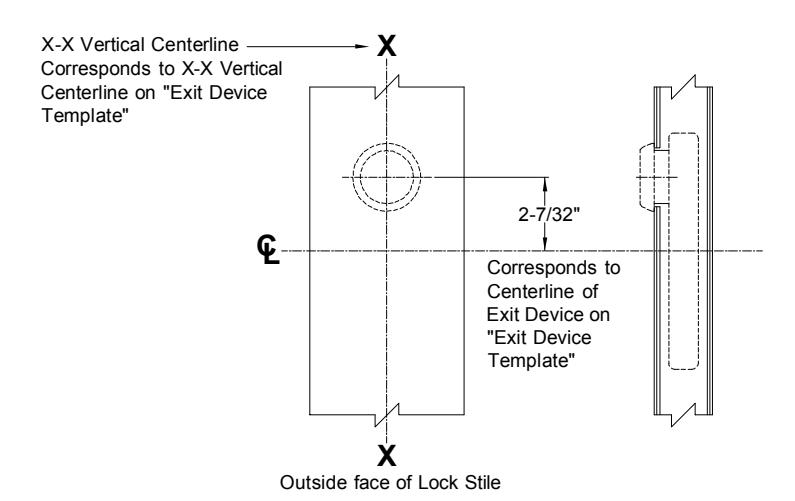
- 3A. Mark vertical centerline at lock side using 2-3/4" backset dimension (If trim is using mark vertical centerline on the outside face of door. Use extra care if edge of door is beveled, be sure X-X vertical centerline is parallel to edge of door).
- 3B. If door is not pre-machined for mortise lock, mortise the door according to "Mortise Lock Instructions".
See "Trim Instructions" for pull side door preparation.
5 INSTALL TRIM (IF USING) AND SECURE DEVICE CENTER CASE TO DOOR.
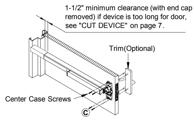
- 1. DEVICE WITH TRIM See "Trim Instructions".
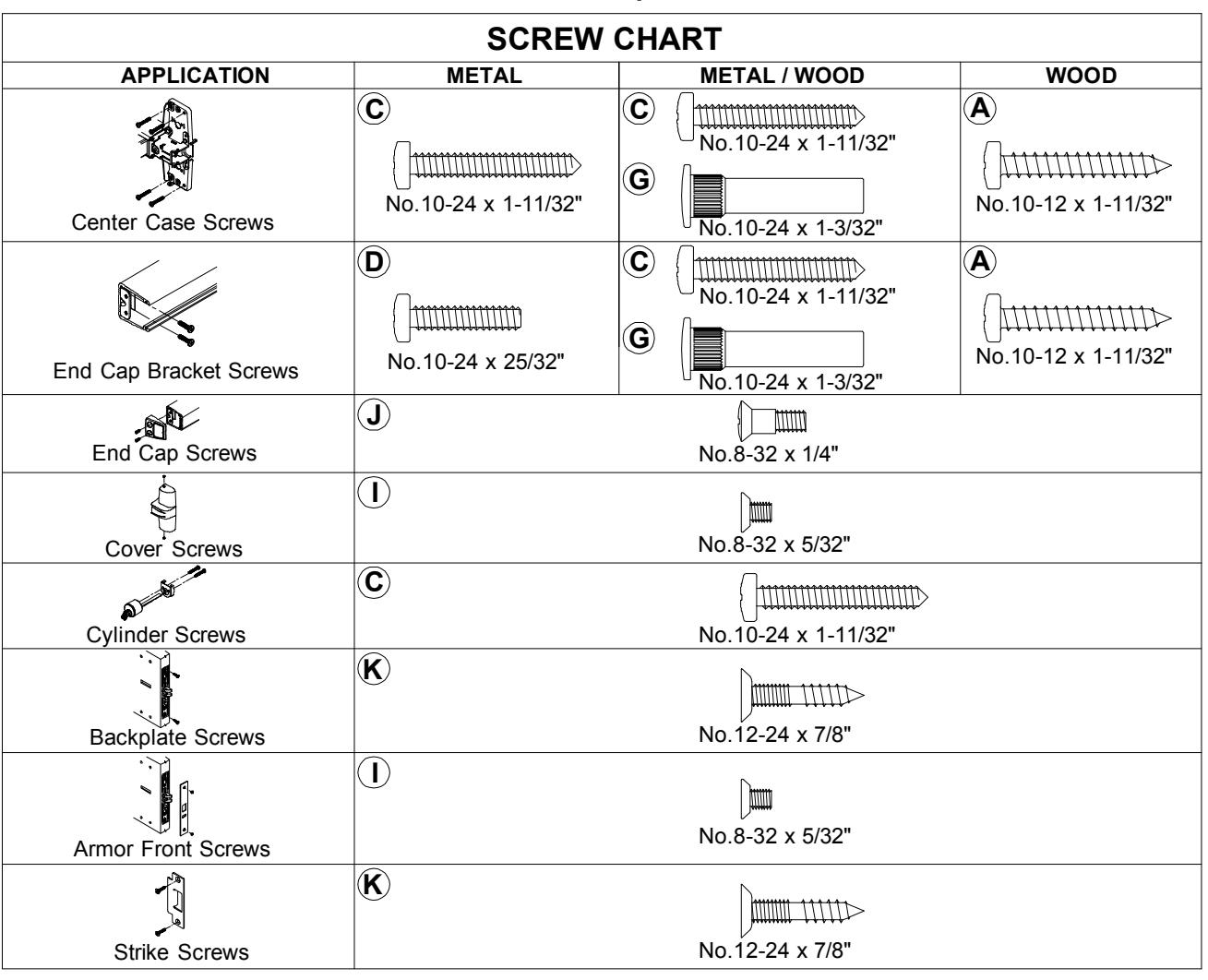
- 2. EXIT ONLY With device adjustment finger in the mortise case, mount center case to the door with four(4) screws.
For FIRE EXIT DEVICES
Sex bolts and support screws are required for composite (wood, plastic and steel covered), wood core, sheet metal and hollow metal doors without reinforcement unless door manufacturer has an alternate mounting method. Fire doors with steel reinforcement, mount devices with machine screws
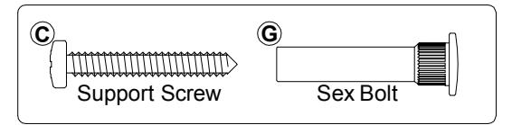
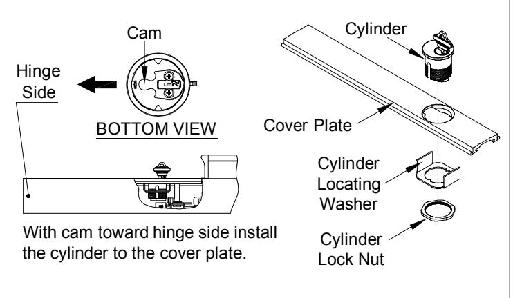
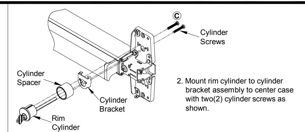
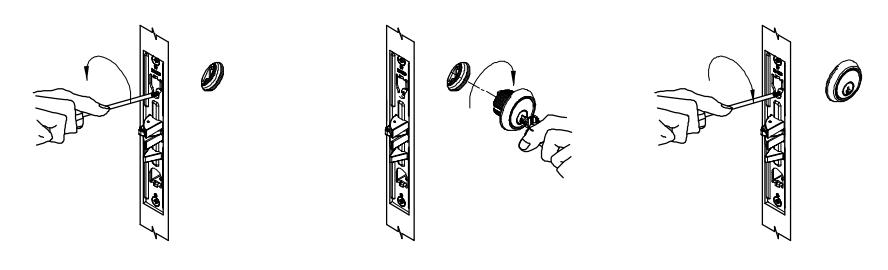
6 INSTALL OUTSIDE LOCKING CYLINDER (IF USING) AND FINISH INSTALLING MORTISE LOCK.
CYLINDER ONLY - Install mortise cylinder into mortise lock as shown. Check key operation and secure cylinder in place by tightening cylinder anchor screw into groove on side of cylinder. NOTE: See "DOUBLE CYLINDER INSTALLATION" on page 7 for double cylinder application.
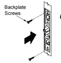
INSTALL MORTISE LOCK INTO DOOR. 4
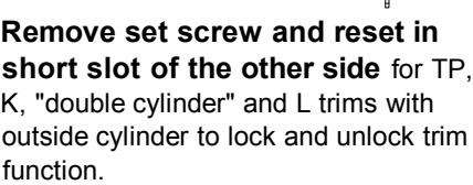
4B. Install mortise lock into door and fasten with backplate screws.
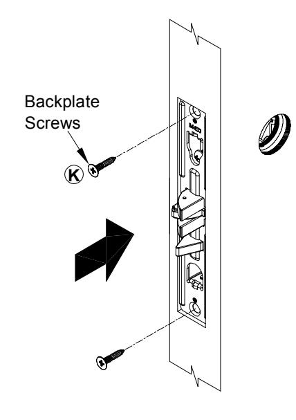
INSTALL SUPPLIED STRIKE TO FRAME OR OTHER DOOR. 7
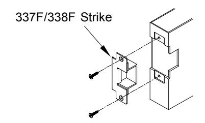
Open Back Strike For Double Door Application
See "STRIKE PREPARATION" on page 3 for preparation information.
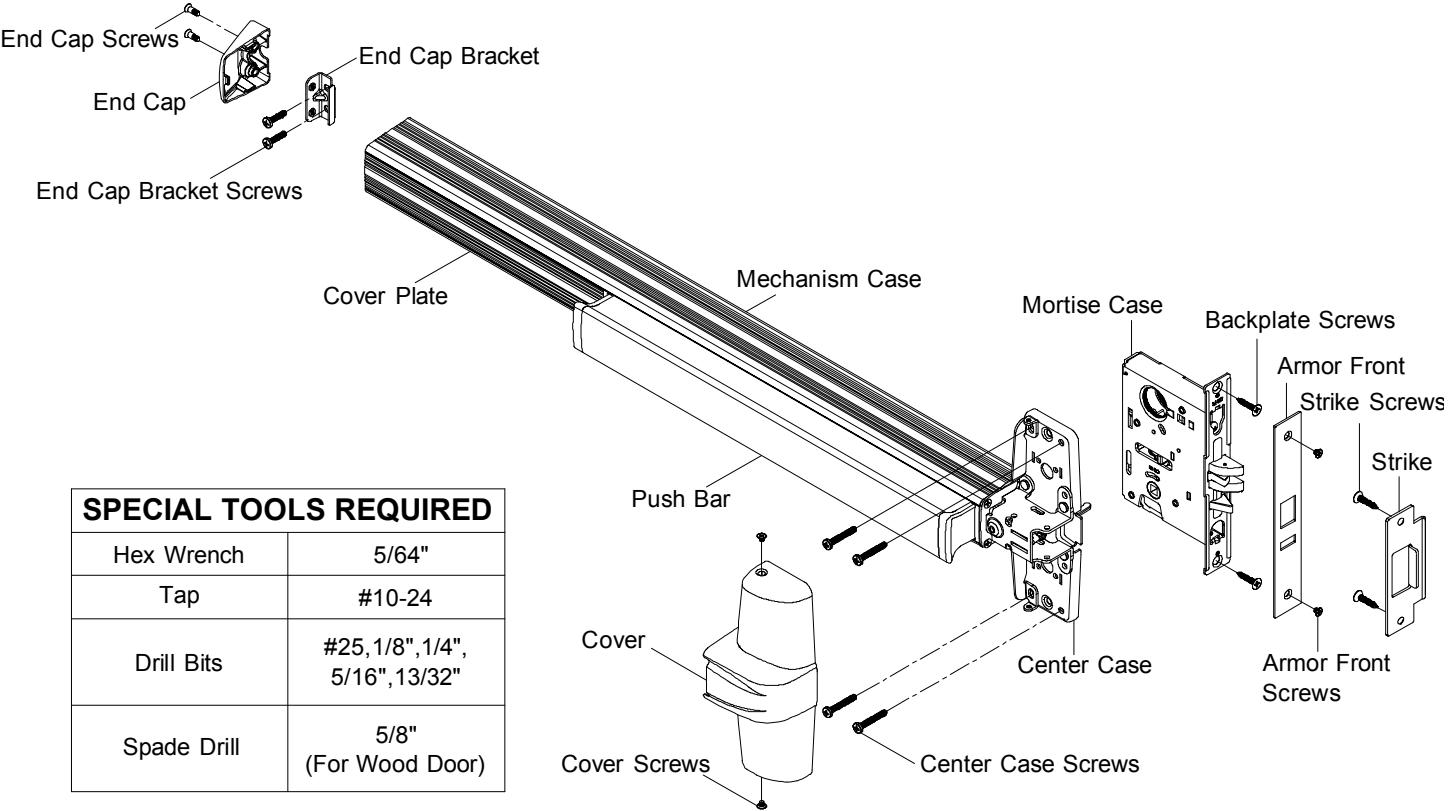
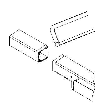
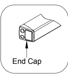
INSTALL MOUNTING BRACKET AND END CAP. 8
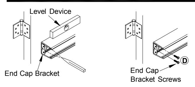
1. Remove cover plate, insert end cap bracket into push bar assembly against mechanism case. Level device, mark and drill two(2) holes for #10 sheet metal screws or #10-24 machine screws. Fasten end cap bracket screws to door.
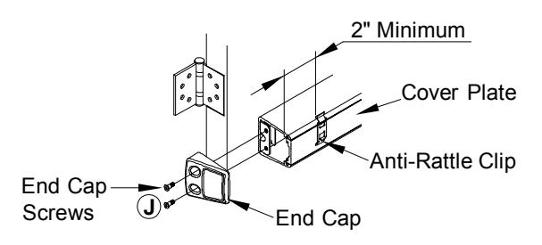
2. Insert cover plate, slide anti-rattle clip in position (2" minimum from end), and attach end cap with two(2) end cap screws.
ADJUSTING LATCH BOLT. 9
INSTALL CASE COVER. 10
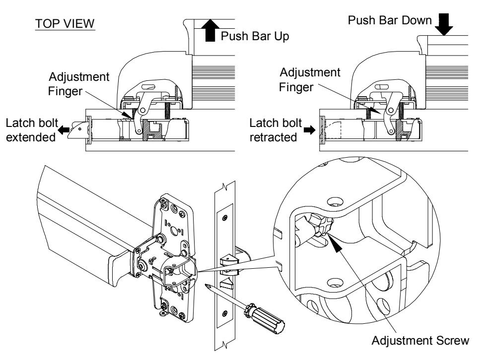
Latchbolt should be fully retracted when push bar is depressed or device is dogged down. If above condition does not exist, adjust "adjustment finger" with adjusting "adjustment screw".
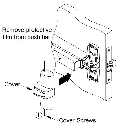
Attach cover to center case with two(2) center case screws.
OPTIONAL DOGGING
CYLINDER DOGGING
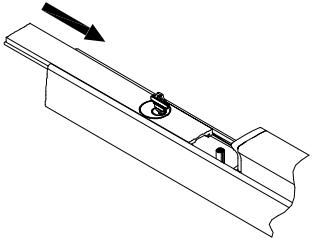
Slide cover plate in position in the mechanism case. for dogging check.
DOGGING CHECK
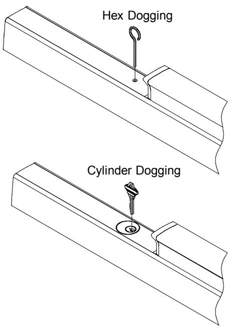
Depress push bar and turn hex wrench or key one full turn
DOUBLE CYLINDER INSTALLATION
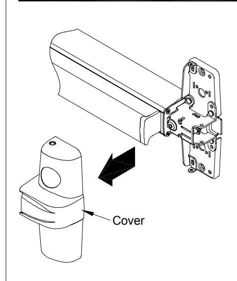
1. Remove cover.
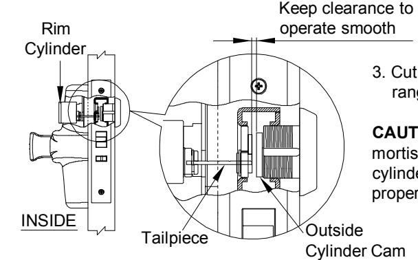
3. Cut off tailpiece for different door ranges and various cylinder lengths.
CAUTION! If the tailpiece is too far into mortise case and interferes with outside cylinder cam, both cylinders cannot be properly operated.
CUT DEVICE (IF REQUIRED)
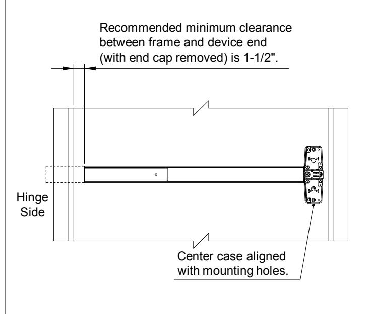
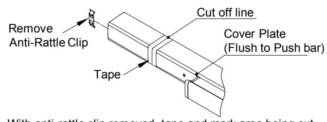
1. With anti-rattle clip removed, tape and mark area being cut.
2. Cut off device and deburr. NOTE: Device must be cut square for proper end cap fit.
ED1400/1400F SERIES MORTISE LOCK FOR EXIT DEVICE
INSTALLATION INSTRUCTIONS
- 1. Prepare door for device and trim (see their instructions).
- 2. Prepare door for mortise lock and cylinder (see preparation on other side of these instructions).
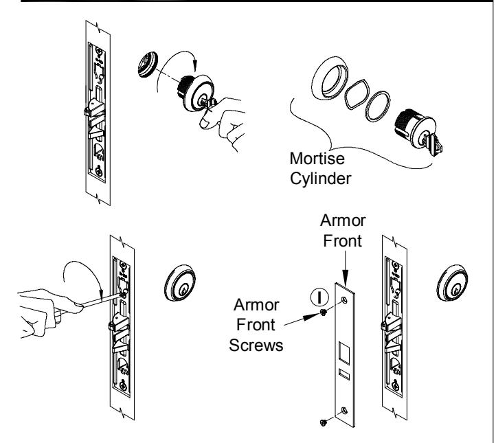
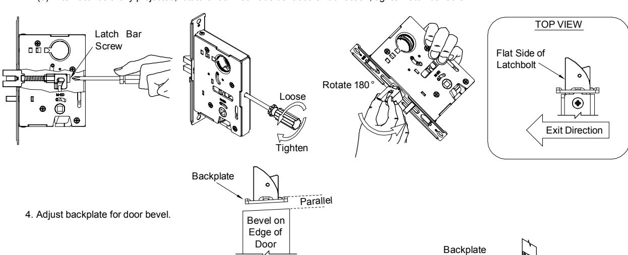
- 3. Change lock handing if required:
- (a) Loose latch bar screw to project latchbolt away from mortise case.
- (b) After latchbolt fully projected, rotate it 180 ° so flat side faces exit direction, tighten latch bar screw.
5. Install mortise case into door with two(2) No.12-24 x 7/8" backplate screws.
- 6. Install trim, if using (see "Trim Instructions").
-
7. If using outside cylinder:
- (a) Loose cylinder anchor screw sufficiently to allow cylinder to be threaded into lock case.
- (b) Screw cylinder into the lock case, keyway must end up on bottom of cylinder housing.
- (c) Secure cylinder by tightening cylinder anchor screw into groove on side of cylinder.
-
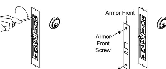
8. Finish installing mortise lock:
- (a) Tighten two(2) backplate screws.
- (b) Place armor front in position and install two(2) armor front screws.
DOOR PREPARATION FOR MORTISE CYLINDER
METAL DOOR PREPARATION FOR MORTISE LOCK
WOOD DOOR PREPARATION FOR MORTISE LOCK