ED EF1300 Installation
Open the original PDF document
View PDFED1300/1300F SERIES CONCEALED VERTICAL ROD DEVICE
INSTALLATION INSTRUCTIONS
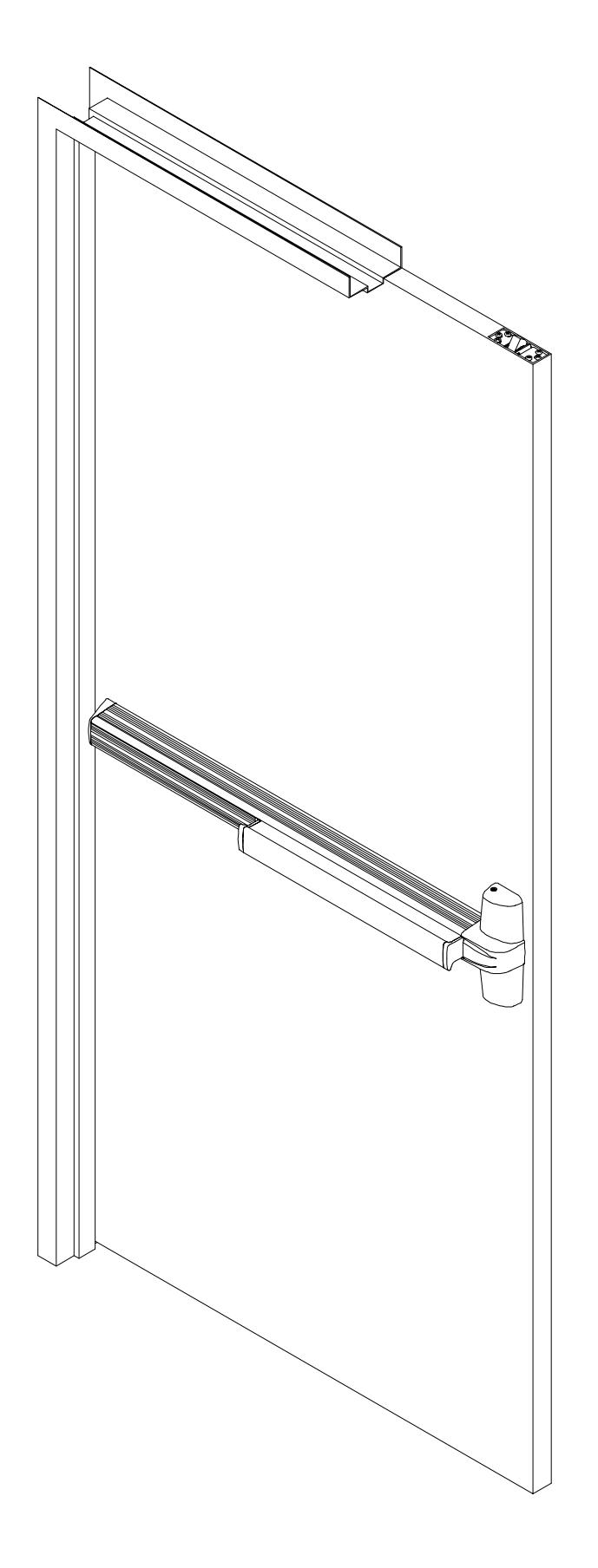
1300 SERIES CONCEALED VERTICAL ROD DEVICE
|
SPECIAL TOOLS
REQUIRED |
|
|---|---|
| Hex Wrench | 5/64" |
| Tap | #10-24 |
| Drill Bits |
#25,1/8",1/4",
5/16",13/32" |
| Spade Drill |
5/8"
(For Wood Door) |
DOOR PREPARATION CHART
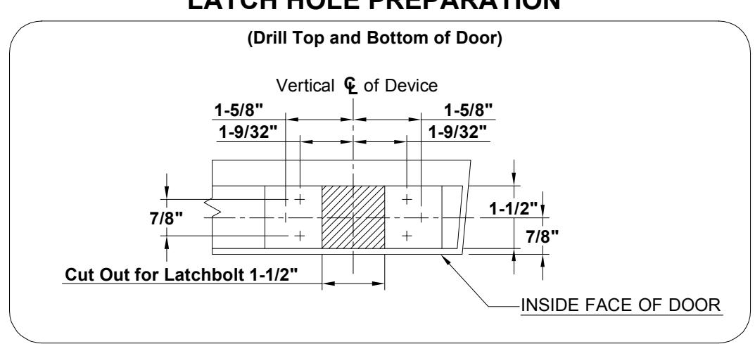
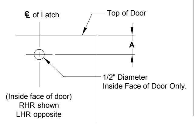
LATCH HOLE PREPARATION
1 DRAW HORIZONTAL DEVICE CENTER LINE($\mathbb{C}$).
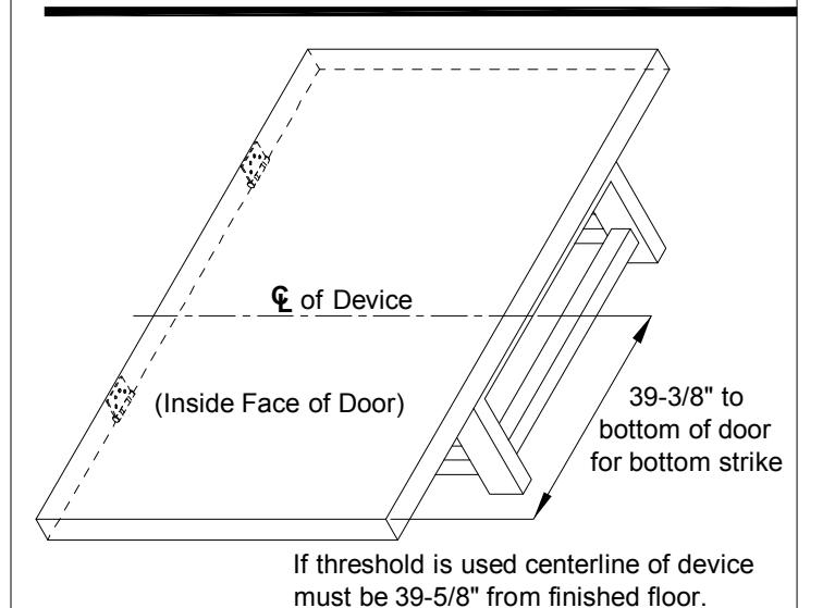
RHR shown (LHR opposite)
Lay door in place and draw horizontal device center line as shown.
(bottom door gap must be 1/4")
2 DRAW VERTICAL & MARK
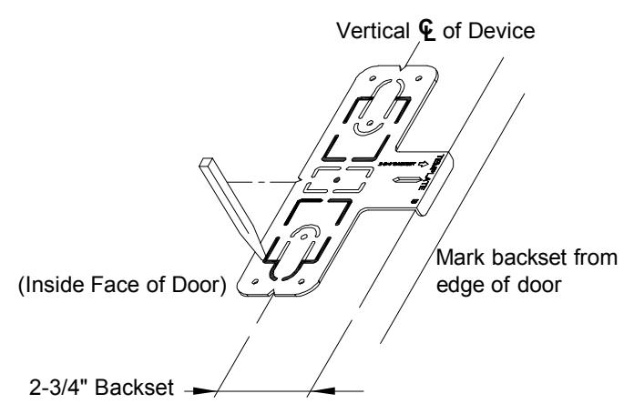
Position template as shown, then mark vertical center line for device center case.
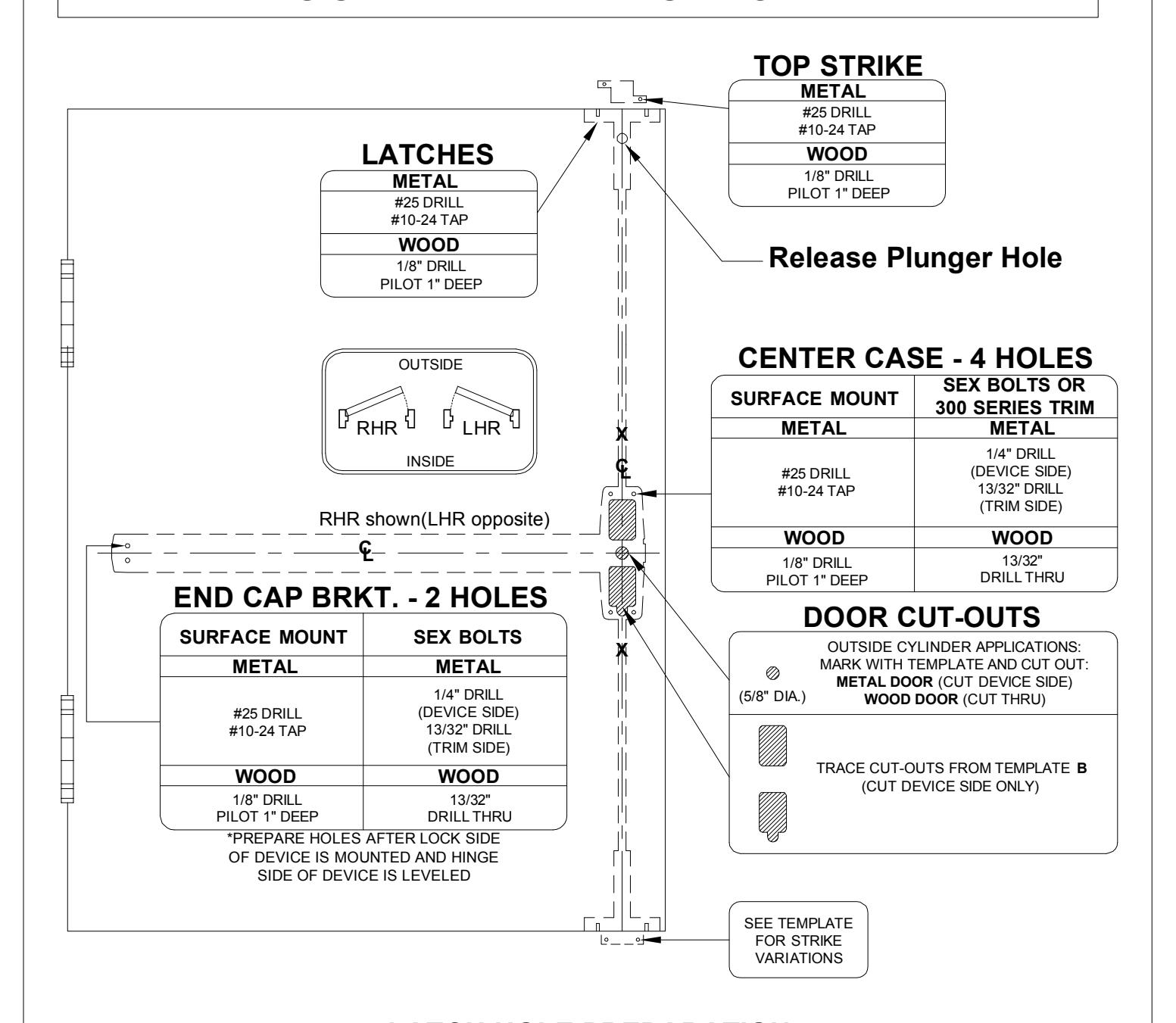
3 PREPARE DOOR FOR DEVICE AND TOP & BOTTOM LATCH.
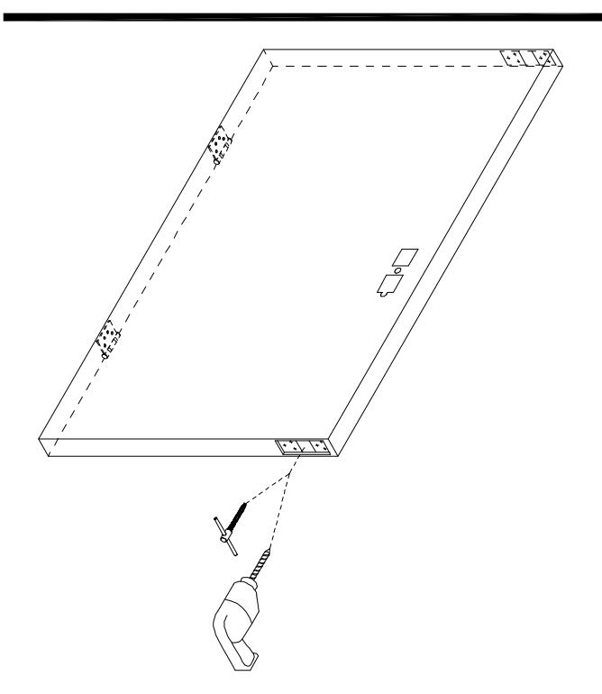
See "DOOR PREPARATION CHART" on page 4 for drill tap, and cut-out information.
4 DRILL TOP OF DOOR FOR
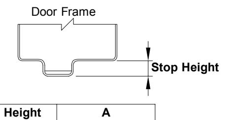
| Stop Height | Α |
|---|---|
| 1/2" | 11/16" |
| 5/8"-Std. | 13/16" |
| 3/4" | 15/16" |
Measure "Stop Height of Door Frame" to decide "Dimension of A".
SCREW. 5
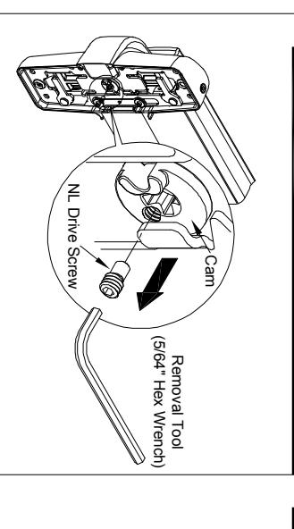
case, the outside cylinder will function only as a Night Latch. center case, when the NL drive screw is left in back of center NL driver screw is factory assembled in cam on back of device
NOTE: 1. DO NOT remove NL drive screw for Pull Plate or Escutcheon with night latch cylinder.
2. REMOVE NL drive screw from back of center case lock and unlock the trim. knob, or thumb piece AND an outside cylinder to when installing trim that has a functional lever,
DETERMINE USE OF NL DRIVE ATTACH RODS TO LATCHES. 6
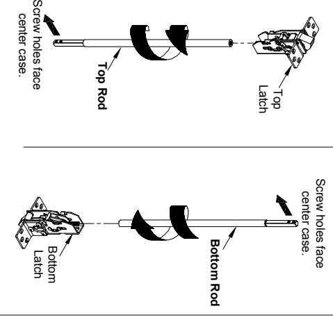
center case. Thread rod onto latch stud until screw holes in rod bars face
INSTALL RODS AND LATCH.
7
1. Install top latch and latch screws from top of door.
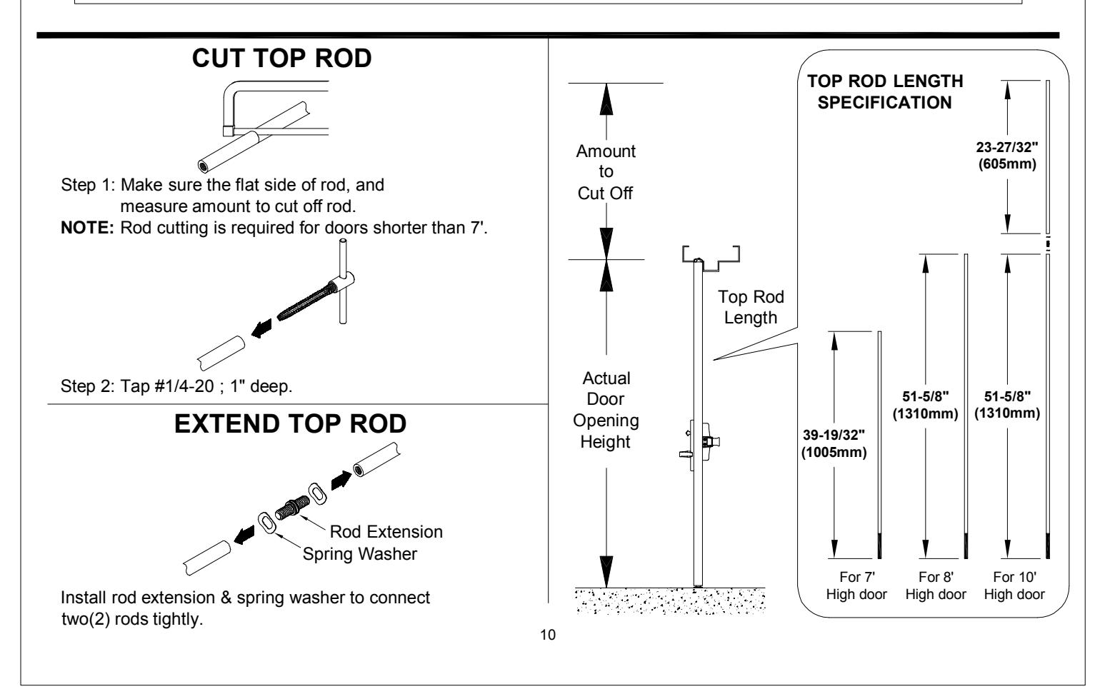
on page 10. EXTEND TOP ROD" See "CUT TOP ROD /
Rod
Latch Screws
- 3. Fine tune the overall length by threading latch in or out of rod. 2. Install bottom latch and latch screws from bottom of door.
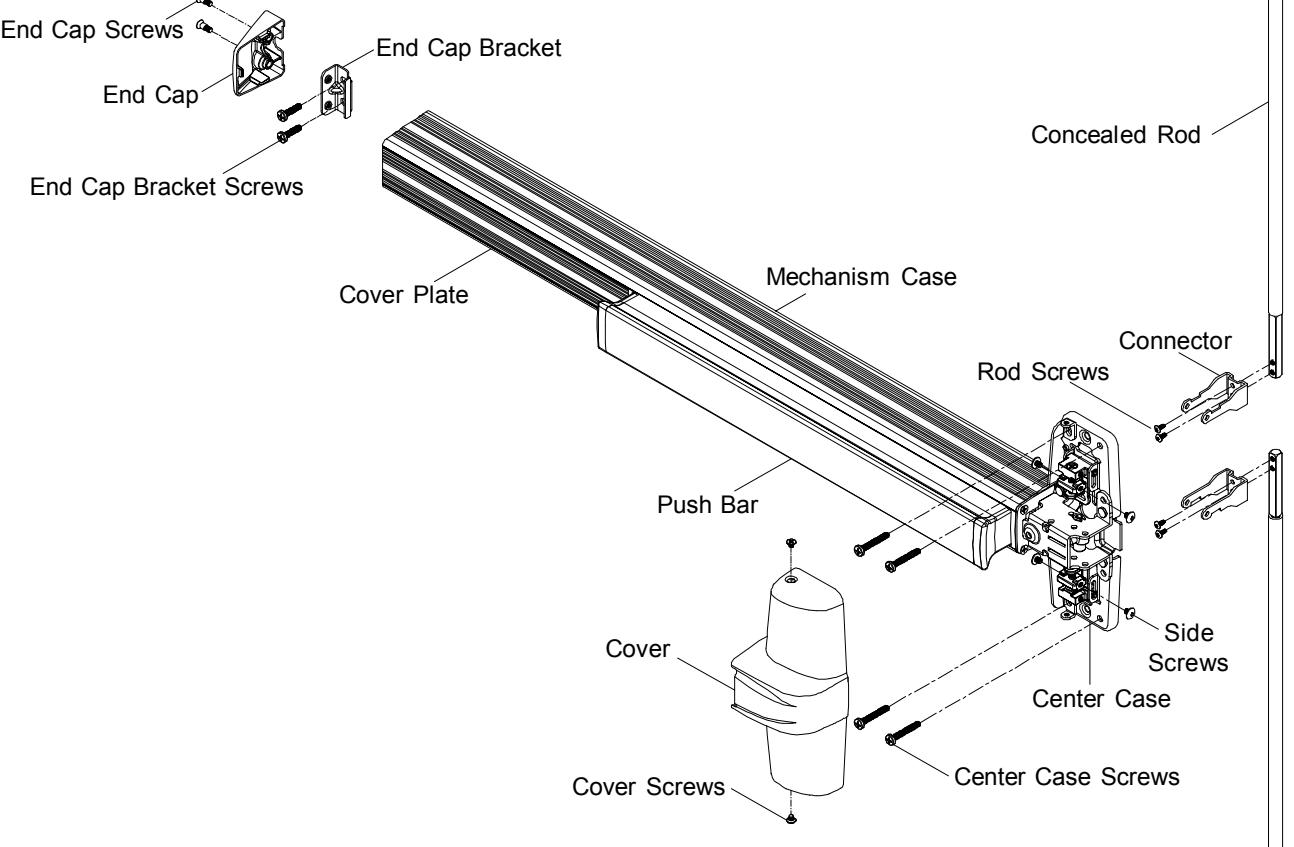
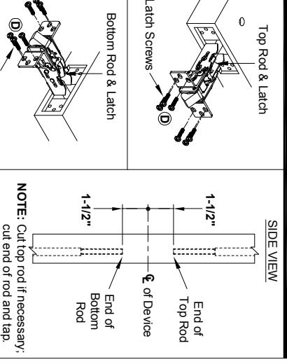
INSTALL CONNECTORS. 8
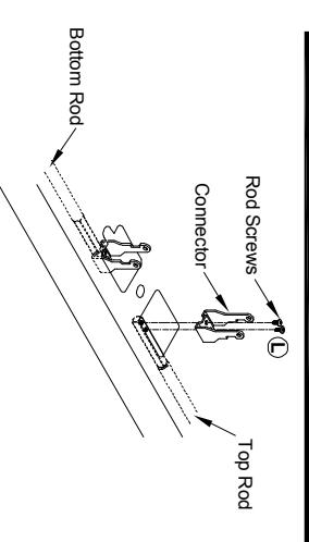
concealed rods with rod screws. After adjusting the lengths, Install connectors on both Notch of of Device LC
Connector
NOTE: Locate notch of connector in top rod toward top of bottom of door. door, and notch of connector in bottom rod toward Bottom Top
INSTALL TRIM (IF USING) AND SECURE DEVICE CENTER CASE TO DOOR. 9
2" Minimum clearance
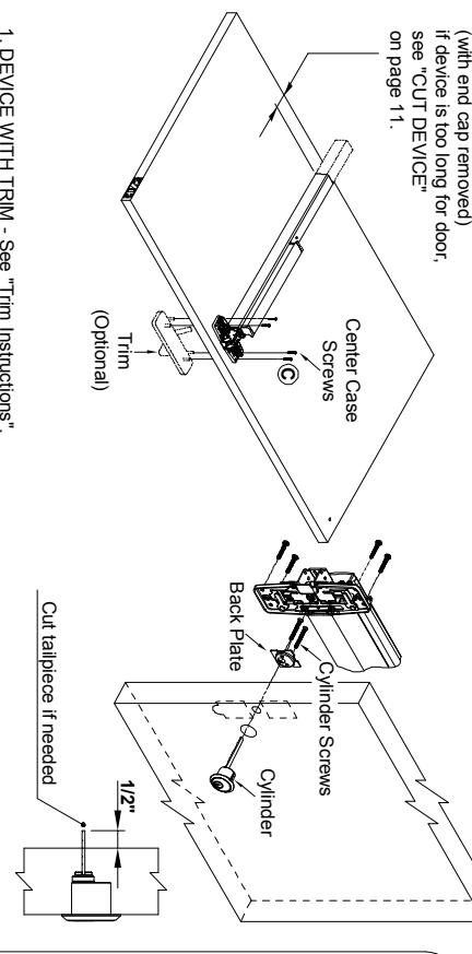
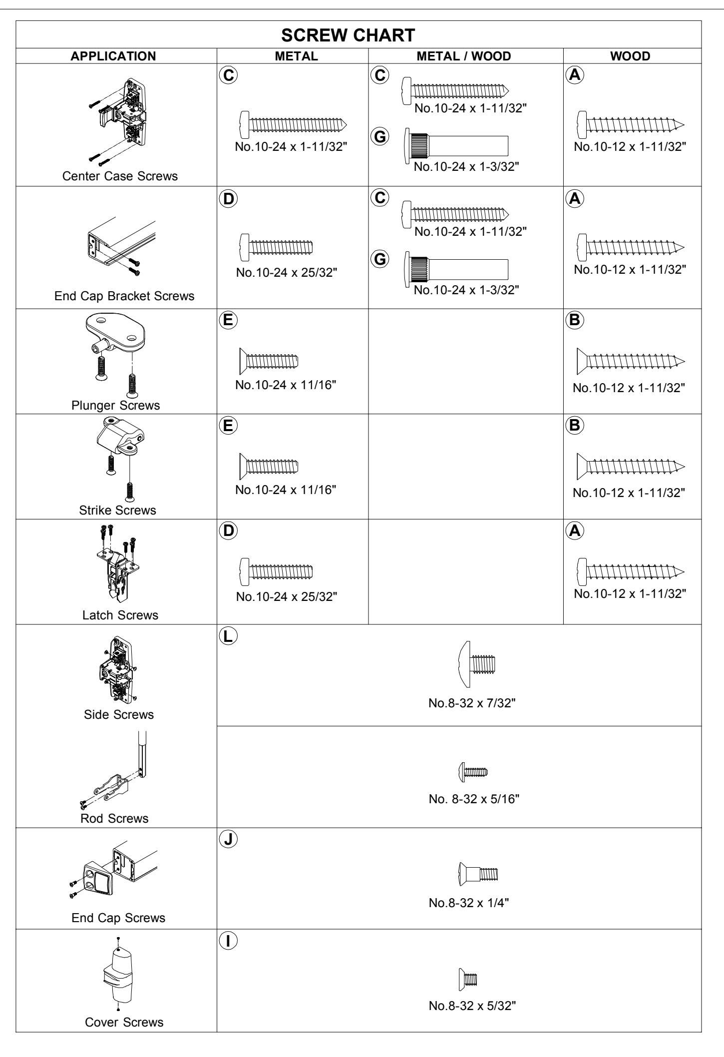
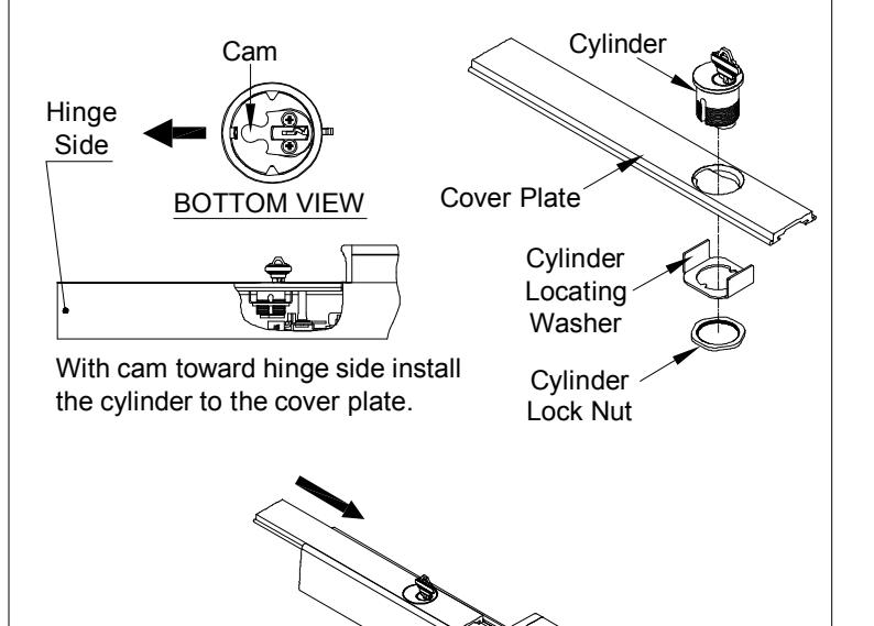
- 1/2" 2. CYLINDER ONLY - Install cylinder with cylinder back plate as shown. Make sure the tailpiece is extending from the inside face of door. Insert tailpiece into cam in the center case and mount it to the door with four(4) center case screws.
- 3. EXIT ONLY Mount center case to the door with four(4) center case screws.
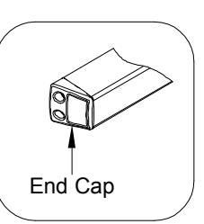
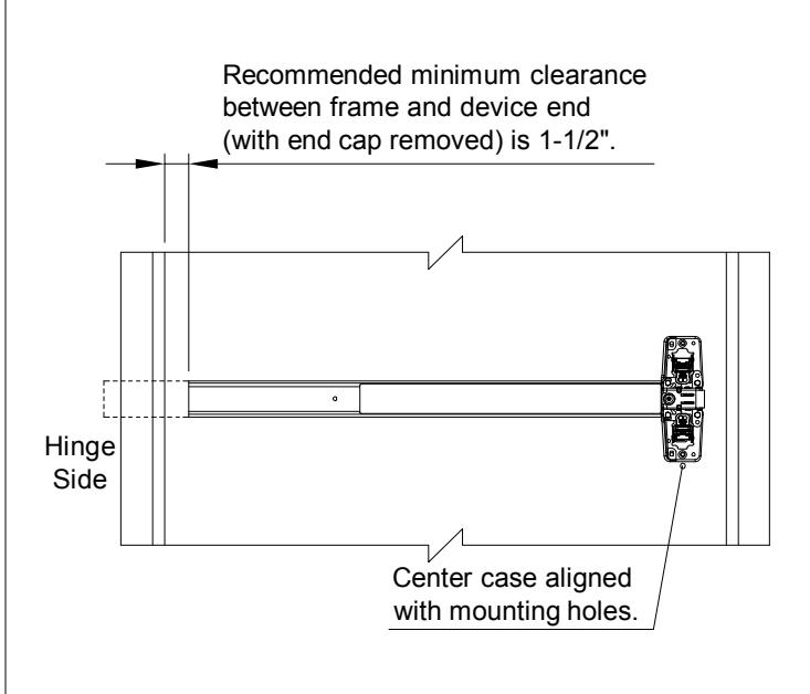
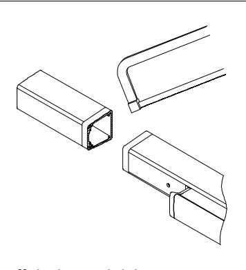
BRACKET AND END CAP. INSTALL MOUNTING 10
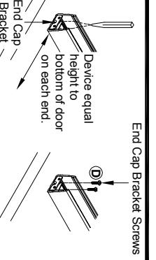
with mounting holes. Center case aligned
screws to door. machine screws. Fasten end cap bracket holes for #10 sheet metal screws or #10-24 Make sure level of device, mark and drill two(2) push bar assembly against mechanism case. 1. Remove cover plate, insert end cap bracket into
NOTE:
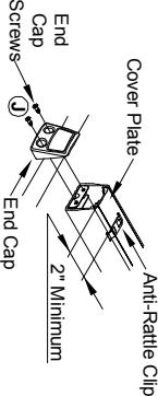
center case.
Install center case with both connectors go
through clearance between retractors and
end cap with two(2) end cap screws. position(2" minimum from end), and attach 2. Insert cover plate, slide anti-rattle clip in
7
INSTALL SIDE SCREWS. 11
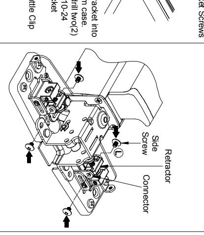
- 2. Apply both sides "side screws" through 1. Make sure both latchbolts are extended.
- NOTE: holes in retractors and tighten. round holes in connector with threaded Both sides of connectors and retractors must install side screws.
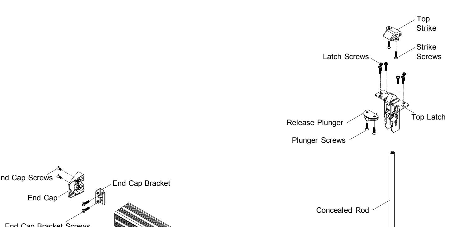
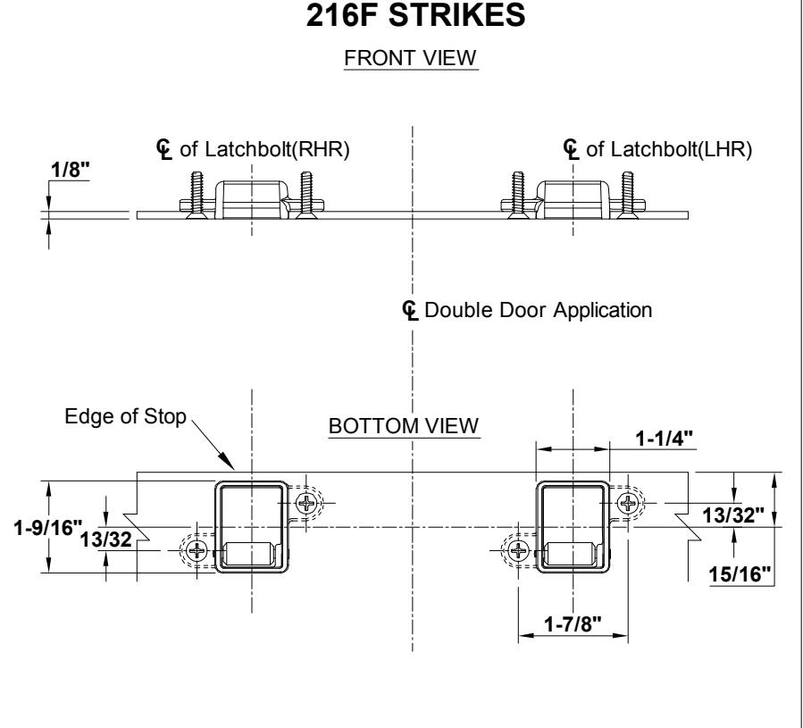
HANG DOOR AND INSTALL TOP 12 STRIKE & RELEASE PLUNGER.
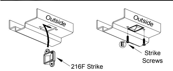
See "FRAME PREPARATION" on page 9 for cut-out and holes. After preparing, install top strike into door frame and mount two(2) strike screws.
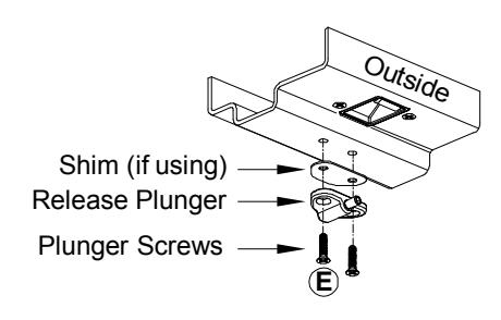
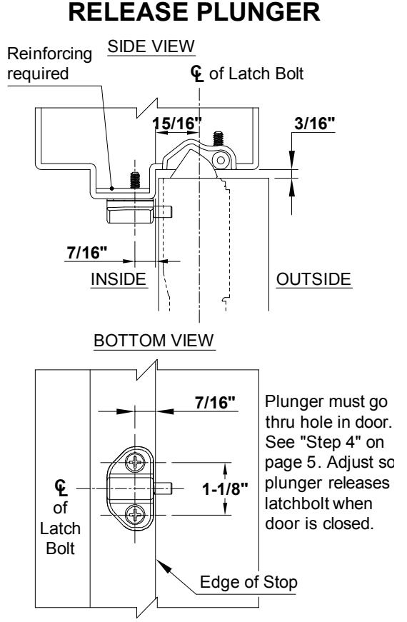
See "FRAME PREPARATION" on page 9 for holes. After preparing, install release plunger with two(2) plunger screws.
15 INSTALL CASE COVER.
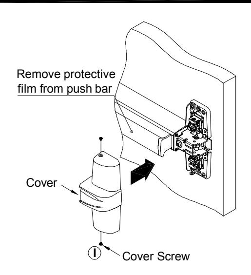
Attach cover to center case with two(2) center case screws.
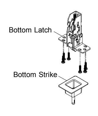
INSTALL BOTTOM STRIKE. 13
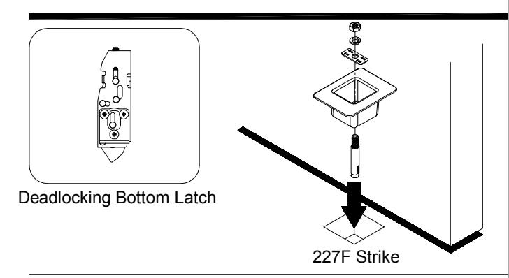
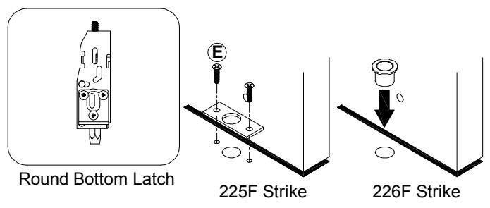
- 1. Mark floor for fasteners, prepare floor according to the type of strike and fastener furnished. Provide clearance in floor for bolt.
- 2. For threshold application:
Provide hole in threshold according to type of strike and fasteners furnished.
14 ADJUST LATCHES AND SECURE TOP & BOTTOM LOCKING SCREWS.
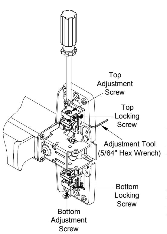
- 1. Depress push bar to retract the latch bolt and open the door.
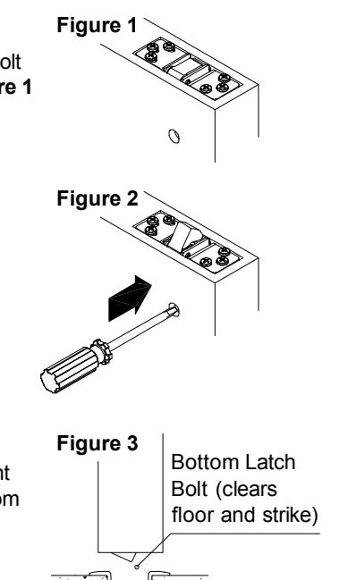
- 2. Check top latch for HOLDBACK (Latchbolt stays retracted in latch case). See Figure 1
- 3. Loose top locking screw.
- 4. Rotate top adjustment screw until top latchbolt is fully retracted.
- 5. Release top latchbolt. See Figure 2
- 6. Check top latchbolt for DEADLOCK (Latchbolt should not push in).
- 7. Rotate top adjustment screw until top latchbolt is in DEADLOCK.
- 8. Tighten top locking screw.
- 9. Depress push bar and retract latchbolt.
- 10. Make sure top latchbolt stays retracted as shown. See Figure 1
- 11. Loose bottom locking screw.
- 12. With top latchblot still retracted, adjust bottom rod by rotating bottom adjustment screw, so latchbolt clears floor and bottom strike in HOLDBACK. See Figure 3
- 13. Release top latchbolt. See Figure 2
- 14. Check bottom latchbolt for DEADLOCK.
- 15. Tighten bottom locking screw.
- 16. Open and close door several times and check device operation and function of DEADLOCK & HOLDBACK.
FRAME PREPARATION
INSTALL FIRE BOLT
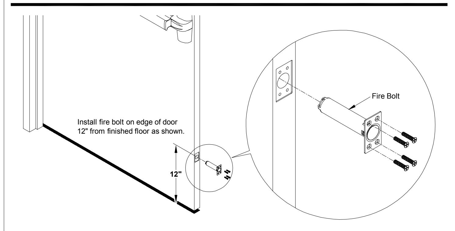
NOTE: Fire rated device with less bottom rod (LBR) applications must use FIRE BOLT.
CUT TOP ROD / EXTEND TOP ROD
OPTIONAL DOGGING
CYLINDER DOGGING
Slide cover plate in position in the mechanism case.
DOGGING CHECK
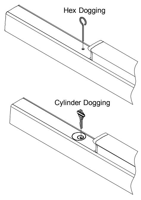
Depress push bar and turn hex wrench or key one full turn for dogging check.
CUT DEVICE (IF REQUIRED)
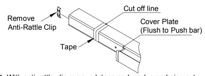
1. With anti-rattle clip removed, tape and mark area being cut.
2. Cut off device and deburr. NOTE: Device must be cut square for proper end cap fit.