ED EF1200 Installation
Open the original PDF document
View PDFED1200/1200F SERIES SURFACE VERTICAL ROD DEVICE
INSTALLATION INSTRUCTIONS
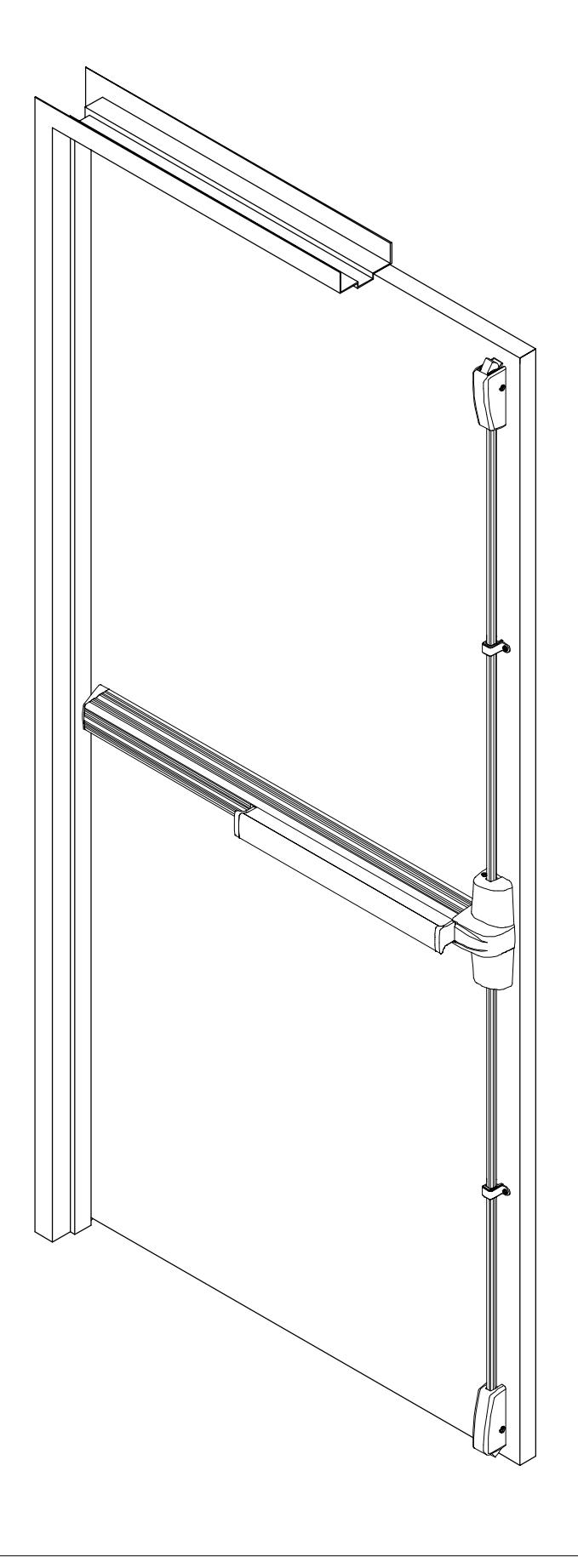
1200 SERIES SURFACE VERTICAL ROD EXIT DEVICE
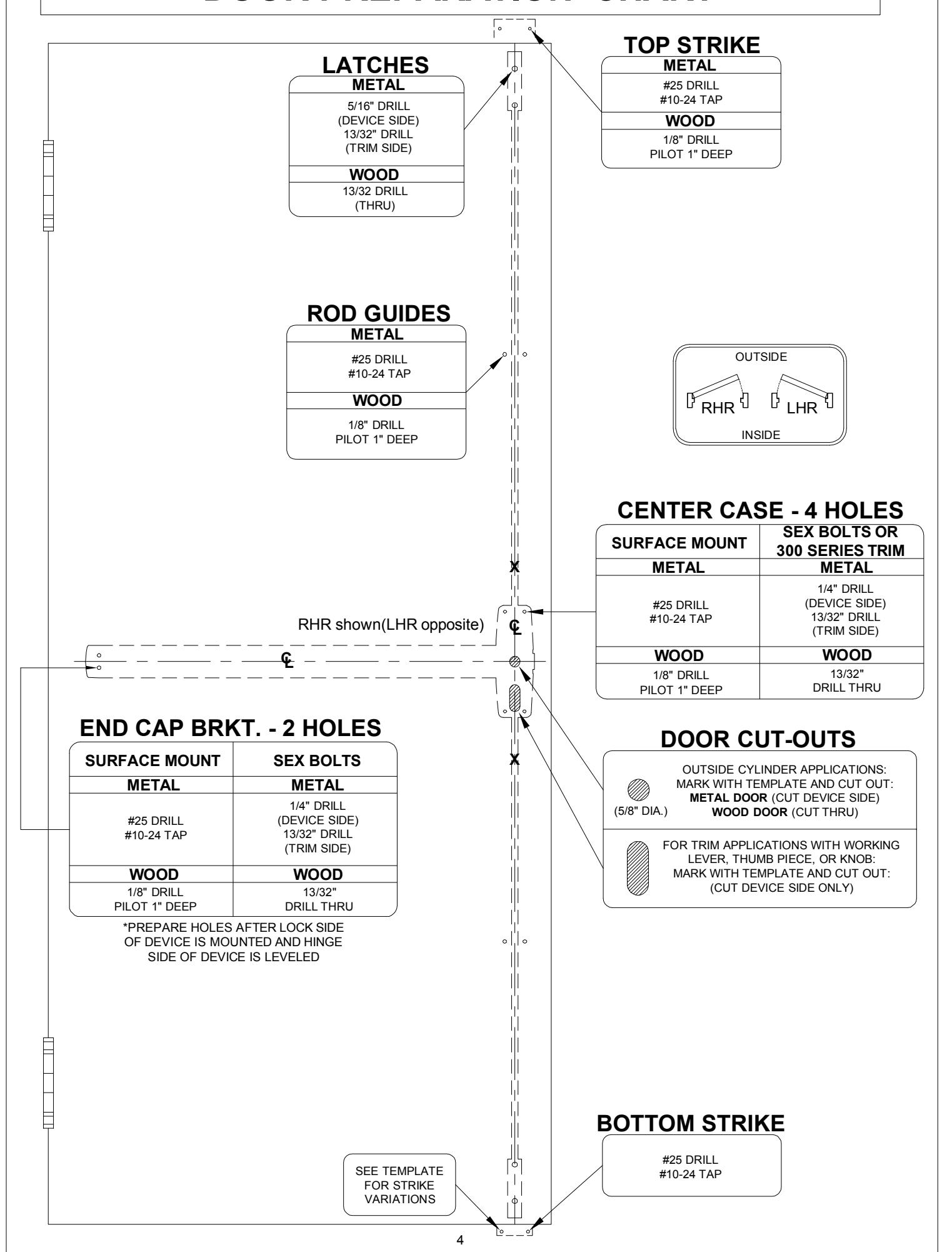
DOOR PREPARATION CHART
CL DRAW HORIZONTAL CENTERLINE ( ). 1
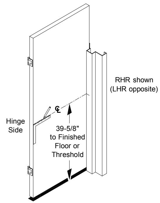
Mark horizontal centerline on inside face of door 39-5/8" from finished floor as shown. (Continue horizontal center line to outside face of door if trim is using)
POSITION TEMPLATE AS SHOWN 2 AND MARK VERTICAL CL .
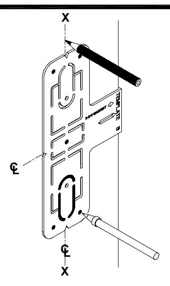
Mark vertical center line X-X above and below horizontal center line. (Mark vertical center line at lock side using same backset dimension on outside face of door if trim is using).
CAUTION: Vertical center lines on both sides of the door should be the same dimension from the edge of the door. Use extra care if edge of door is beveled. Be sure X-X vertical center line is parallel to edge of door.
ALIGN TOP & BOTTOM TEMPLATES ALONG CENTERLINE, THEN MARK AND PREPARE DOOR. 3
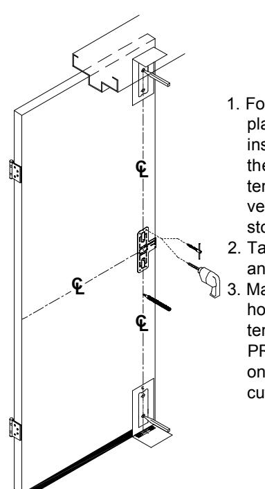
- 1. Fold strike template and place on door stop and inside face of door, so the vertical centerline on template lines up with the vertical centerline on door stop and door.
- 2. Tape template on door stop and the door face.
- 3. Mark centers and drill/tap holes as indicated on the template. See "DOOR PREPARATION CHART" on page 4 for drill/tap, and cut-out information.
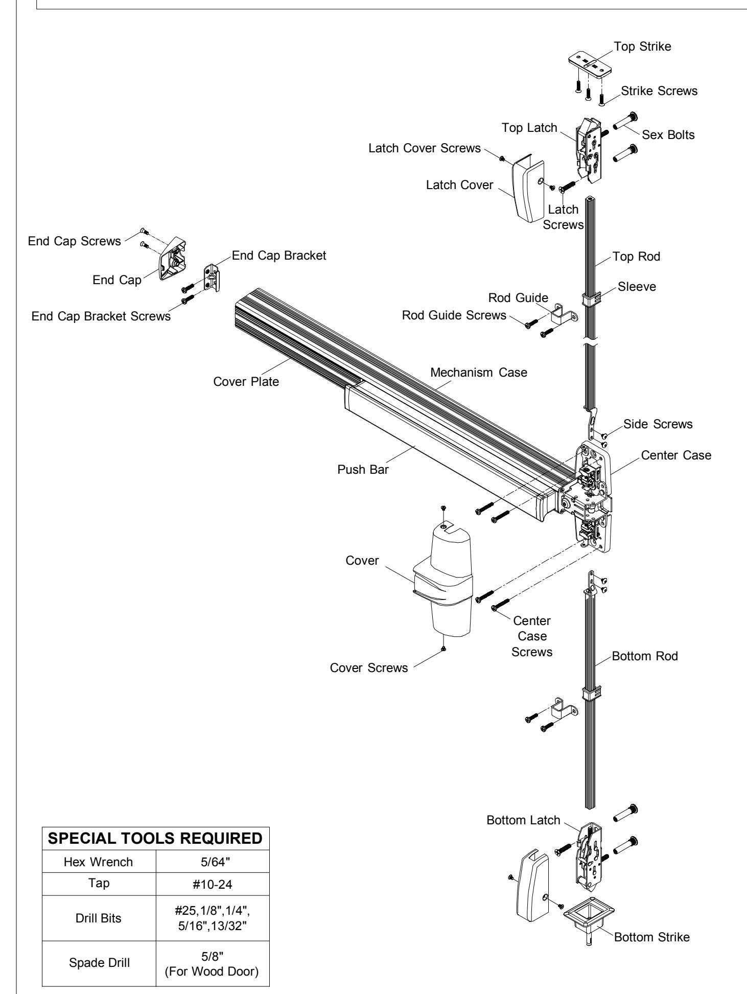
INSTALL TOP STRIKE AND SHIM. 4
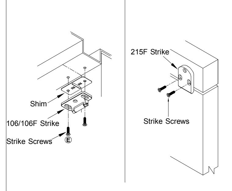
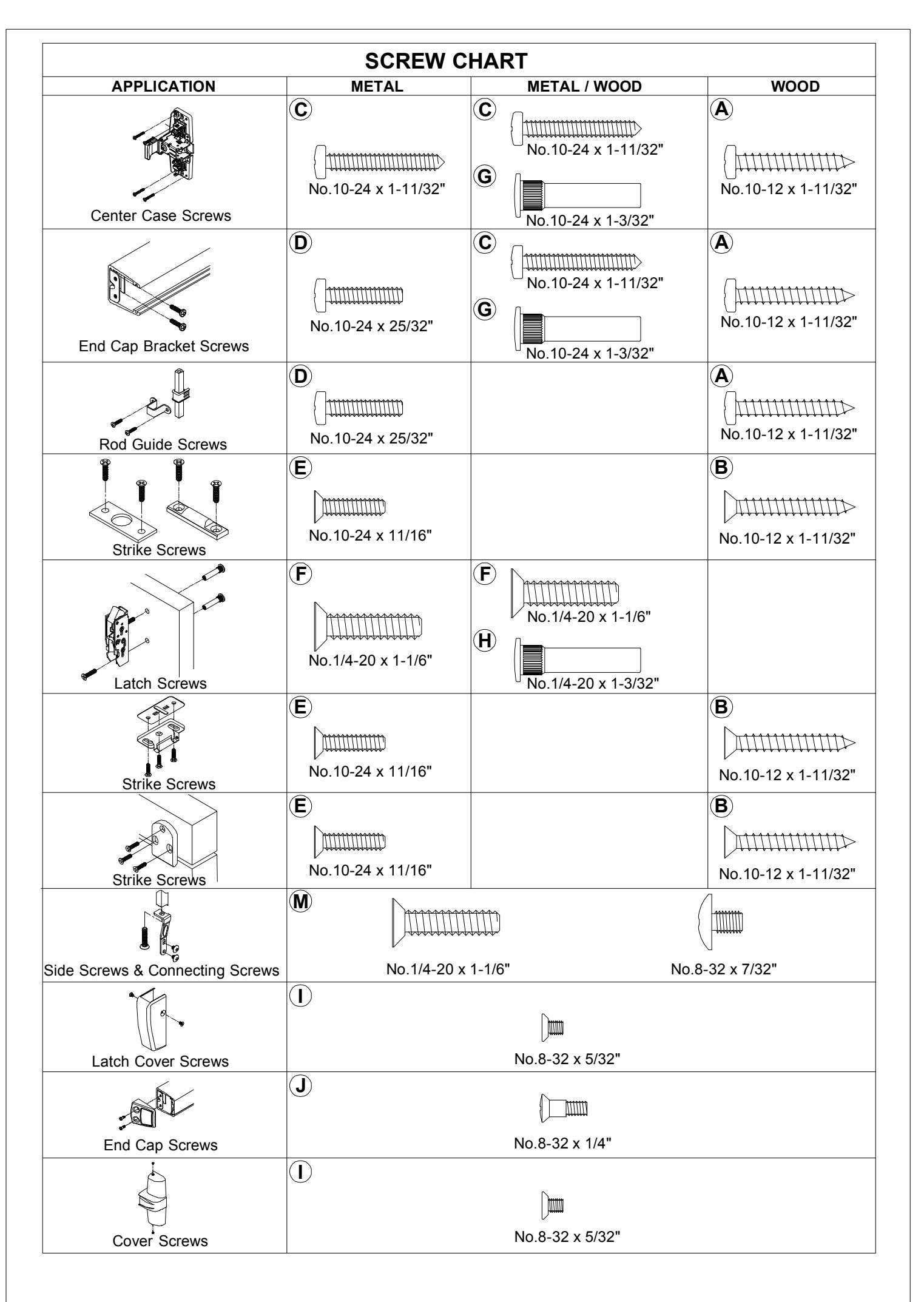
Install a screw through each slot.
5 INSTALL BOTTOM STRIKE.
- For threshold application: Mark floor for fasteners, prepare floor according to the type of strike and fastener furnished. Provide clearance in floor for bolt.
- Provide hole in threshold according to type of strike and fasteners furnished
6 DETERMINE USE OF NL DRIVE SCREW.
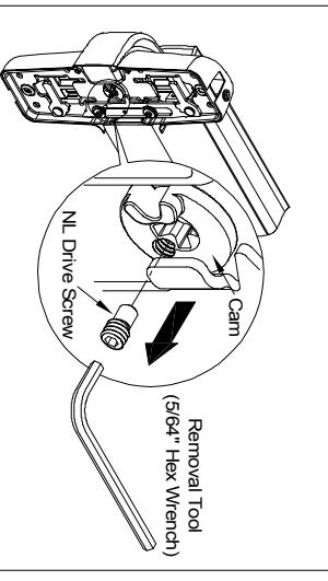
NL driver screw is factory assembled in cam on back of device case, the outside cylinder will function only as a Night Latch. center case, when the NL drive screw is left in back of center
NOTE: 1. DO NOT remove NL drive screw for Pull Plate or Escutcheon with night latch cylinder
REMOVE NL drive screw from back of center case lock and unlock the trim. knob, or thumb piece AND an outside cylinder to when installing trim that has a functional lever
INSTALL TRIM (IF USING) AND SECURE DEVICE CENTER CASE TO DOOR.
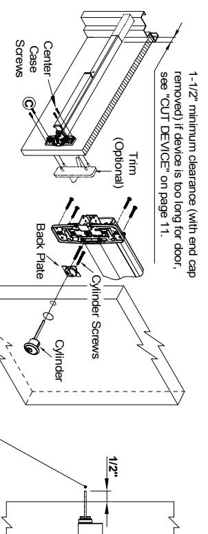
Cut tailpiece if needed
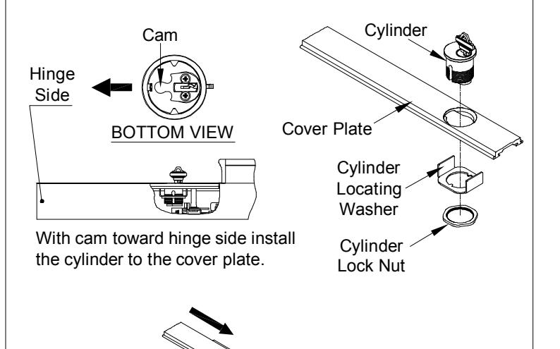
- DEVICE WITH TRIM See "Trim Instructions". CYLINDER ONLY Install cylinder with cylinder back plate as shown. Make sure the tailpiece is it to the door with four(4) center case screws. extending 1/2" from the inside face of door. Insert tailpiece into cam in the center case and mount
- EXIT ONLY Mount center case to the door with four(4) center case screws
For FIRE EXIT DEVICES -
manufacturer has an alternate mounting method. Fire doors and hollow metal doors without reinforcement unless door Sex bolts and support screws are required for composite with steel reinforcement, mount devices with machine screws (wood, plastic and steel covered), wood core, sheet metal
Support Screw Sex Bolt
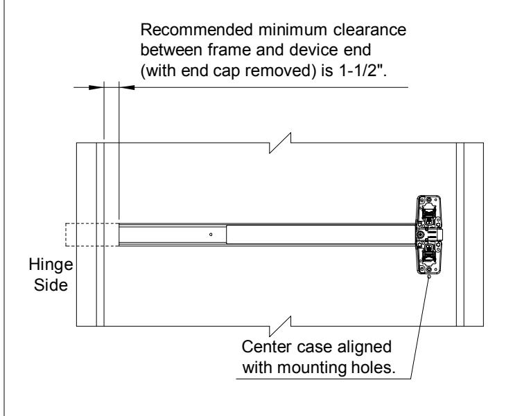
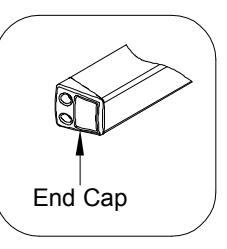
8 INSTALL MOUNTING BRACKET AND END CAP
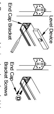
Remove cover plate, insert end cap bracket into hasten end cap bracket screws to door. sheet metal screws or #10-24 machine screws. Level device, mark and drill two(2) holes for #10 push bar assembly against mechanism case.
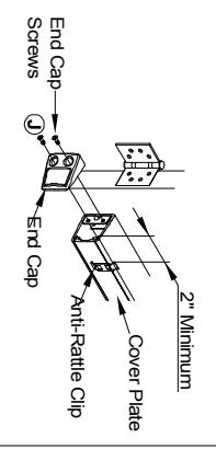
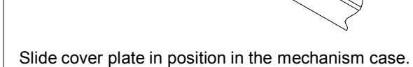
Insert cover plate, slide anti-rattle clip in position (2" minimum from end), and attach end cap with two(2) end cap screws.
9 INSTALL TOP LATCH AND ROD
Amount
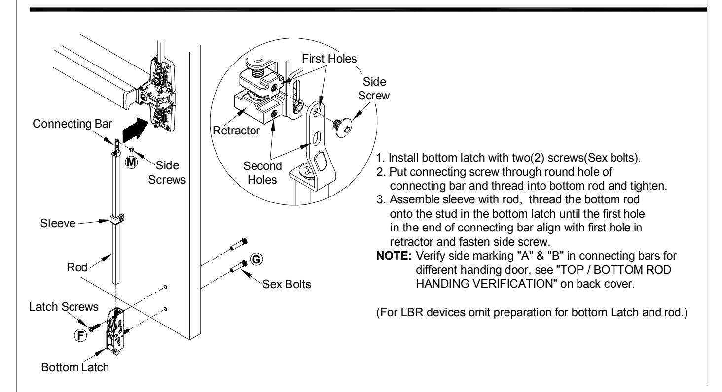
Connecting
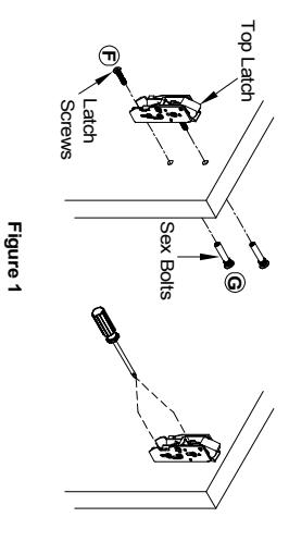
- Install top latch with two(2) screws (sex bolts). See Figure 1 Adjust strike so that device latches without binding
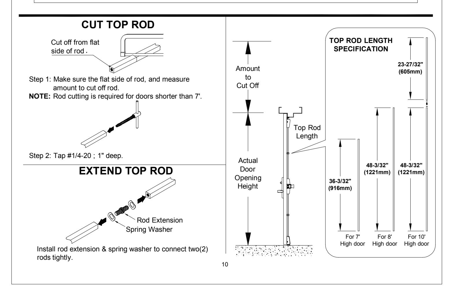
- 2. Determine rod lengths as shown in Figure 2. If necessary; cut end of rod and tap. See
"CUT TOP ROD / EXTEND TOP ROD" on page 10.
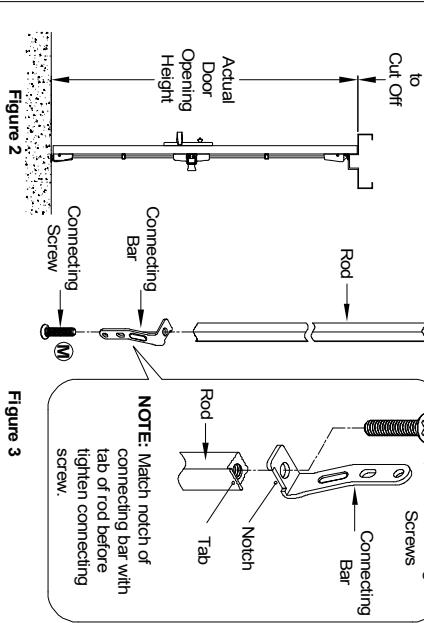
3. Put connecting screw through round hole of connecting bar and thread into NOTE: Verify side marking "A" & "B" in connecting bars for different door handing, top rod and tighten. See Figure 3
see "TOP / BOTTOM ROD HANDING VERIFICATION" on back cover and fasten side screw first hole in connecting bar align with first hole in retractor
4. Assemble sleeve with rod. Thread top rod onto top latch until
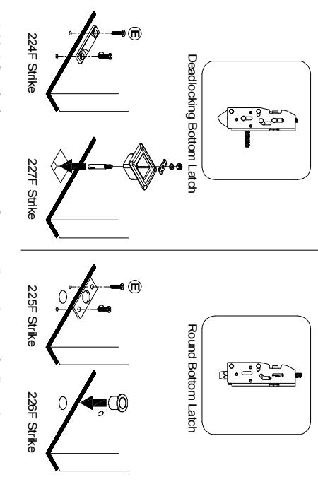
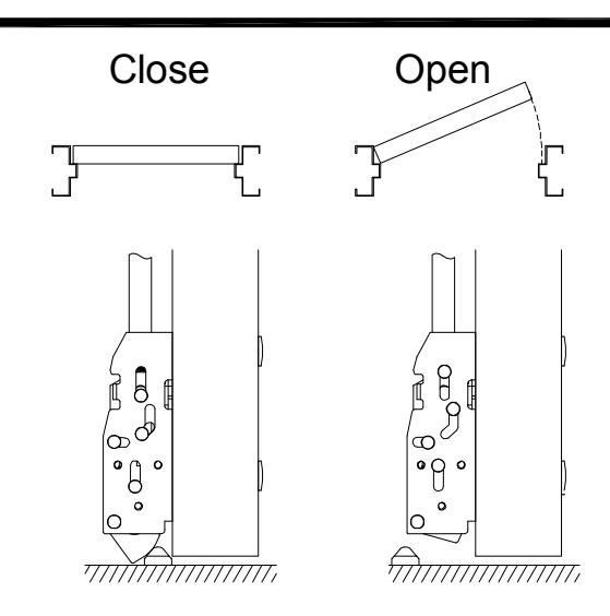
10 CHECK TOP LATCH FOR HOLDBACK AND DEADLOCK.
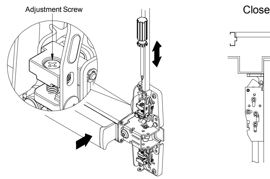
1. Pushing on push bar will retract the latchbolt and open the door. Latchbolt will stay retracted and device is in HOLDBACK. If NO HOLDBACK adjust the screw in top of retractor by screw driver.
2. Fully extended latchbolt should be in deadlock. DEADLOCKED latchbolt cannot be pushed down into the latch housing. If NO DEADLOCK, loose strike screws and adjust strike position.
12 INSTALL BOTTOM LATCH AND ROD.
11 SECURE TWO(2) SIDE SCREWS.
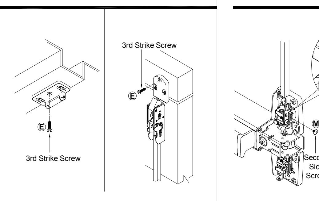
3. Apply third screw in center hole of strike once adjustment is complete.
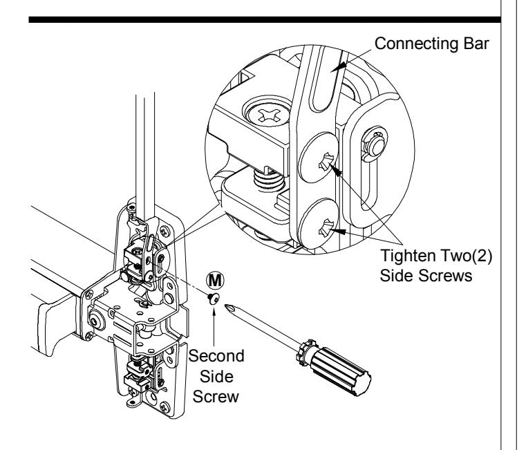
Apply second side screw through second hole in connecting bar with second hole in retractor and tighten two side screws. NOTE: Verify side marking "A" & "B" in connecting bars for different handing door, see "TOP / BOTTOM ROD HANDING VERIFICATION" on back cover.
13 14 ADJUST BOTTOM ROD WITH DOOR OPEN (TOP LATCH RETRACTED).
- 1. Place device in holdback by pushing on push bar. Bottom latch bolt clears bottom strike, adjust retractor by screw driver or readjust rod if needed.
- 2. Secure two side screws when adjustment is completed.
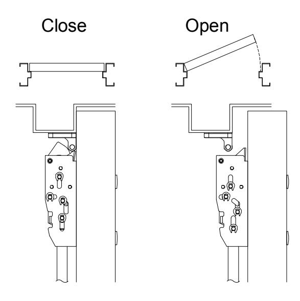
Open and close door a few times and check for deadlocking when door is closed.
INSTALL ROD GUIDES AND COVERS WITH SCREWS.
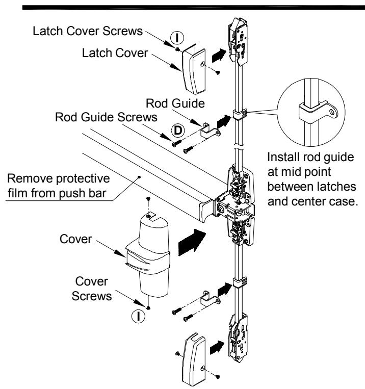
Position rod guides midway between latches and center case, centered on rods. Mark, drill/tap and fasten rod guides with two(2) screws.
INSTALL FIRE BOLT
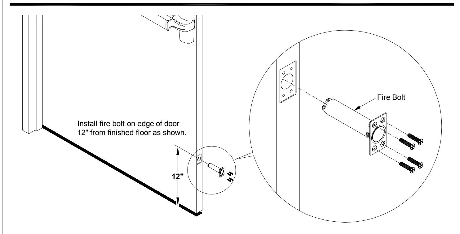
NOTE: Fire rated device with less bottom rod (LBR) applications must use FIRE BOLT.
CUT TOP ROD / EXTEND TOP ROD
OPTIONAL DOGGING
CYLINDER DOGGING
DOGGING CHECK
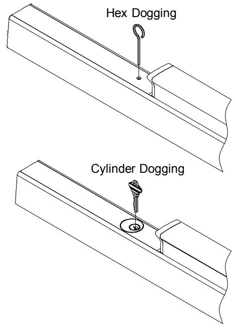
Depress push bar and turn hex wrench or key one full turn for dogging check.
CUT DEVICE (IF REQUIRED)
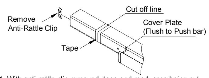
1. With anti-rattle clip removed, tape and mark area being cut.
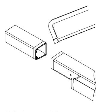
2. Cut off device and deburr. NOTE: Device must be cut square for proper end cap fit.
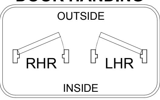
TOP / BOTTOM ROD HANDING VERIFICATION
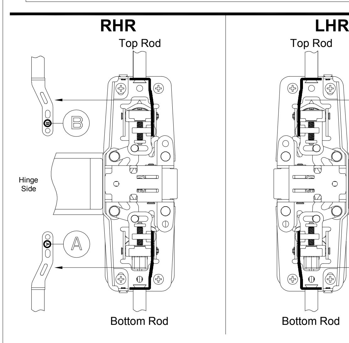
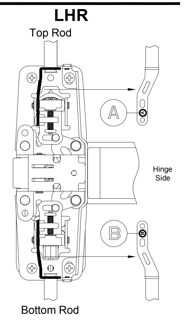
DOOR HANDING