ED EF1100 Installation
Open the original PDF document
View PDFED1100 /1100F SERIES RIM EXIT DEVICE
INSTALLATION INSTRUCTIONS
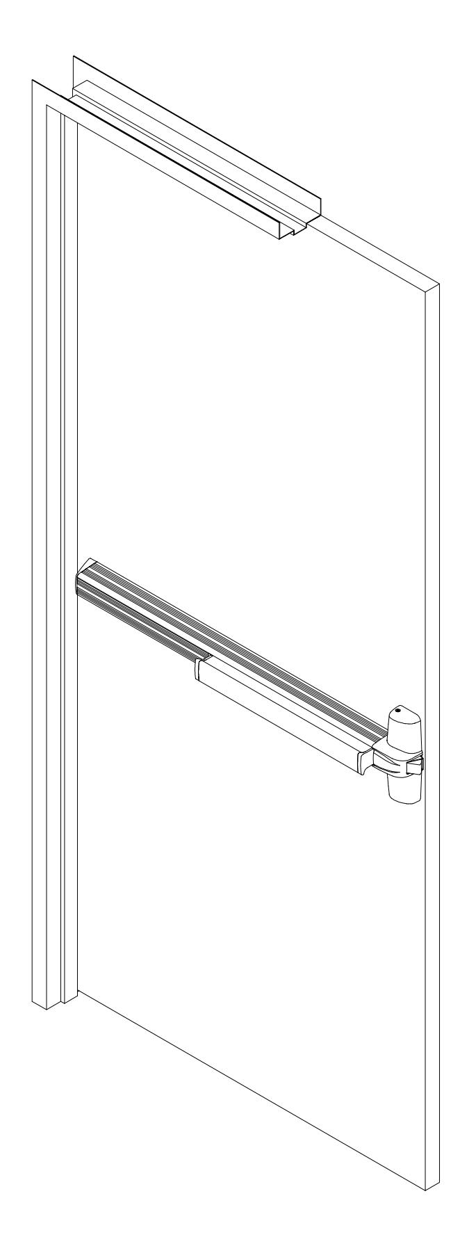
1100 SERIES RIM EXIT DEVICE
|
SCREW
CHART |
||||
|---|---|---|---|---|
| LOCATION | METAL | METAL / WOOD | WOOD | |
| Center Case Screws |
C
No.10-24 x 1-11/32" |
C
No.10-24 x 1-11/32" G No.10-24 x 1-3/32" |
A
No.10-12 x 1-11/32" |
|
| End Cap Bracket Screws |
D
No.10-24 x 25/32" |
C
No.10-24 x 1-11/32" G No.10-24 x 1-3/32" |
A
No.10-12 x 1-11/32" |
|
| Strike Screws |
E
No.10-24 x 11/16" |
B
No.10-12 x 1-11/32" |
||
| End Cap Screws | J | No.8-32 x 1/4" | ||
| Cover Screws |
I
No.8-32 x 5/32" |
|||
| Cylinder Screws |
C
No.10-24 x 1-11/32" |
|||
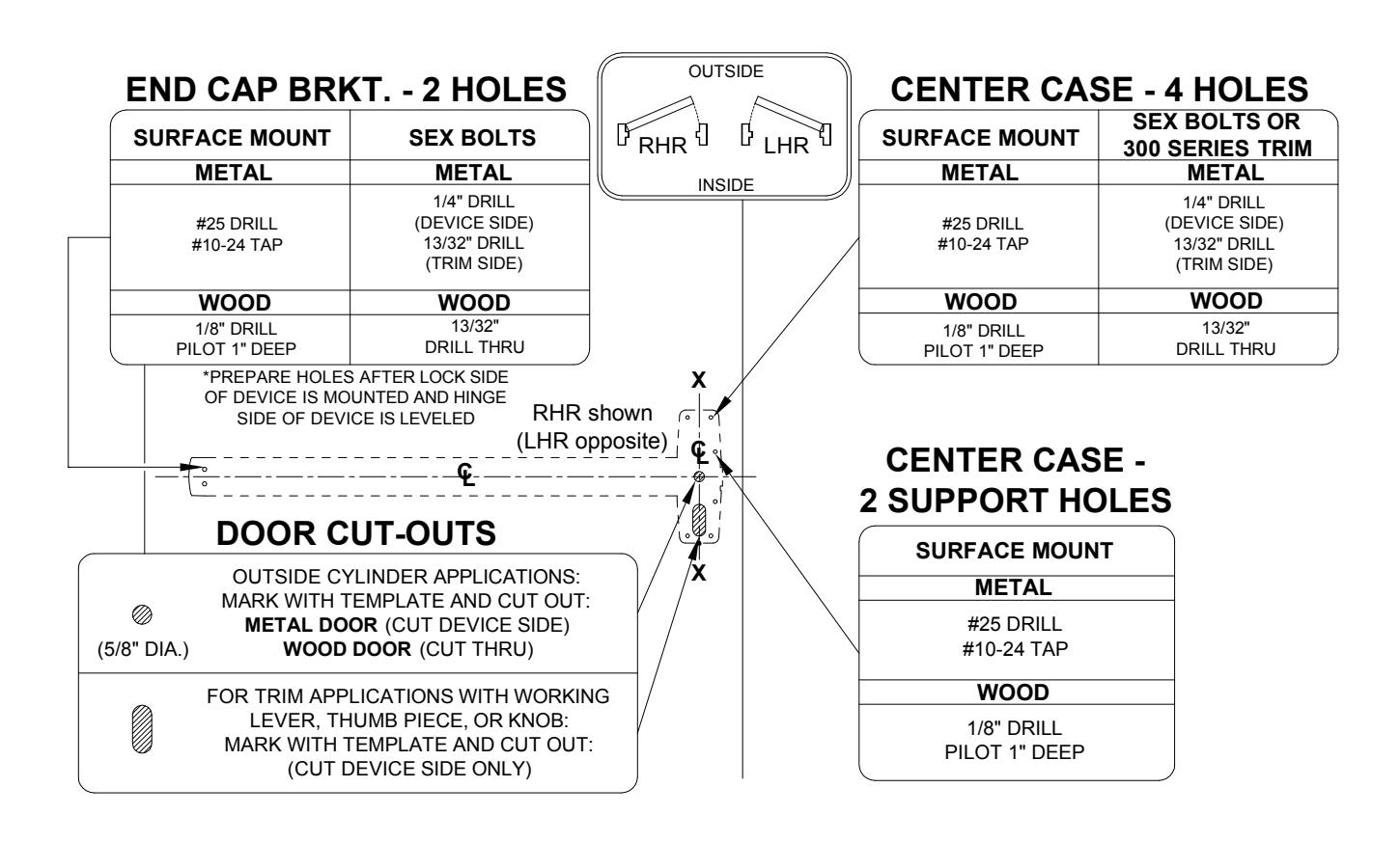
DOOR PREPARATION CHART
TEMPLATE APPLICATION CHART
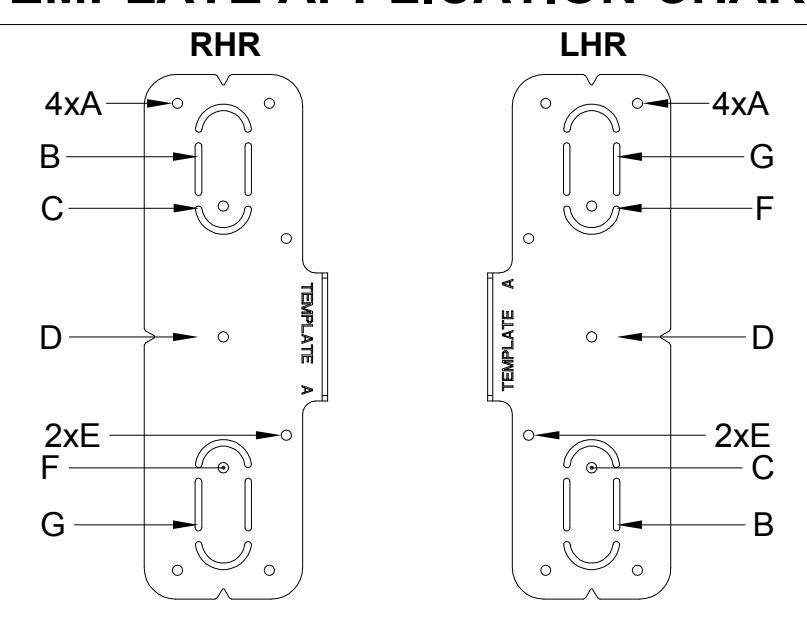
| FUNCTION | RHR | LHR |
|---|---|---|
| 01 | A+E | A+E |
| 02 | A+E+G | A+B+E |
| 08 | A+C+E+G | A+F+E+B |
| 09 | A+D+E | A+D+E |
AND STRIKE CENTERLINE. DRAW HORIZONTAL DEVICE 1
2
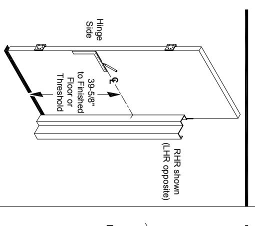
centerline to outside face of door if trim is using). from finished floor as shown(continue horizontal face of door and on lock side door stop 39-5/8" Close door, mark horizontal centerline on inside
TWO(2) SLOTTED HOLES. CENTERLINE ( ) AND MARK ALIGN STRIKE ON HORIZONTAL LC
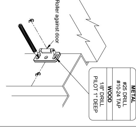
and drill / tap holes as required. centerline on door stop and door. Mark centers centerline on strike lines up with the horizontal and against inside face of door, so the horizontal Use strike as template and place on door stop
through each slot.
Prepare two(2) holes and install a screw
INSTALL STRIKE AND SHIM.
3
AND MARK DOOR. AGAINST STRIKE AND ON POSITION TEMPLATE 4
L
C
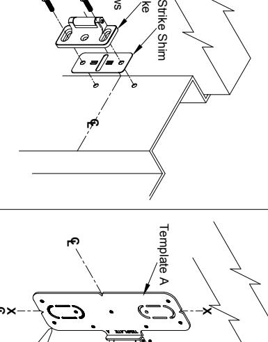
106/106F Strike
Strike Screws
E
Mark centers and drill/tap the required holes as template line up with centerlines on the door. using) to the door so that the centerlines on the Tape "TEMPLATE A"(and trim template if trim is
LC roller of strike. centerline and against Align template on Holes Mark Six(6) LC
indicated on the template.
DEVICE AND TRIM. PREPARE DOOR FOR 5
Be sure X-X vertical centerline is parallel to edge Use extra care if edge of door is beveled. Locate same vertical centerline for both sides. See trim instructions for outside door preparation.
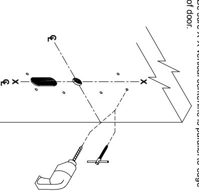
for drill, tap and cut-out information. See "DOOR PREPARATION CHART" on page 3
DETERMINE USE OF NL DRIVE SCREW. 6
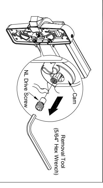
case, the outside cylinder will function only as a Night Latch. center case, when the NL drive screw is left in back of center NL driver screw is factory assembled in cam on back of device
- NOTE: 1. DO NOT remove NL drive screw for Pull Plate or 2. Escutcheon with night latch cylinder. REMOVE
- NL drive screw from back of center case lock and unlock the trim. knob, or thumb piece AND an outside cylinder to when installing trim that has a functional lever,
4
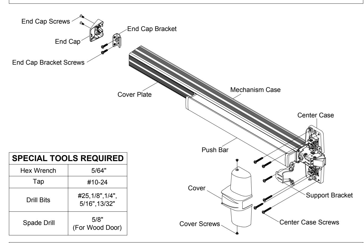
INSTALL TRIM (IF USING) AND SECURE DEVICE CENTER CASE TO DOOR. 7
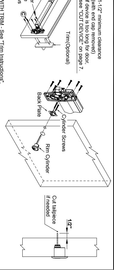
1. DEVICE WITH TRIM - See "Trim Instructions".
Center Case Screws
C
- face of door. Insert tailpiece into cam in the center case and mount it to the door with six(6) center case screws. 2. CYLINDER ONLY - Install cylinder with cylinder back plate as shown. Make sure the tailpiece is extending 1/2" from the inside
- 3. EXIT ONLY Mount center case to the door with six(6) center case screws.
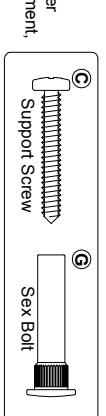
For FIRE EXIT DEVICES
mount devices with machine screws. has an alternate mounting method. Fire doors with steel reinforcement, hollow metal doors without reinforcement unless door manufacturer (wood, plastic and steel covered), wood core, sheet metal and Two(2) sex bolts and support screws are required for composite
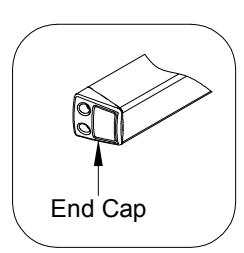
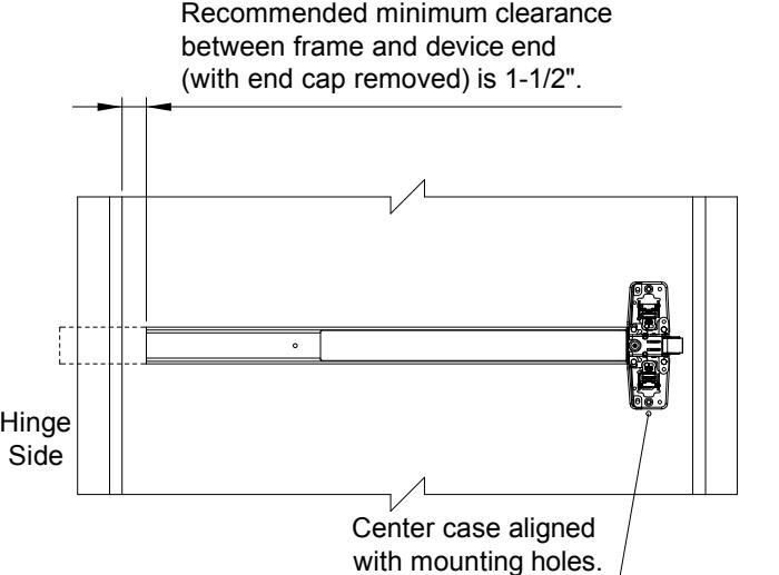
AND END CAP. INSTALL MOUNTING BRACKET 8
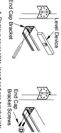
Fasten end cap bracket screws to door. metal screws or #10-24 machine screws. Level device, mark and drill two(2) holes for #10 sheet push bar assembly against mechanism case. 1. Remove cover plate, insert end cap bracket into
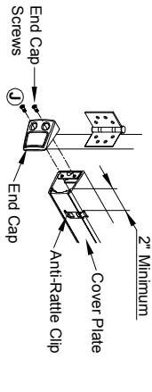
two(2) end cap screws. (2" minimum from end), and attach end cap with 2. Insert cover plate, slide anti-rattle clip in position
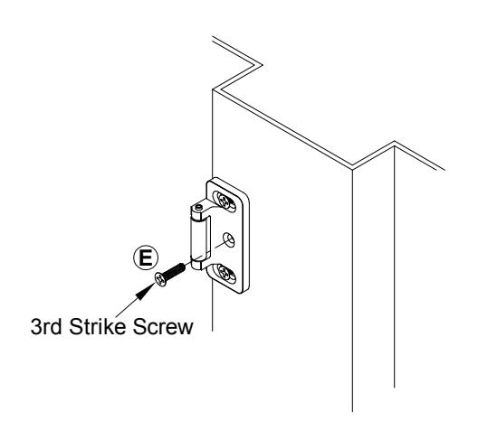
ADJUST AND SECURE STRIKE. 9
INSTALL COVER. 10
Fasten strike to frame and adjust strike so that the device latches tightly without binding, apply third center screw once adjustment is complete.
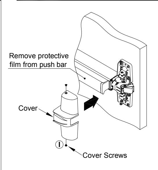
Attach cover to center case with two(2) center case screws.
OPTIONAL DOGGING
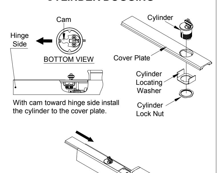
CYLINDER DOGGING
Slide cover plate in position in the mechanism case. for dogging check.
DOGGING CHECK
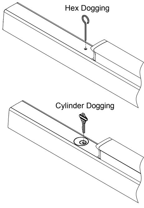
Depress push bar and turn hex wrench or key one full turn
DOUBLE CYLINDER INSTALLATION
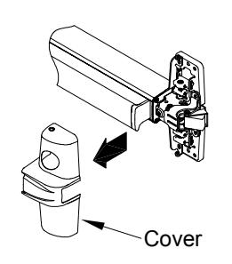
1. Remove cover.
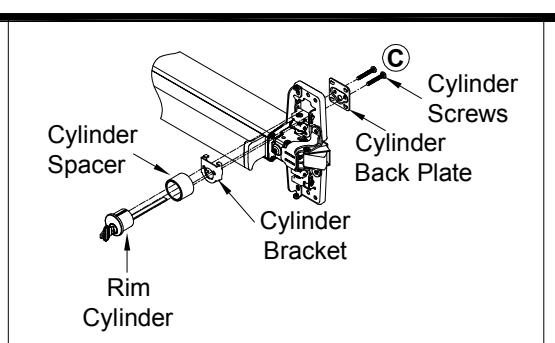
2. Mount rim cylinder to cylinder spacer and bracket and attach assembly to center case with two(2) cylinder screws through cylinder back plate as shown.
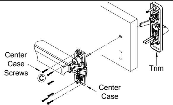
3. Install center case and trim with center case screws. NOTE: See "Trim Instructions" to install trim cylinder.
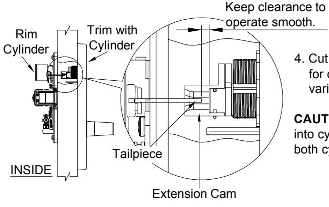
4. Cut off tailpiece if necessary for different door ranges and various cylinder lengths.
CAUTION! If tailpiece is too far into cylinder cam may interfere both cylinders' operation.
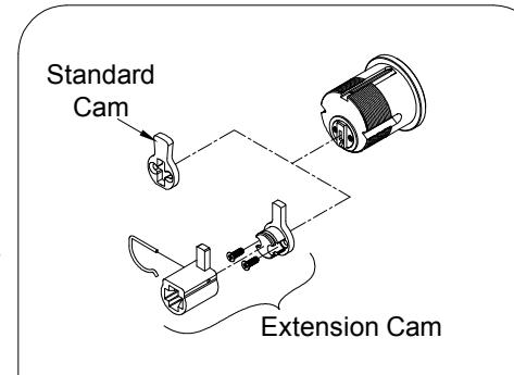
To remove standard cam and replaced with extension cam.
CUT DEVICE (IF REQUIRED)
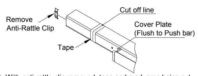
1. With anti-rattle clip removed, tape and mark area being cut.
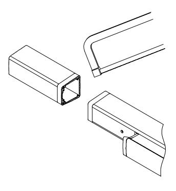
2. Cut off device and deburr. NOTE: Device must be cut square for proper end cap fit.