E75 Standalone Lockset Installation Instructions
Open the original PDF document
View PDF

801 Avenida Acaso, Camarillo, Ca. 93041 • (805) 494-0622 • Fax: (805) 494-8861 www.sdcsecurity.com • E-mail: service@sdcsecurity.com

INSTALLATION INSTRUCTIONS E75 STANDALONE ELECTRONIC LOCKSET
- Keypad Programmable
- 3,000 Users, 32 Temporary Users
- 4 to 6 digit PIN Codes
- Passage Mode Option
- 32 Access Groups, Schedules
- 32 Holidays
- 4 Authority Levels
- Keypad Tamper Lockout
- Mechanical Key Override
- Battery Powered (4AA)
- Blue Backlit Cast Metal Keys
- Weather & Vandal Resistant
- Retrofit existing Lock Door Prep
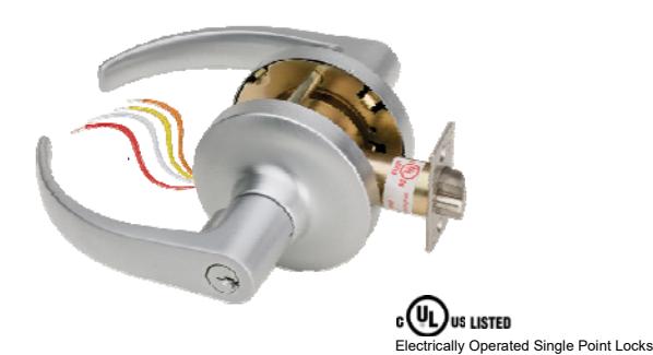
- Motorized SDC Cylindrical Lockset
- Heavy Duty ANSI Grade 1
- Vandal resistant Lever Handles
- Privacy Mode Option (E75KL & E75PL only)
IMPORTANT : It is highly recommended that installers first view the "E75 STANDALONE ELECTRONIC KEYPAD" video available online at https://www.sdcsecurity.com/videos.htm
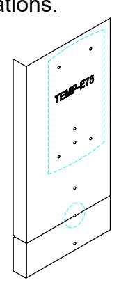
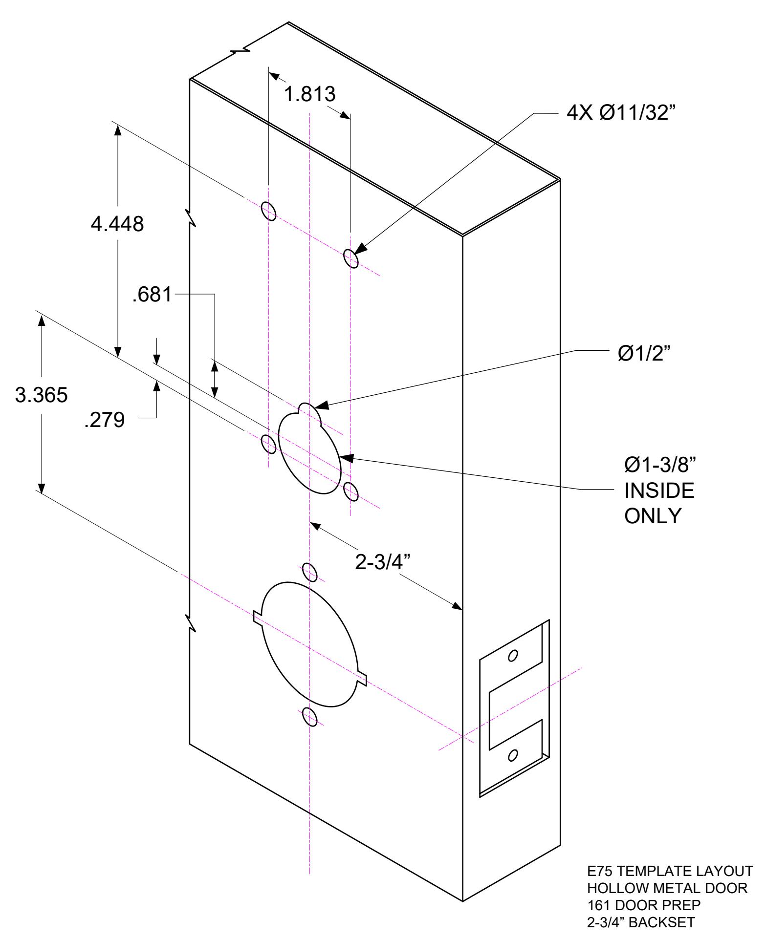
Place provided E75 Template on inside of door to mark hole locations. 1
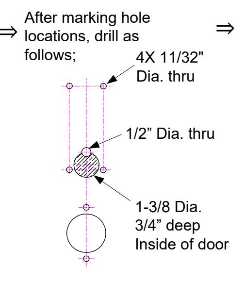
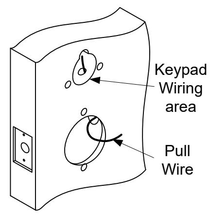
After drilling holes in door, use a 1/4" Butterfly bit, to drill the wire raceway where shown. INSIDE Raceway 1.00" Diameter 5.00" min depth
& Latches, 3hr 'A' Label Fire Doors
- 2 Pass a small pull wire through the raceway hole. This pull wire will be used to bring wires from the lockset hole to the keypad wiring area.
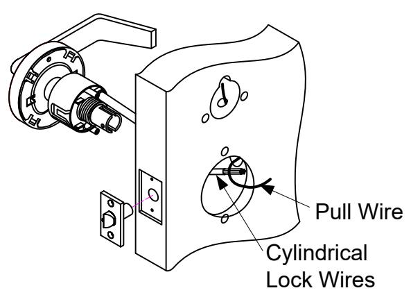
- 3 Install the Lockset. (Refer to lockset instructions)
- Attach the Pull Wire to the Cylindrical Lock Wires. Pull the lock wires up through the raceway as you insert the cylindrical lock.
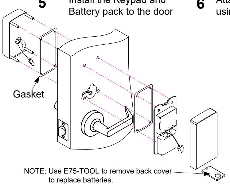
FOR E75KL or E75PL Privacy Locks, skip to Steps 8-10 on the next page. For all other models, follow Steps 5-7 below.
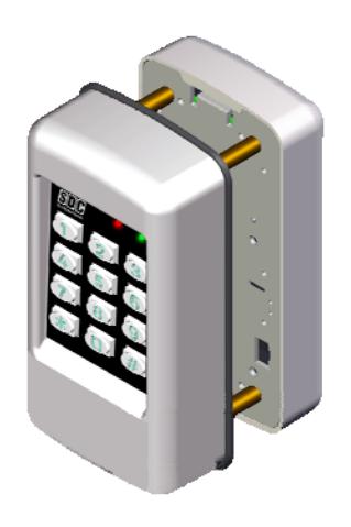
Install the Keypad and
Attach wires from the lockset to the keypad using the chart to the right.
| Function |
From
Keypad |
From
Lockset |
|---|---|---|
|
Motor +
Output - |
RED | RED |
| WHT | WHT |
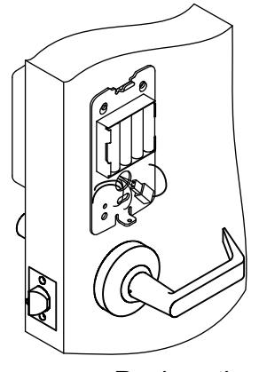
Apply power by plugging in the keypad's 2-wire connector to the battery pack connector. The left LED will flash rapidly as shown below followed by 3 beeps.
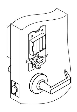
Replace the cover over the battery pack by first hooking the top and gently pressing the bottom
Specifications
Power 4AA Batteries (Alkaline only) or
External 12VDC Power @ 30mA
1 Request-To-Exit Inputs
1 Door Position Switch
SPDT Contacts 1A @ 30VDC Relay Output -20° F to +130° F (-30° C to +54° C) Temperature
Humidity 5% to 95% non-condensing
Latch Bolt 9/16" Backset 2-3/4"
4-7/8" ANSI A115.2 Strike 1-3/4" to 2-1/8" Door
Thickness
Additional Wire Connections (Optional)
Request-To-Exit Input BLU(N/O) / BLK(COM)
Door Position Switch Input = GRY / BLK(COM)
Auxiliary Relay Output ORG (N/C)
WHT(COM) YEL(N/O)
System Reset BRN / BRN
12VDC External Power RED(+) / BLK(-) (22AWG)
(NOTE: Ext. pwr harness ships separately in box)
Steps 8-10 for E75KL and E75PL Privacy models only,
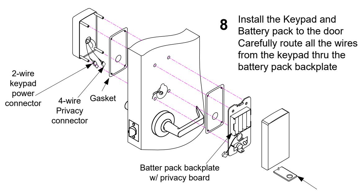
-
a. Connect the 4-wire privacy cable to the back of the privacy board.
9
- b. Attach wires from the lockset to the keypad using the charts below.
| Function | From | From |
|---|---|---|
| Keypad | Lockset | |
|
+
Motor _ Output |
RED | RED |
| WHT | WHT |
| Function | From | From |
| Keypad | Lockset | |
|
Privacy
Reset |
BLUE | WHT/RED |
| BLACK | YEL/RED | |
NOTE: Use E75-TOOL to remove back cover to replace batteries.
10 Apply power by plugging in the keypad's 2-wire connector to the battery pack connector. The left LED will flash rapidly as shown below followed by 3 beeps.

Replace the cover over the battery pack by first hooking the top and gently pressing the bottom, ensuring that the privacy button and LED are properly aligned with the cover holes.
Additional Wire Connections from Keypad (Optional)
Door Position Switch Input = GRY / BLK(COM)
Auxiliary Relay Output = ORG (N/C)
WHT(COM) YEL(N/O)
Factory Reset = BRN / BRN
12VDC External Power (NOTE: Ext. pwr harness ships separately in box)
= RED(+) / BLK(-) (22AWG)
Quick Start Programming Instructions E75 EntryCheck TM
For a complete list of lock programming functions, including programming for the E75KL/E75PL Privacy Lock, refer to the E75 Programming Guide included with this lock.
Test the Lock Operation
To test lock operation before initialization, enter *741 . This temporary code will unlock the E75 for testing purposes. Once a lock initialization has been performed, this code is no longer active until a hardware reset is performed which will erase all the users and return the E75 back into the uninitialized factory default condition.
Lock Initialization
When the lock is first installed or after a factory reset has been performed, the E75 must be initialized with a 4-digit lock ID before you will be allowed to enter programming mode.
To Initialize Lock:
Press #9* 123456# 0001#
The above example enters a Lock ID of 0001. If multiple locks are used it is recommended that each lock have its own Unique Lock ID (0002, 0003, etc.). This is required when using the E7 Management Software.
User Programming
NOTE: You must first enter programming mode to perform any other function. 20 seconds of inactivity will automatically exit you from programming mode and return you to operational mode.
Enter Programming Mode:
Press #9# 01# 123456#
User 01 with default PIN Code 123456 is the administrator and has full programming rights.
Add a User PIN Code (4-6 digits): 01# User No.# PIN Code # Pin Code # Group No.#
Example: Press 01# 04# 5050# 5050# 06#
You have just added User #04 with a PIN of 5050 to unlock the door.
User 4 has been assigned to group 06 (24/7 access).
Add a Single Card: 06# User No.# Present Card
Example: Press 06# 04# Present Card
You have just added a card to User #4.
User 4 has also be assigned to group 06 (24/7 access).
Prox Units Only
Add a Sequential Batch of Cards: 08# Starting User No.# No. of Cards# Present 1st Sequential Card
Example: Press 08# 05# 10# Present Card
You have just added (10) proximity card for User #'s 05 to 14.
All users has also be assigned to group 06 (24/7 access).
Exit Programming Mode: **#
Press **#
Test the lock by pressing 5050#, or present a valid prox card to the reader (prox units only).
Additional E75 Programming
Refer to the E75 Programming Guide for a complete list of lock programming functions.
Change a User PIN Code: 03# User No.# New PIN Code # New Pin Code #
Example 1: Press 03# 01# 123123# 123123#
You have just changed the Administrator's Pin Code to 123123
NOTE: The Administrator's PIN code must be 6 digits in length. All other PIN codes may be 4-6 digits in length
Example 2: Press 03# 04# 1220# 1220#
You have just changed User #04's Pin code to 1220
Delete a User: 02# User No.# Example: Press 02# 04#
You have just Deleted User #04
Set Entry Mode : 05# Mode #
Example 1: Press 05# 1#
Unlock the door either by entering a (PIN + #) or presenting card.
Example 2: Press 05# 2# Unlock the door by presenting a valid card. Example 3: Press 05# 3#
Unlock the door by presenting card plus the associated user code (PIN + #).
Mode = 1 PIN or Card (default)
2 Card Only 3 Card AND Pin
Set Unlock Timer: 21# Seconds#
Unlock timer is set for 03 seconds. (default)
Example: Press 21# 03 # Seconds = 03-20
Beep on Key Press : 62# Status #
Example 1: Press 62# 1# Status = 0 Disabled
The E75 will beep each time you press a key. 1 Enabled (default)
Set the Date: 30# MMDDYY#
Example: Press 30# 011513 # The date is set for January 15 th 2013 MM = 2 digit Month DD = 2 digit Day YY = 2 digit Year
Set the Time: 31# HH MM# Example: Press 31# 1320 # HH = Hours (24hr format) MM = Minutes (24hr format)
The time is now set to 1:20 PM.
Clear all Programming : 99# 000000 #
Example 1: Press 99# 000000 #
All user codes are erased and settings are set to factory defaults. The Administrator Pin Code and Lock ID are not cleared.
Resetting the E75 to Factory Settings
Warning!! This procedure will preform a hardware reset and will erase all the users and custom settings returning the E75 back into the uninitialized factory default condition.
- 1) Remove power (Unplug the battery pack)
- 2) Short and hold the 2 Brown Reset wires together
- 3) Apply power. (Plug in the battery pack)
The left LED will light RED for a few seconds, followed by a flashing RED/GRN. When initialization is complete, you will hear 3 beeps.
- 4) Disconnect and insulate the Brown Reset wires.
- 5) Return to Page 4 of these instructions to initialize the lock.