E1S Installation Instructions for 790-900_790-915 – I-CS00166
Open the original PDF document
View PDF

E1S – Exposed Switch
Door and Frame Preparation
For a grout filled frame, install a Mortar Box (HAGER 430). Failure to do so will void the hinge warranty.
- 1. Prepare the door and frame for installation using the standard installation instruction sheet furnished with the hinge, but do not attach the hinge at this time.
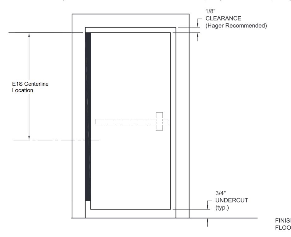
- 2. Using the hinge length; utilize Figure 1, Figure 2 and the table below to find the correct hole center mark location for your door and frame. Dimensions below are based on Hager's standard E1S centerline locations and the industry standard of 1/8" clearance between the top edge of the door opening and the top edge of the door.
|
Hinge
Length |
E1S
Centerline Location |
|
|---|---|---|
| 79" | 41 1/2" | |
| 83" | 43 1/2" | |
| 85" | 45 1/2" | |
| 95" | 55 3/8" | |
| 119" | 79 1/8" | |
Figure 1
- 3. Drill a 1/2" (5/8" max.) diameter access hole in both the frame and the door at the locations determined in step 2. After drilling, deburr the holes to prevent damage to the wire leads. If a shim is utilized to install the hinge, drill a corresponding 1/2" diameter access hole in the shim .
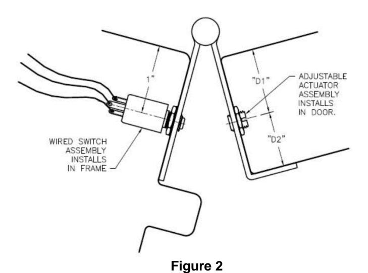
- 4. Locate the wired switch and install it into the threaded hole of the hinge leaf that will be mounted to the frame . Screw the switch into place from the back of the hinge so that the threaded portion is flush with the front face of the leaf (the black plastic plunger will extend 1/8"). Tighten the jam nut against the back of the leaf to secure the switch.
- 5. Locate the adjustable actuator and install it into the threaded hole of the hinge leaf that will be mounted to the door . Screw the actuator into place from the back of the hinge so that the end is flush with the front face of the leaf. Tighten the jam nut against the back of the leaf to secure the actuator.

Installation
- 1. Attach the hinge to the door per the standard installation instruction sheet supplied with the hinge.
- 2. Connect the system wiring to the appropriate leads of the switch as shown in Figure 3. Insulate the bare end of any unused wires.
- 3. Carefully slide wires back through the access hole making sure they are placed so they will not be cut or pinched as installation is completed. Attach the hinge to the frame per the standard installation instruction sheet supplied with the hinge.
- 4. The position of the actuator should activate the switch properly for most typical square-edge door and frame combinations. Certain factors such as door alignment may slightly affect the switch after installation. Check the circuit to make certain the switch is opening/closing as desired. If necessary, the actuator position can be adjusted to possibly compensate for these factors. Loosen the jam nut and screw the actuator in or out to the desired position, then retighten the jam nut. (The door must be removed to make this adjustment.)
|
HINGE
MODEL |
D1 | D2 |
|---|---|---|
| 790-900 | 7/8" | - |
| 790-915* | - | 13/16" |
*Not recommended for doors with beveled edge on the hinge side.
CLOSED LOOP SECURE
(Use black and green switch wires.)
Closed Loop Secure hinges are wired so that when the door is closed (secured) the pushbutton switch is closed (passes current). When the door opens, an open circuit is detected as an alarm.
OPEN LOOP SECURE
(Use black and orange switch wires.)
Open Loop Secure hinges are wired so that when the door is closed (secured) the pushbutton switch is open (does not pass current). When the door opens, a closed circuit is detected as an alarm.
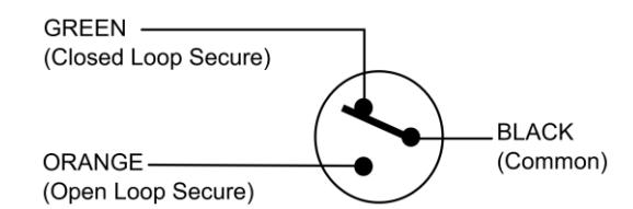
Figure 3
SWITCH INFORMATION
Voltage Rating: 120VAC/VDC Current Rating: 250Ma Power Rating: 30W max. Switch Function: SPST-NO