DynaLock ILBIN Series Installation Instructions
Open the original PDF document
View PDF

705 Emmett Street ● P.O. Box 2728 ● Bristol, CT 06011-2728 ● Phone (860)582-4761 ● Fax (860)585-0338
INSTALLATION INSTRUCTIONS INTERLOCK LOGIC BOARD (ILB)
PLEASE READ BEFORE INSTALLATION
MOUNTING THE INTERLOCK LOGIC BOARD
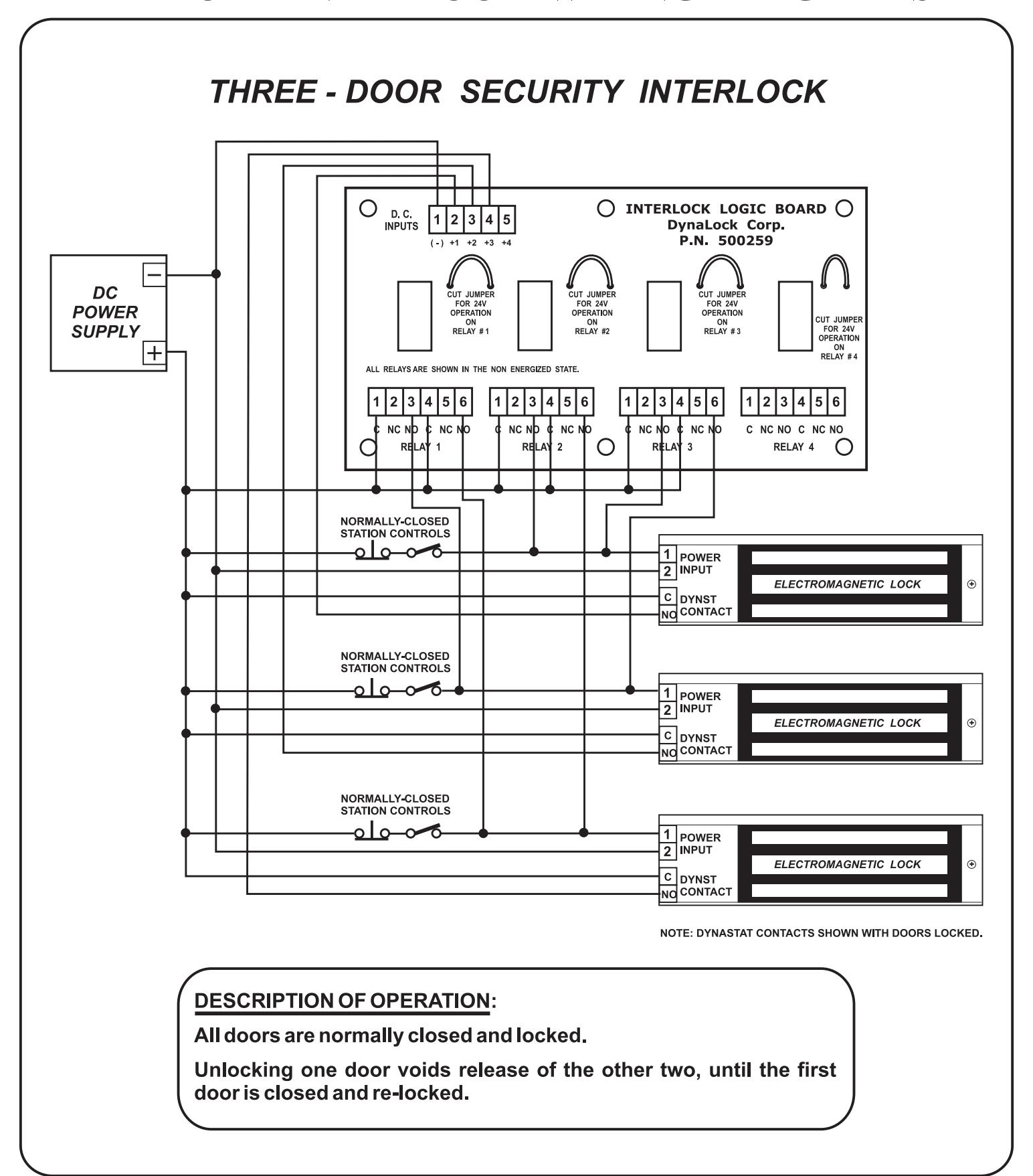
The Interlock Logic Board (ILB) can be mounted in any DynaLock Power Supply, using 6-#6-32 screws or the double-stick tape supplied.
WIRING THE INTERLOCK LOGIC BOARD
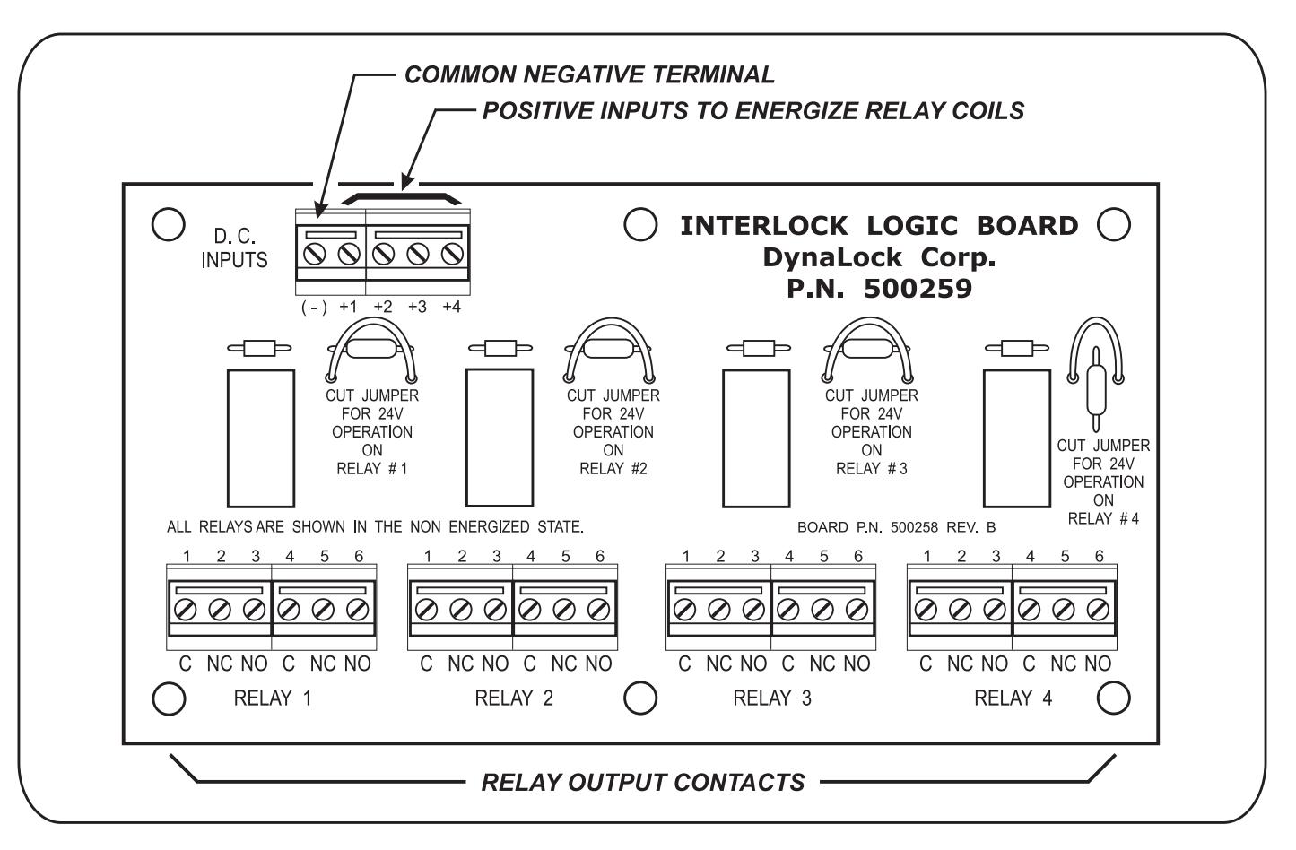
The ILB has 4 double-pole, double-throw relays that are field selectable for 12 or 24 volt DC operation. The relays are factory set for 12 VDC. To select 24 VDC operation cut the blue jumper located to the right of the relay. The relay contacts are rated 2 Amp @ 30 VDC. The current draw of each relay is 35 mA @ 12 or 24 volts.
The relay coils have a common negative input terminal. To energize individual relays apply a positive input voltage to the terminals marked +1, +2, +3 or +4.
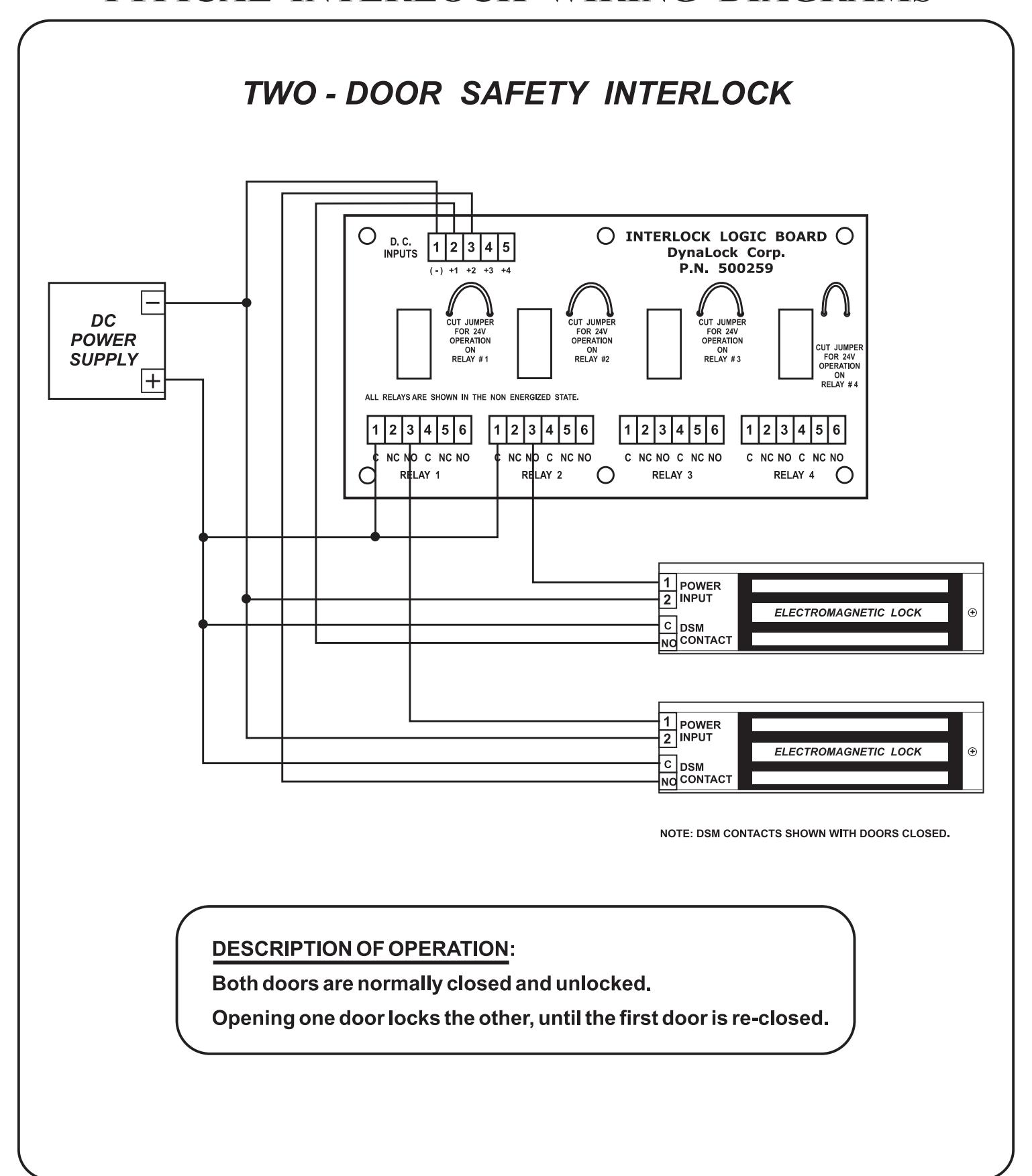
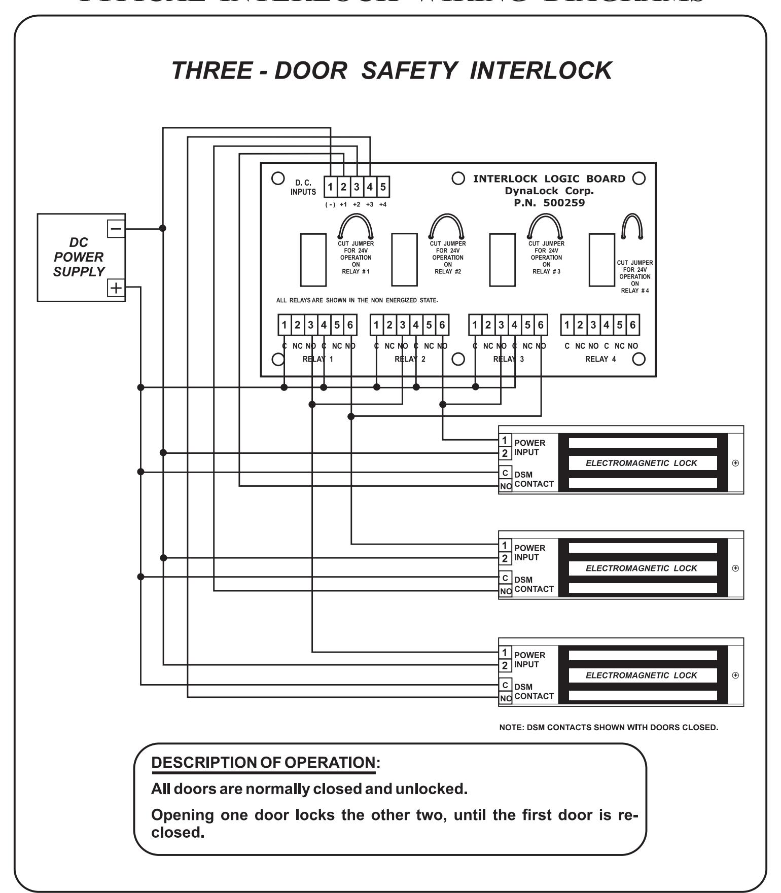
TWO - DOOR SECURITY INTERLOCK O INTERLOCK LOGIC BOARD D. C. INPUTS 1 2 3 4 5 DynaLock Corp. P.N. 500259 DC CUT JUMPER CUT JUMPER FOR 24V OPERATION FOR 24V OPERATION FOR 24V OPERATION POWER CUT JUMPER ON RELAY #2 ON RELAY #1 ON RELAY #3 SUPPLY FOR 24V OPERATION ON RELAY #4 + ALL RELAYS ARE SHOWN IN THE NON ENERGIZED STATE. 1 2 3 4 5 6 1 2 3 NC NO C NC NO C NC NO NC NO C NC NO C NC NO C NC NO C NC NO RELA RELAY RELAY 3 2 RELAY 4 NORMALLY-CLOSED STATION CONTROLS 1 POWER 2 INPUT ELECTROMAGNETIC LOCK CDYNST NO CONTACT NORMALLY-CLOSED STATION CONTROLS 1 POWER 2 INPUT ELECTROMAGNETIC LOCK • CDYNST NOTE: DYNASTAT CONTACTS SHOWN WITH DOORS LOCKED. DESCRIPTION OF OPERATION: Both doors are normally closed and locked. Unlocking one door voids release of the other, until the first door is closed and re-locked.