DynaLock GLB2 Series Installation Instructions
Open the original PDF document
View PDF

1-877-DynaLock www.dynalock.com
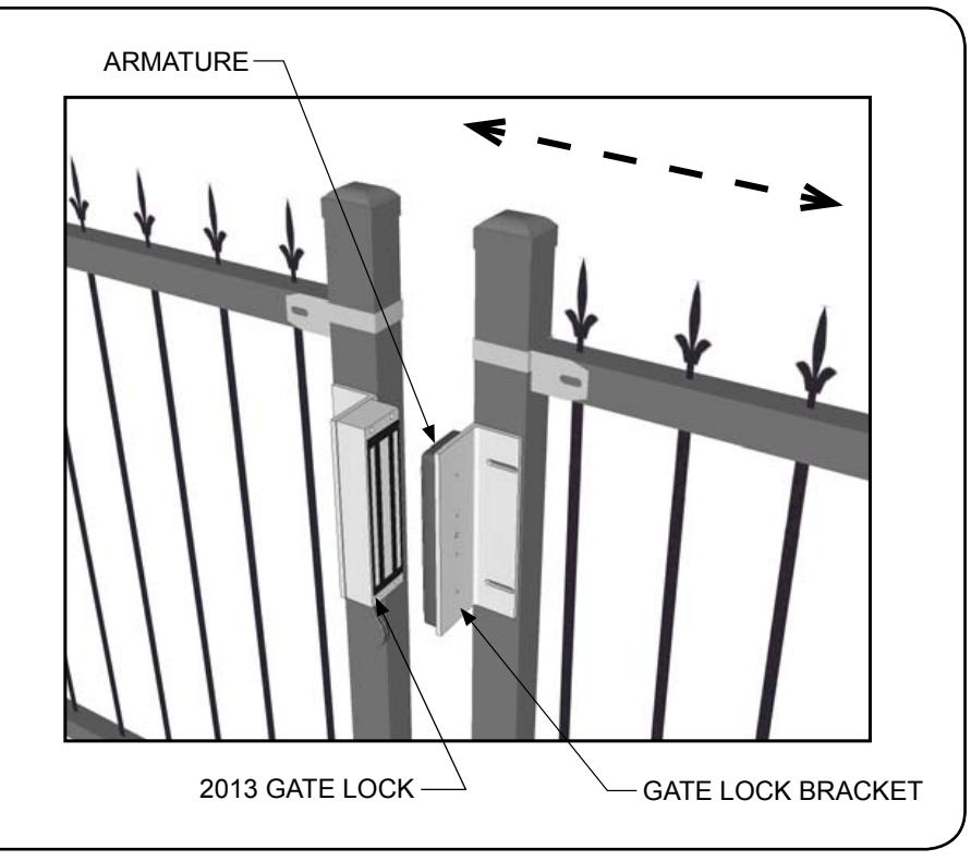
MODEL GLB2 - GATE LOCK BRACKET FOR SLIDING GATE
INSTALLATION INSTRUCTIONS
PLEASE READ BEFORE INSTALLATION
Familiarize yourself with the gate and post conditions prior to installation. This kit contains two "L" brackets and hardware to facilitate the installation of a 2013 Gate Lock on a sliding gate: one is predrilled to accept the 2013 Gate Lock and one is predrilled for the armature. Please see the 2013 Gate Lock instructions for more information.
Due to the wide diversity of gate designs, additional custom hardware or bracketry may be required to complete the installation.
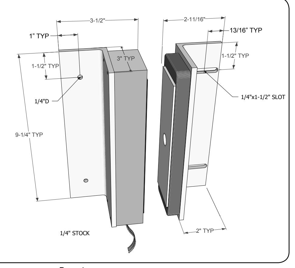
BRACKET MOUNTING
Using the brackets, along with the measurements shown, mark the hole locations on the gate/ post (see next page for how to attach the armature and lock to the brackets).
Drill and tap for 1/4-20 and secure with the (4) 1/4-20x1-1/2" machine screws included
- OR -
drill 3/16" holes and secure with the (4) #14x1-1/2" included sheet metal screws.

MODEL GLB2 - GATE LOCK BRACKET FOR SLIDING GATE INSTALLATION INSTRUCTIONS
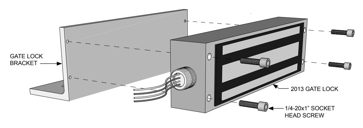
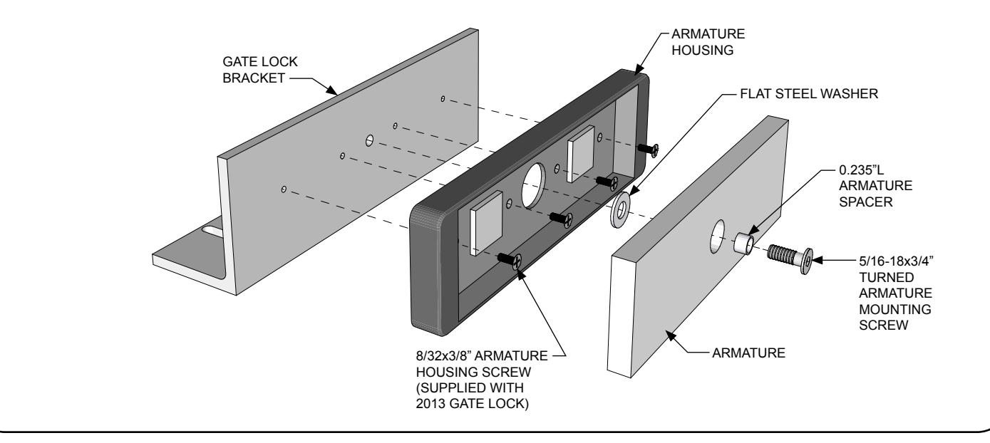
ATTACHING THE ARMATURE AND LOCK TO BRACKETS
Attach the 2013 Gate Lock to the Gate Lock Bracket using four (4) 1/4-20x1" socket head screws.
Attach the armature housing to the Gate Lock Bracket (with slotted holes) using four (4) 8-32x3/8" armature housing screws. Next, attach the armature as shown. Firmly tighten the armature mounting screw using a 3/16" hex wrench.
Failure to properly secure the armature to the bracket could result in serious injury or possible security breach.
HARDWARE PACK CONTENTS (PN 301377)
- (1) 5/16-18 x 3/4" FHS MACHINE SCREW (TURNED)
- (1) 0.375"D x 0.235"L ARMATURE SPACER
- (1) 1/4" FLAT WASHER
- (4) 1/4-20 x 1" SOCKET HEAD SCREW
- (4) 1/4-20 x 1-1/2" PHS MACHINE SCREW
- (4) #14 x 1-1/2" PHS SHEET METAL SCREW