DynaLock GLB Series Installation Instructions
Open the original PDF document
View PDF

Phone: (860) 582-4761 Fax: (860) 585-0338
MODEL #GLB GATE LOCK BRACKET INSTALLATION INSTRUCTIONS 705 Emmett Street Bristol, CT 06010
PLEASE READ BEFORE INSTALLATION
Familiarize yourself with the gate and post conditions prior to installation. The adjustable Gate Lock Bracket must be rigidly mounted to either the gate or gate post. The bracket may be used to mount either the #2013 armature or magnet assembly as dictated by the application.
Due to the wide diversity of gate designs additional custom hardware may be required to complete the installation.
Refer to separate instructions provided with the #2013 Gate Lock for further installation information.
GENERAL MOUNTING INFORMATION
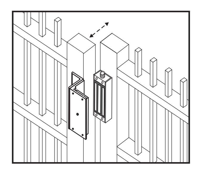
SWING GATE
Typical installation depicting the use of the Gate Lock Bracket to install the DynaLock Series 2013 Gate Lock.
The 2013 magnet assembly is mounted to the gate post. The armature is affixed to the gate using the adjustable Gate Lock Bracket.
MOUNTING PREPARATION
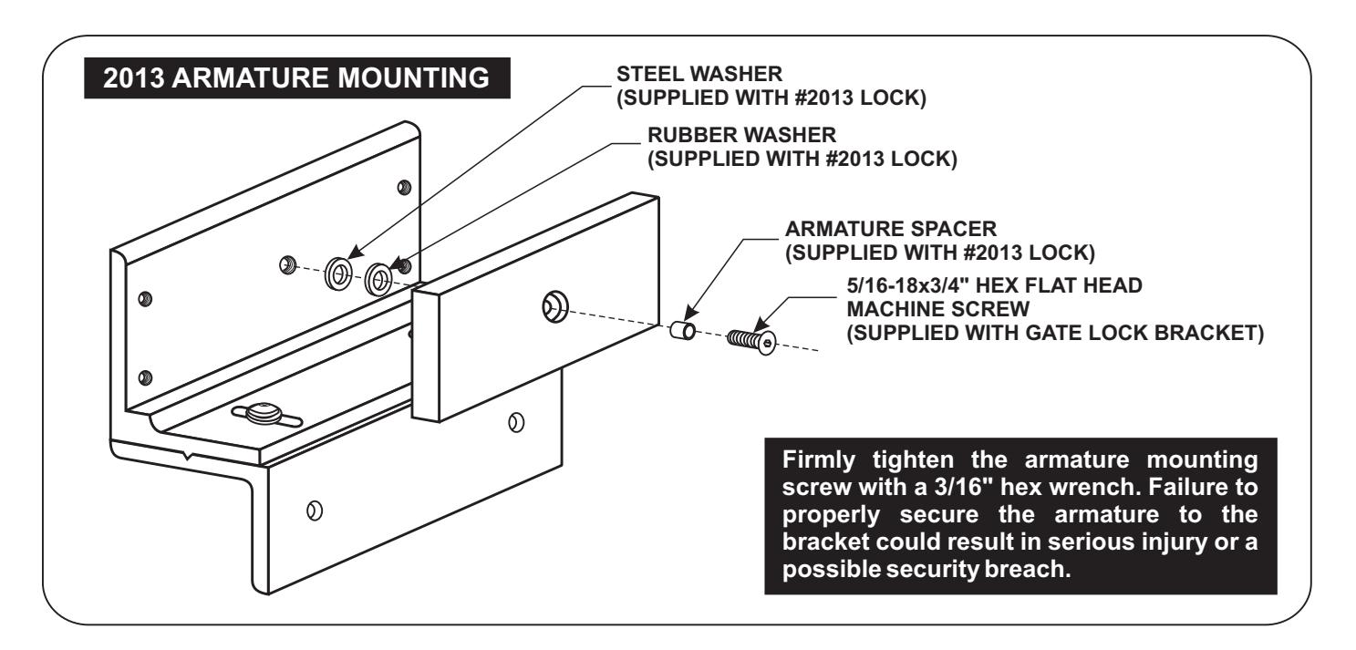
DETERMINE THE PREFFERED MOUNTING CONFIGURATION 1.
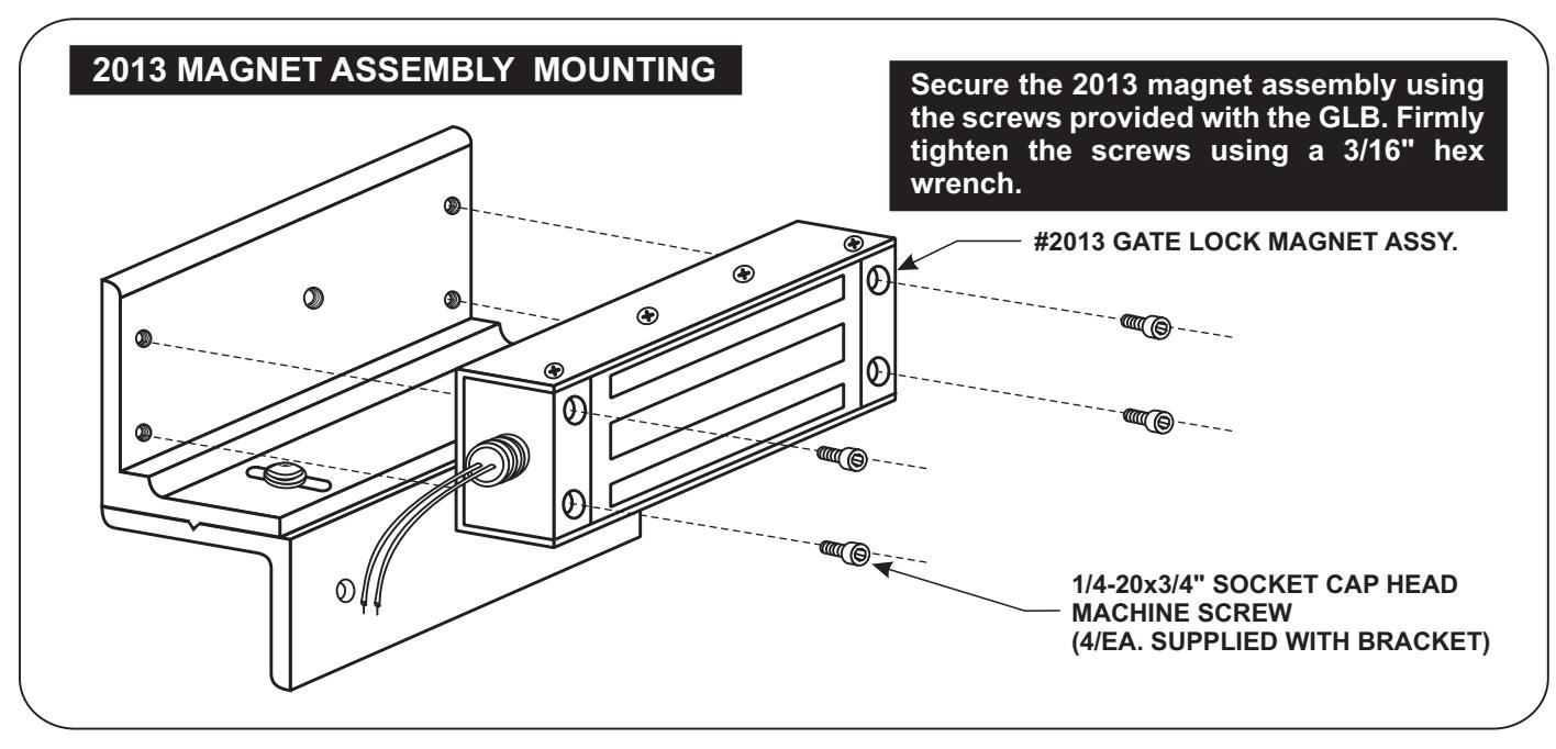
From the illustrations below determine whether the Gate Lock Bracket will be used to mount the #2013 armature or magnet assembly. Select the hardware indicated and follow the specific instructions to mount the desired component.
PREPARE THE GATE FOR MOUNTING THE BRACKET 2.
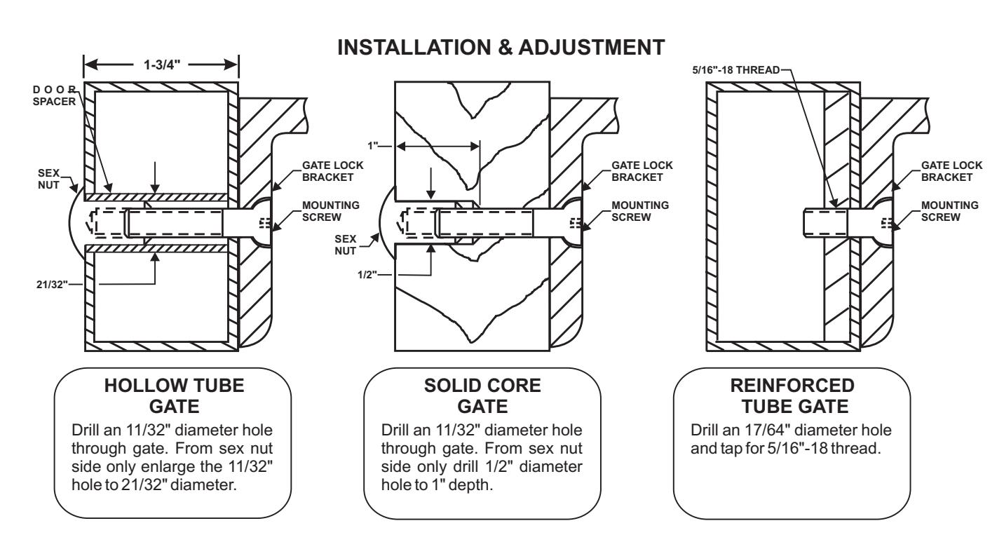
From the three illustrations on the top of page 3 select the one that resembles your gate type and follow the instructions for drilling the mounting screw holes.
Firmly tighten the mounting screws using a 3/16" hex wrench.
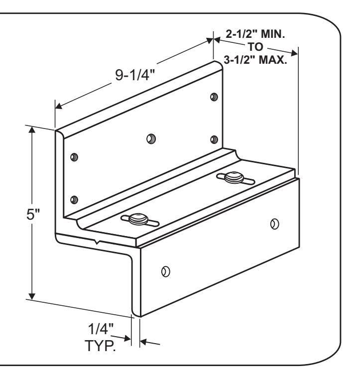
ADJUSTING THE BRACKET 3.
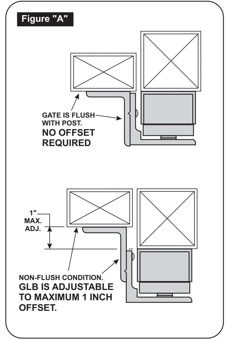
If necessary the Gate Lock Bracket may be adjusted to compensate for unusual clearance and offset conditions on the gate assembly (Refer to Figure "A").Adjust the bracket as follows:
- Using the 5/32" hex wrench provided loosen the two bracket assembly screws two (2) full turns each. a.
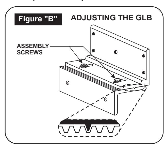
- Slide the two halves of the bracket apart as required. Align the locking rib on the bottom of the upper half with a matching groove on the lower half (Refer to Figure "B") b.
- Firmly re-tighten the assembly screws, verify proper gate and lock alignment and operation and re-adjust as necessary. c.
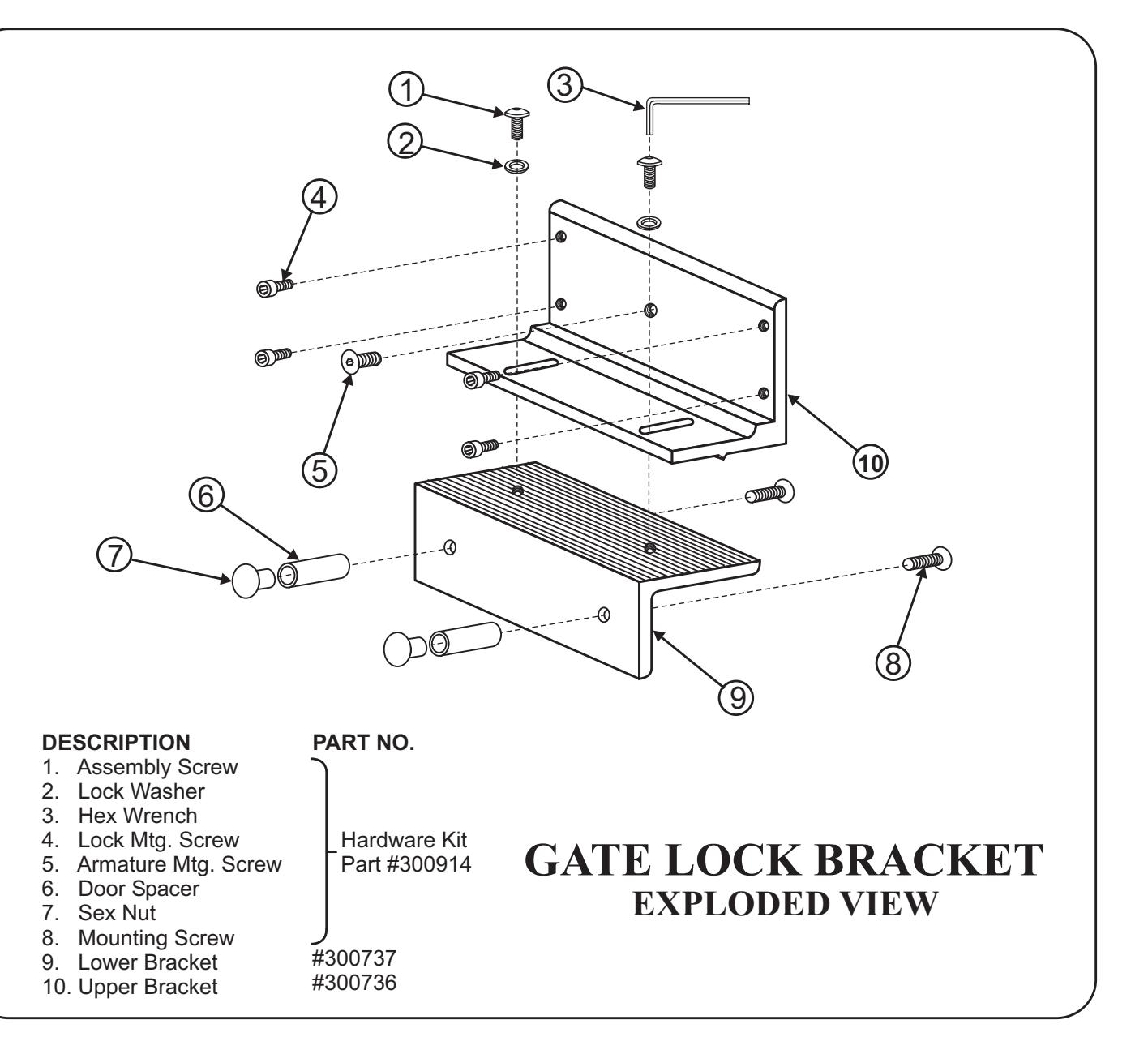
GATELOCK BRACKET BILL OF MATERIAL TOOLS REQUIRED
- 1 Mounting Instructions
- 1 Gate Lock Bracket Assembly
-
1 Hardware Kit consisting of:
- 4 1/4-20 x 3/4" socket cap head machine screws ( Gate Lock Mtg. Screws )
- 1 5/16-18 x 3/4" hex flat head machine screw ( Armature Mtg. Screw )
- 1 5/32" Hex Wrench
-
2 Mounting Bolt Assemblies, each consisting of:
- 1 5/16-18 x 1-3/4" hex flat head machine screw
- 1 5/16-18 Sex Nut
- 1 1-11/16" long Door Spacer
- 1 Electric Drill
- 1 3/16" Hex Wrench
- 1 11/32" Drill Bit
- 1 21/32" Drill Bit
- 1 1/2" Drill Bit
- 1 17/64" Drill Bit
- 1 Hammer
- 1 Center Punch
- 1 Pencil