DynaLock 8000-SF Series Installation Instructions
Open the original PDF document
View PDF

Phone: (860) 582-4761 Fax: (868) 585-0338
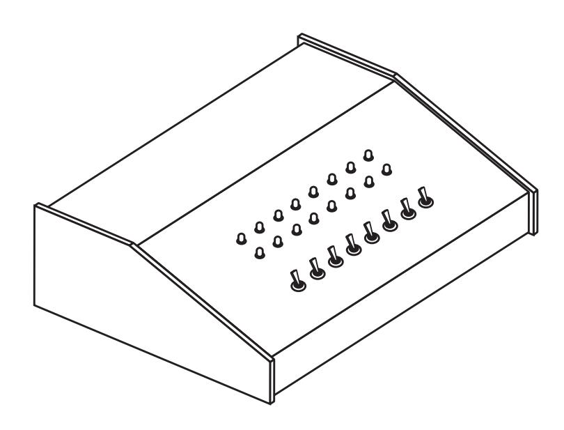
Dyna Lock MODEL #8000SF STANDARD SLOPE FRONT CONSOLE
INSTALLATION INSTRUCTIONS
PLEASE READ BEFORE INSTALLATION
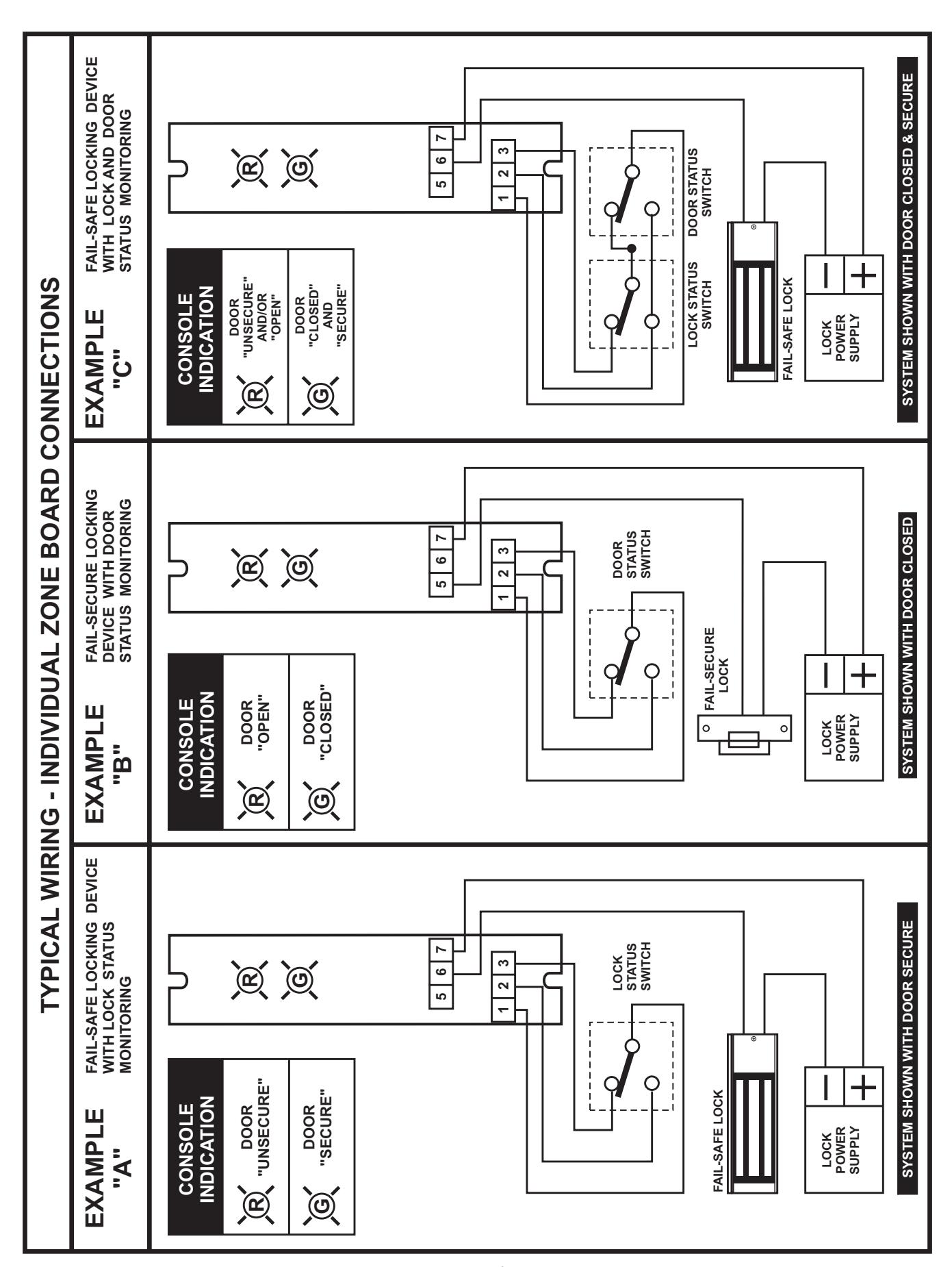
The 8000SF Series Standard Console provides remote monitoring and control capability for doors equipped with electronic security hardware. For full monitoring functions locks should be equipped with door and/or lock status signaling switches.
. The Console is designed exclusively for indoor use and thus should be protected from extremes of temperature and exposure to moisture. When necessary clean the exterior of the Console with a soft damp cloth. Do not apply any harsh chemicals or detergents directly to the Console exterior.
CONSOLE SPECIFICATIONS
POWER REQUIREMENTS: 12VDC or 24VDC models: 0.100 Amps per zone.
Two (2) LED indicators per zone - (1) Red and (1) Green MONITORING CAPABILITY:
One SPDT toggle switch per zone. CONTROL CAPABILITY:
May be either momentary or alternate-action as ordered.
Output contacts rating - 2 Amps @ 30VDC
8000SF STANDARD CONSOLE GENERAL INFORMATION
INSTALLATION INSTRUCTIONS
- Carefully remove the four (4) phillips head screws securing the Console face panel to the bottom plate. Lift the face panel off the bottom plate to expose the internal circuitry and field termination points. 1.
- Determine the entry location for the field wiring and drill the necessary access hole(s) in the Console enclosure. Be sure to thoroughly clean and remove any metal chips from the inside of the Console. 2.
- The Console will require 12 or 24VDC operating power (as ordered) fed from an external power source. To determine the proper size power supply required, multiply the number of Console zones (stations) times 0.100 Amps to calculate the total current draw. Example: Model #8008SF = 8 zones X 0.100 Amps = 0.800 Amps total current draw. 3.
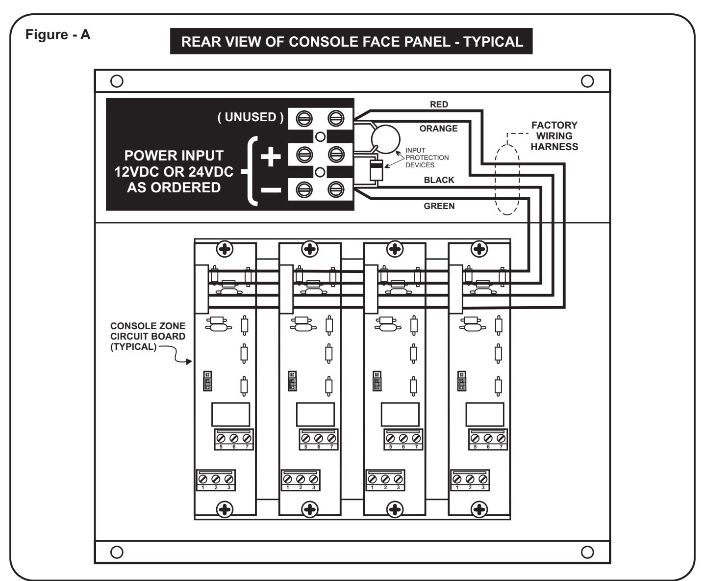
- With power "off", connect the power wiring to the Console Master Power Input terminals marked "+" and "-", as shown in Figure "A" below. Be careful to observe proper polarity when making these connections. 4.
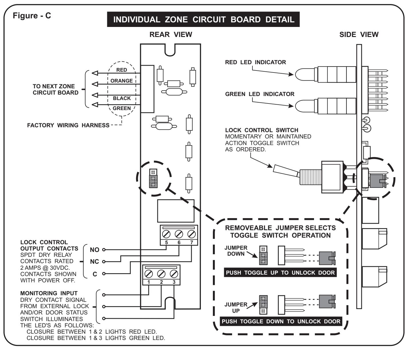
- Reference Page 4 to make the remaining connections for each individual door zone as per system requirements. The operating mode for the Lock Control Switch may be individually set on each door's zone board. Refer to Figure "C" and set the Lock Control Switch jumpers as desired. 5.
- Re-assemble the Console making sure not to damage any wiring. Where furnished, apply the optional Console Label Kit to the face panel as desired. Console installation is now complete. 6.
8000SF STANDARD CONSOLE GENERAL INFORMATION
page 4