DynaLock 7080 Series Installation Instructions
Open the original PDF document
View PDF

MODEL #7080 TIME DELAY MODULE INSTALLATION INSTRUCTIONS
The Model 7080 is a multi-purpose in-line timer designed to provide adjustable delayed-relocking of a fail-safe or fail-secure electronic lock, when coordinated with a momentary access/egress control device. The 7080 is supplied with a double-stick tape backing to allow convenient mounting at the discretion of the installer.
SPECIFICATIONS
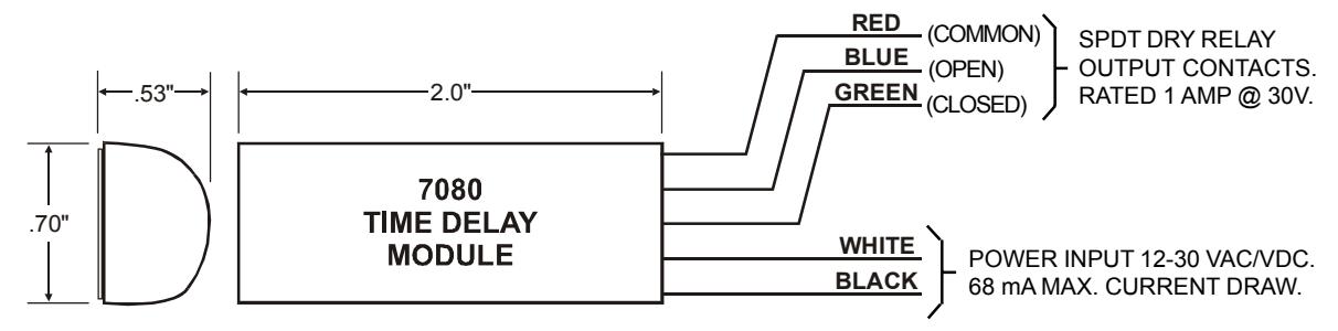
INPUT POWER: 12 - 30 VAC/VDC. NON-POLARITY SENSITIVE.
CURRENT DRAW: 25 mA MAX. DC / 68 mA MAX. AC
DIMENSIONS: 2.0" L x .70" W x .53" H
RELAY OUTPUT: SPDT DRY TIME DELAY CONTACTS. RATED 1 AMP @ 30V
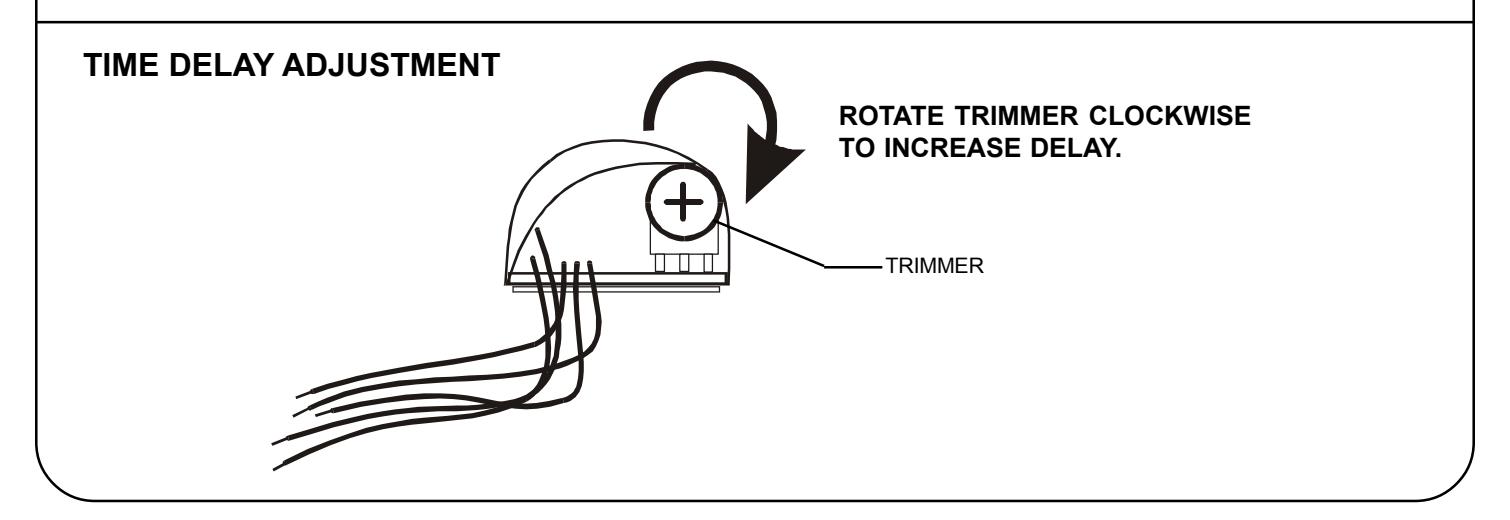
DELAY RANGE: 0 - 60 SECONDS, ADJUSTABLE.
TERMINATIONS: 4" COLOR-CODED, 20 GA. PRE-STRIPPED WIRE LEADS.
GENERAL INFORMATION
NOTE: OUTPUT CONTACTS ARE SHOWN WITH MODULE ENERGIZED. SEE PAGE 2 FOR TYPICAL SYSTEM WIRING EXAMPLES.
7080 SERIES TIME DELAY MODULE WIRING EXAMPLES
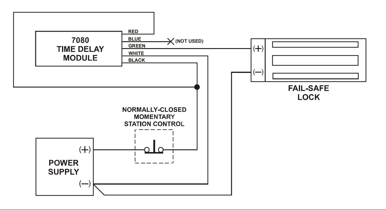
A TYPICAL WIRING - FAIL-SAFE LOCKING DEVICE
Fail-safe locking device is normally locked with power applied. Momentarily opening the normally-closed station control contact de-energizes the time delay relay. The time delay closed contacts open de-energizing the lock. Door will remain unlocked until time delay expires.
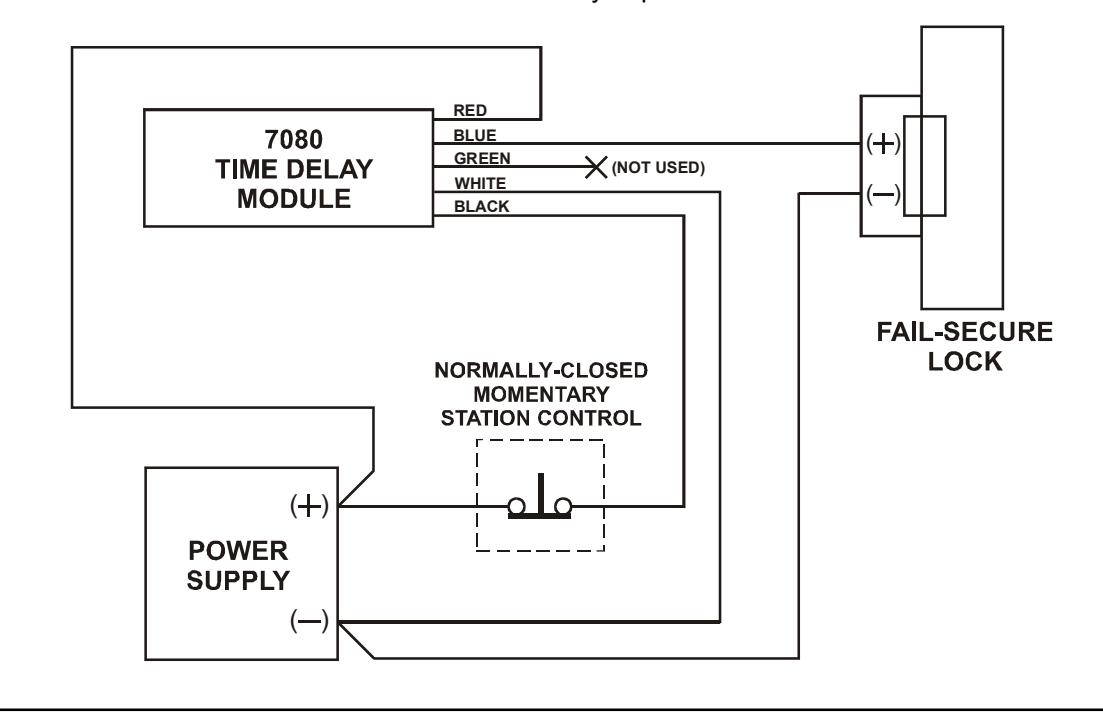
B TYPICAL WIRING - FAIL-SECURE LOCKING DEVICE
Fail-secure locking device is normally locked with no power applied. Momentarily opening the normally-closed station control contact de-energizes the time delay relay. The time delay open contacts close energizing and releasing the lock. Door will remain unlocked until time delay expires.