DynaLock 6600 Series Installation Instructions
Open the original PDF document
View PDF

6600 Series Halo-Lighted Piezo REX Pushbuttons INSTALLATION INSTRUCTIONS
1. Introduction
DynaLock 6610 and 6620 are heavy duty, illuminated, vandal resistant, analog timed switches, designed for both indoor and outdoor use.
The Piezoelectric switches generates a dry contact N.O. and N.C relay pulse simply by placing your finger on it, with no physical movement or moving parts.
The 6610 and 6620 include features such as solid state Piezoelectric Switch Technology, an adjustable output time of 1 to 60 seconds, and field selectable illumination status. This feature allows you to select from a number of vibrant color options to show relay ON or relay OFF status.
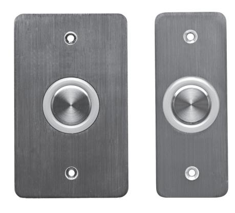
Figure 1: 6610 and 6620 Electronic Switches
2. Technical Specifications
2.1 Electrical Characteristics
Operating Voltage Range: 10 to 24 VDC
Two Outputs: 1 Normally Open (N.O), 1 Normally Closed (N.C)
Jumper Selectable Relay: (Normally ON or OFF) Input Current, Max: Maximum less than 140mA @
24VDC
Button Switch Life: 1 Billion Cycles
Relay Life Expectancy: 100,000 @ 2A 30VDC
500,000 @ 1A 30VDC
2.2 Environmental Characteristics
Operating Environment: Indoor and outdoor (meets IP-65) Operating Temperature: -35˚C to 66˚C (-31˚F to 151˚F) Operating Humidity: 0 to 85% (Non-Condensing)
2.3 Physical Characteristics
Material: Stainless steel faceplate and button cap Dimensions:
6610 : 11.4 cm x 7 cm x 3.2 cm (4 ½" x 2 ¾" x 1 1/4") 6620 : 11.4 cm x 4.4 cm x 3.2 cm (4 ½" x 1 ¾" x 1 1/4")
Weight :
6610 : 238 g (8.395 oz) 6620 : 173 g (6.102 oz)
2.4 Inlay Back
Figure 2 provides a view of the back of the inlay.
Top left : Nine jumper posts
Top right: Terminal blocks for operation voltage
(between 10 - 24 V DC)
Bottom left: Terminal block (Normally Closed, COM1) Bottom right : Terminal block (Normally Open, COM2)
Bottom center : Ground wire
Note: The Normally Closed (N.C.) and Normally Open (N.O) relays are not connected to each other. Each one can be used separately for different applications such as one controlling the operating a door lock and the other controlling operating a light fixture or machinery.
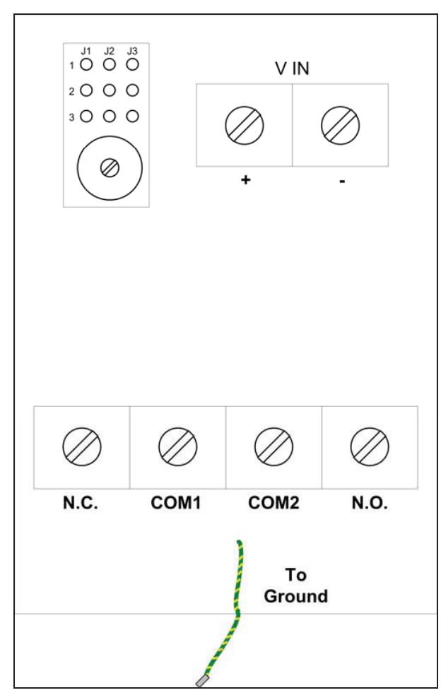
Figure 2: Inlay Back View

6600 Series Halo-Lighted Piezo REX Pushbuttons INSTALLATION INSTRUCTIONS
3. 6610/6620 General Features
The main features of the 6610 /6620 are:
- Switch Technology: Advanced Soft Touch Piezoelectric Switch
- New Weatherproof Design: Circuit assembly encapsulation
- Vandal Resistant: Stainless steel mounting plate and solid state button (Vandal was not verified by UL)
- Adjustable Output Time: The timer can be set from 1 to 60 seconds for the relay as well as the LED activation.
- Field Selectable Illumination Status: Jumper selected
- Mounting Method: Mounts directly to a single gang switchbox
- Faceplate Graphics: "EXIT", "PUSH TO EXIT" or no graphic.
4. Installation
4.1 General
The 6610 / 6620 electronic switch enables the access control of a magnetic lock or electric lock strike. Only a few steps are required to install the switch device, including:
- Selecting the physical location
- Preparing the location
- Setting the desired LED color
- Setting the mode
- Setting the timer
- Securing the protective waterproof cover
4.2 Selecting an Area for Installation
Note : The 6610/6620 switch has a face plate attached to an inlay that is imbedded in a wall with all of its wiring. You need to select the best physical location to install the 6610 /6620 .
To select a physical location:
- 1) Select a flat wall in close proximity to the door or item the switch will control.
- 2) Ensure that there are no iron beams, door frames, or other obstructions that would prevent the insertion of the inlay in the wall.
- 3) Stick the Mounting Plate provided on the wall to ensure quick and easy installation of the product.
- 4) Mark the dimensions of the inlay on the wall: 70mm x 38mm x 27mm (2.75" x 1.47" x 1.06")
4.3 Wiring Information
6610 /6620 is wired using a terminal block with binding posts. The V IN relays are located on the front upper left side of the inlay.
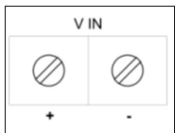
Figure 3: V IN Terminal Blocks
The N.C. output terminal block is located on the bottom left of the inlay and the N.O. output terminal block is located on the bottom right of the inlay.
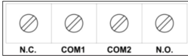
Figure 4: N.C. and N.O. Output Terminal Blocks
To wire the unit:
- 1) Open the terminal blocks using a thin Philips head screwdriver or a flat head screwdriver.
- 2) Connect the power wires to the V IN relay for operation voltage, output between 10 – 24 V DC.
- 3) Connect the N.O. and /or N.C. outputs.
Note: The Normally Closed (N.C.) and Normally Open (N.O) relays are not connected to each other. Each one can be used separately for different applications such as one operating a door lock and the other operating a light.
Note : COM1 must be connected to the adjacent N.C. relay and COM2 must be connected to the adjacent N.O. relay.
4) Connect the grounding wire to a ground.
4.4 Installing the Switch
You need to make a hole slightly larger than the inlay and install the switch.
To install the switch:
- 1) Make a hole in the wall measuring the required dimensions, adding ½ cm (1/8") on all sides in order for the gang box to slide in smoothly.
- 2) Unscrew the cover on the small box containing the jumpers and potentiometer.
- 3) Set the Jumper connections located on the upper left side of the inlay box. See Jumper Settings.
- 4) Screw the sealed cover back on the small box containing the jumpers and potentiometer.
- 5) Test the switch before screwing the inlay to the gang box.
- 6) Place the inlay with face plate in the gang box, making sure screw alignment is correct and the face plate lies flush against the wall.
- 7) Insert screws in the face plate and screw tightly to ensure a water tight seal that protects the inner wiring.

6600 Series Halo-Lighted Piezo REX Pushbuttons INSTALLATION INSTRUCTIONS
5. Jumper Settings
The 6610/6620 has 3 internal jumpers that can be connected to enable various features, including:
- Setting the LED color (Jumpers 1 and 3)
- Setting the mode and time duration of color change(Jumper 2)
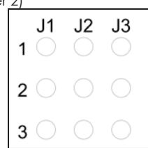
Figure 5: Jumper Posts
5.1 LED Color Feature Jumper
You can set the base color of the LED and LED color after pressing the button by inserting a jumper to activate the desired setting.
To set the LED color:
• Determine the color pattern desired and set the jumper connections accordingly.
The following table describes the LED base color before activation and after button press.
Warning : Selecting yellow is not recommended as it causes a higher electrical expectancy and may cause the unit to malfunction.
Table 1: LED Jumper Settings
| Jumper 1 | Jumper 3 | LED Color Options | ||||
|---|---|---|---|---|---|---|
| Setting | Setting | Base Color Activated Color | ||||
| *No Jumper | Connect 1-2 | OFF | GREEN | |||
| *No Jumper | Connect 2-3 | GREEN | OFF | |||
| Connect 1-2 | *No Jumper | OFF | RED | |||
| Connect 1-2 | Connect 1-2 | OFF | YELLOW | |||
| Connect 1-2 | Connect 2-3 | GREEN | RED | |||
| Connect 2-3 | *No Jumper | RED | OFF | |||
| Connect 2-3 | Connect 1-2 | RED | GREEN | |||
| Connect 2-3 | Connect 2-3 | YELLOW | OFF | |||
* Warning : When using only one jumper connection, put the second jumper connection in a safe place for future use.
5.2 Mode Feature Jumpers
You can set a timer determining how long the LED remains activated after button press or whether the LED toggles between two colors by setting Jumper 2 (J2), as follows:
Table 2: Mode Jumper Settings
| Jumper 2 (J2) set between | LED toggles between two colors | ||
|---|---|---|---|
| posts 1 and 2: | |||
| Jumper (J2) set between | The timer feature is activated | ||
| posts 2 and 3: | |||
Warning : If Jumper 2 is not set to either of these options, the switch will not work.
Toggle Feature
The toggle option allows you to toggle between two colors upon button press. The colors are determined by various jumper settings. The color remains the toggled color until the button is pressed again.
Timer Feature
When Jumper 2 (J2) is connected between posts 2 and 3, it sets the timer for the relay activation and for the LED to remain lit between 1 and 60 seconds after button press, depending on the setting. The default time is 4 seconds. The colors are determined by the various jumper settings.
The timer is a potentiometer located below the jumpers. To set the timer:
• Turn the potentiometer until the activated light stays lit for the desire amount of seconds.
Note: Turning the timer clockwise all the way sets the timer for one second. Turning the timer counterclockwise all the way sets the timer for 60 seconds.
6. Testing the Switch
After connecting the wires and setting the jumpers, test the 6610/6620 test the switch before screwing in the face plate.
To test the switch:
- 1) Press the button on the 6610/6620 .
- 2) Check to see if the electronic lock or lock strike opens and the desired light and timer settings activate.
- 3) Make sure the LED returns to its base color.
PLEASE DELIVER THIS MANUAL TO THE END USER UPON COMPLETION OF THE PUSHBUTTON INSTALLATION
FOR PRODUCT SUPPORT AND PARTS ORDERING INFORMATION CONTACT:
DynaLock Corp. 705 Emmett Street Bristol, CT 06010 Bus: (877) 396-2562 Toll-Free USA (860) 582-4761 Fax: (860) 585-0338
DYNALOCK ON THE INTERNET:
E-mail: info@dynalock.com Website: www.dynalock.com