DynaLock 6451 Series Installation Instructions
Open the original PDF document
View PDF

Phone:(860)582-4761 Fax:(860)585-0338
MODEL 6451 EXIT SENSOR BAR
INSTALLATION INSTRUCTIONS
PLEASE READ BEFORE ATTEMPTING INSTALLATIONS
DESCRIPTION OF OPERATION
The non-latching model 6451 provides immediate "no prior knowledge" egress on a door equipped with an electromagnetic lock. Depressing the bar triggers one of two internal photo-optical sensors. This in turn breaks power to a on-board control relay, which releases the electromagnetic lock.
An internal micro-switch in series with the control relay's primary normally-closed output contacts provides redundant, fail-safe lock release, should a failure of the on-board electronics occur. The 6451 requires both mechanical and electrical installation procedures described herein.
GENERAL MOUNTING INFORMATION
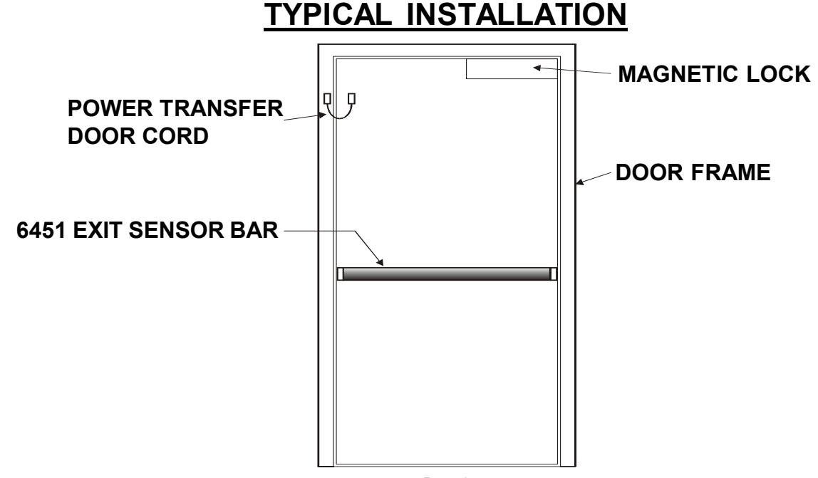
Familiarize yourself with the door conditions and the mounting instructions before you begin installation. The Exit Bar must be mounted level to function properly. A factory supplied door cord or an electric hinge may be used to transfer power from the frame to the door.
Note: This bar is not handed, simply rotate the bar to put the wiring connector at the hinge side of the door.
Note: Do not use this bar with electric deadbolt locks.
HANDLING AND MAINTENANCE
This exit bar is ruggedly constructed and designed to provide years of trouble free service.
The exit bar must be kept free of dirt, paint, or any other obstruction which may interfere with it's operation.
SPECIFICATIONS
MECHANICAL ELECTRICAL
Size: Height 2-3/8" Depth 2-7/16"
36" Door = 34" Overall bar length.
42" Door = 40" Overall bar length.
48" Door = 46" Overall bar length.
Max force to operate: 15 Lbs.
Operating Temperature Range: -10 to 120 F
Construction: Aircraft-grade aluminum.
Environmental: Weather resistant.
Finish: US28 Satin Aluminum clear anodize.
Cycles: Tested in excess of 1 million cycles.
Warranty: Life-Time
Voltage Input: 12 to 24 volts AC or DC
Current Draw: 100 ma maximum.
Output contacts: DPDT dry relay contacts. Rated
5 amps @ 30 volts.
Spike Suppression: Built-in on all inputs & outputs.
Opto/Exit Sensors: Dual, redundant.
External Connection: 8 position removable terminal
strip, 14 to 22 gauge wire.
Power Transfer Cord: 5/16 Dia. x 18" steel flex cord
with metal end blocks (less wires).

Phone:(860)582-4761 Fax:(860)585-0338
MODEL 6451 EXIT SENSOR BAR
INSTALLATION INSTRUCTIONS
| General Mounting Information | Pg. 1 |
| Handling and Maintenance | Pg. 1 |
| Description of Operation | Pg. 1 |
| Specifications | Pg. 1 |
| Exploded View | Pg. 2 |
| Typical Installation | Pg. 3 |
| Hardware Kits | Pg. 3 |
| Tools Required | Pg. 3 |
| Door Prep Drawing | Pg. 4 |
| Mounting Styles and Hardware | Pg. 5 |
| Mechanical Mounting | Pg. 6 |
| Electrical Connections and Testing | Pg. 7 |
| Trouble-Shooting | Pg. 7 |
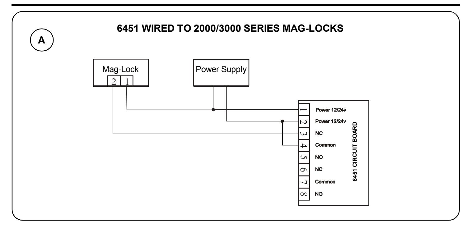
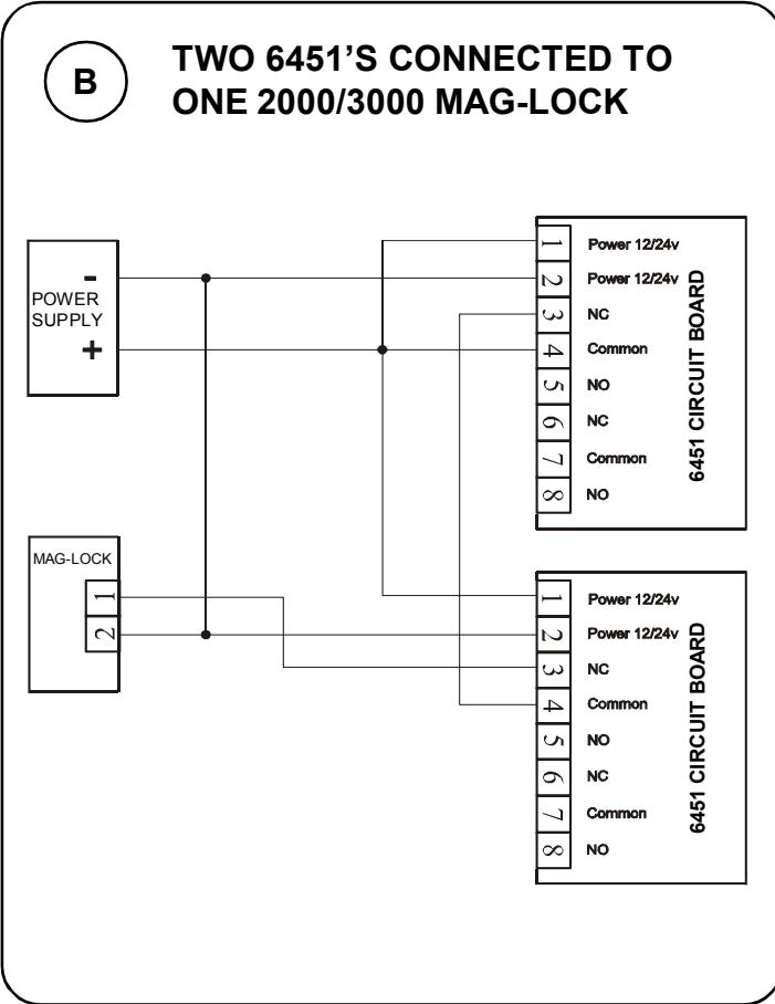
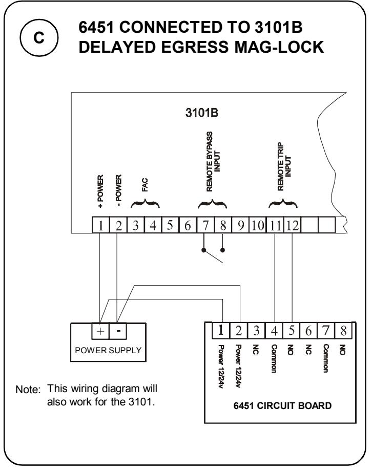
| Application Wiring Diagram | Pg. 8 |
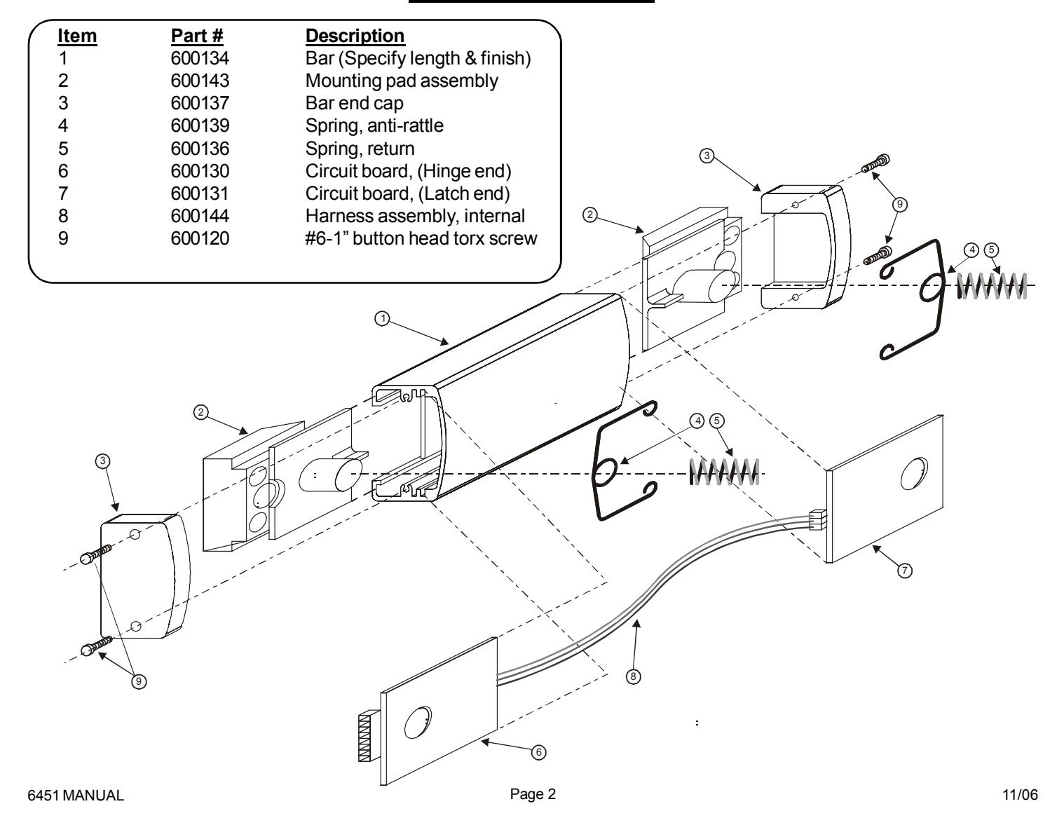
6451 EXPLODED VIEW

MODEL 6451 EXIT SENSOR BAR
705 Emmett Street Bristol, CT 06011-2728 Phone:(860)582-4761 Fax:(860)585-0338
INSTALLATION INSTRUCTIONS
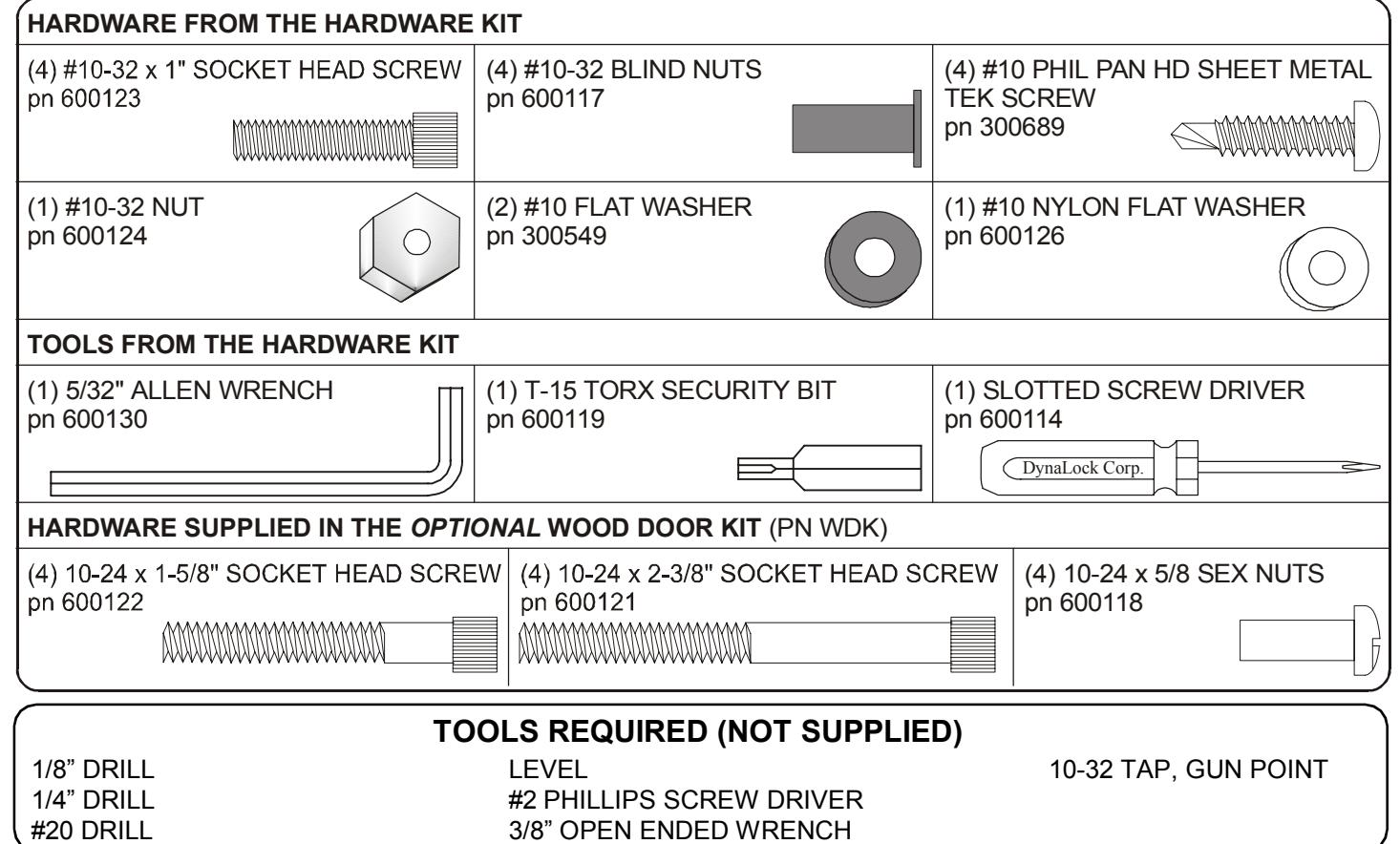
HARDWARE KIT CONTENTS & TOOLS REQUIRED
3/8" OPEN ENDED WRENCH

Phone:(860)582-4761 Fax:(860)585-0338
MODEL 6451 EXIT SENSOR BAR
INSTALLATION INSTRUCTIONS
DOOR PREPARATION DRAWING
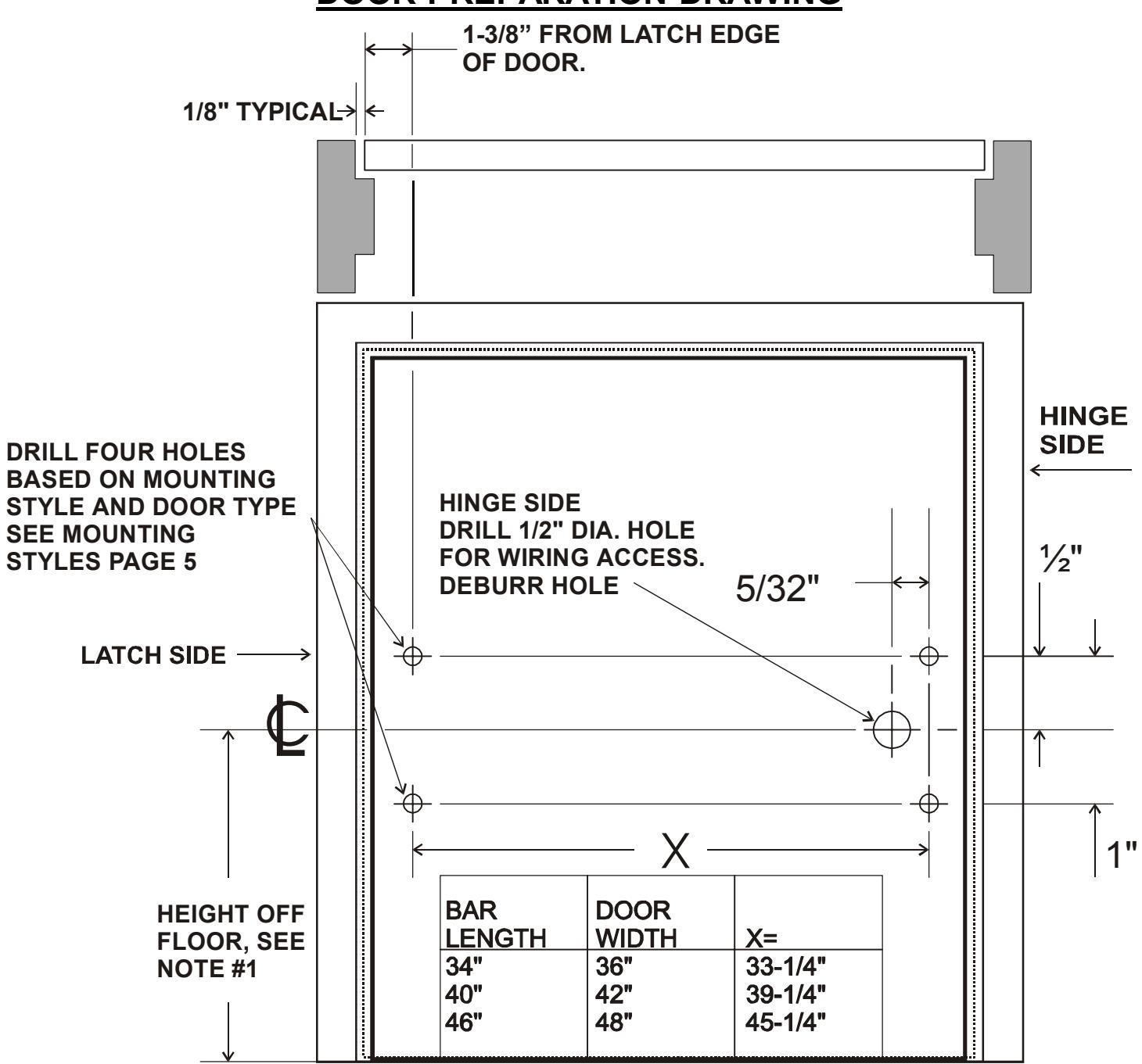
NOT TO SCALE
Note: #1
The Door and Hardware Institute recommends 42 inches.

705 Emmett Street Bristol, CT 06011-2728 Phone:(860)582-4761 Fax:(860)585-0338
MODEL 6451 EXIT SENSOR BAR
INSTALLATION INSTRUCTIONS
MOUNTING STYLES AND HARDWARE
Figure A: ALUMINUM DOOR
Use #10 TEK Screws. Drill 1/8" holes at the four mounting hole locations.
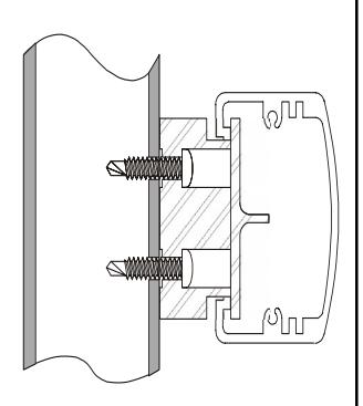
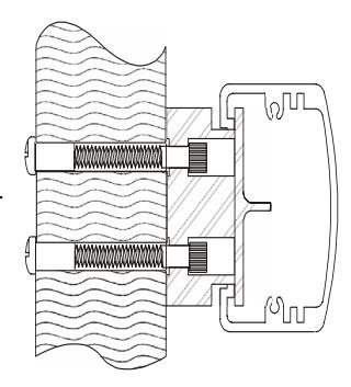
Figure B: HOLLOW METAL DOOR
Use blind nuts and #10-32 x 1" socket head screws. Drill 1/4" holes at the four mounting holes locations for the blind nuts. Refer to the "Installing Blind Nuts" on this page for more information.
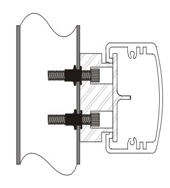
Figure C:
WOOD DOOR (Optional WDK Hardware Kit) Thru Bolt Mounting.
Use 10-24 sex nuts and 10- 24 x 1-5/8" or 2-3/8" socket head screws.
Drill 1/4" holes at the four mounting hole locations for the sex nuts and screws.
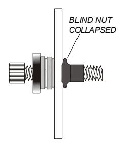
INSTALLING BLIND NUTS
Note : Blind nuts are recommended for use on steel door whose skin is too thin for a conventional sheet metal screw.
Parts from the hardware kit:
- (4) #10-32 x 1" socket head screws
- (4) # 10-32 blind nuts
- (1) #10-32 nut
- (2) #10 flat washer
- (1) #10 nylon flat washer
Tools from the hardware kit:
5/32" allen wrench
Tools required:
1/4 drill bit 3/8 open ended wrench
1. Assemble the parts as shown in Figure A .
2. Insert the assembled parts into the previously drilled 1/4" hole in the door. (Figure B ) Use the allen wrench to prevent the allen screw from rotating and to hold the parts into the door. Use the 3/8" wrench to rotate the nut clockwise.
3. Continue to tighten the nut with the wrench until the blind nut collapses as shown in Figure C . DO NOT OVER TIGHTEN!
4. Remove the screw, nut and washers from the blind nut and use them to install the remaining blind nuts, repeating steps 1 thru 4.
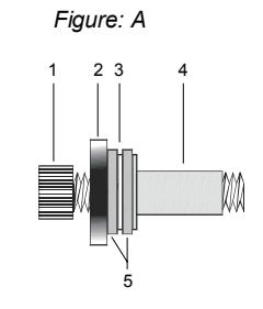
HARDWARE IDENTIFICATION
- 1- #10-32 SOCKET HEAD SCREW
- 2- #10-32 NUT
- 3- #10 NYLON FLAT WASHER
- 4- #10-32 BLIND NUT 5- #10 FLAT WASHER
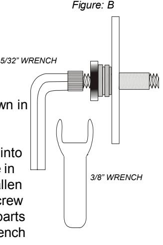
Figure: C

705 Emmett Street Bristol, CT 06011-2728 Phone:(860)582-4761 Fax:(860)585-0338
MODEL 6451 EXIT SENSOR BAR
INSTALLATION INSTRUCTIONS
MECHANICAL MOUNTING
1. Box contents, (Packing List).
- (1) 6451 Bar
- (1) Instruction manual
- (1) Hardware kit (see page 3 for details)
2. Check for proper length.
Hold the bar up to the door, you should have a minimum of 3/8" of clearance between the door stop and each end of the bar.
3. Remove the end caps.
Using the T-15 Torx security bit (supplied), remove the security screws and end caps from each end of the bar.
4. Remove the 8 position terminal connector.
This connector should be located at the hinge side of the door.
5. Determine door type, wood, hollow metal or aluminum extruded. Use the figures on page 5.
Note: Wood doors require the optional wood door hardware kit.
Hollow metal doors use 10-32 blind nuts and screws (included).
Aluminum extruded doors use #10 TEK screws (included) or the frame could be tapped for #10-32 screws.
6. Prepare the bar.
Position the mounting pads in the ends of the bar as shown in the figure on this page. The step in mounting pads may not extend beyond the end of the bar, but may sit slightly in from the end of the bar.
7. Transfer hole locations to the door.
- a. Mark a level line across the door 1" above the center line of the desired location of the bar.
- b. Hold the bar up to the door, with the top edge of the mounting pads on the level line. At the same time center the bar in the opening.
- c. Transfer the four mounting hole locations to the door. Mark center of wire access hole on hinge side of door.
- d. Drill the appropriate mounting holes for your door type.
- e. Drill a 1/2" dia hole for the wiring at the hinge end of the bar only. BE SURE TO DEBURR THE HOLE!
- f. Mount the bar using the appropriate hardware for your door type. (see page 5) Position the connector end at the hinge side of the door.
g. REMOVE THE ALIGNMENT TOOLS LOCATED AT EACH END AND DISCARD
8. Mechanical check.
Push the bar a various points along the bar, it should move freely.
9. Wiring.
- a. Run your wires thru the mounting block into the door, then thru the supplied door cord or attach to electric hinge wires (not supplied).
- b. At the hinge end of the exit bar, wire the terminal block. Refer to page 8 for proper wiring connections.
- c. Wire system components as required (see typical installation, page 3).
- d. Refer to page 8 for the operational check.
10. Re-install the end caps.
Use the supplied T-15 Torx bit.
11. Final Check.
Repeat step 8 and check that the lock unlocks each time.
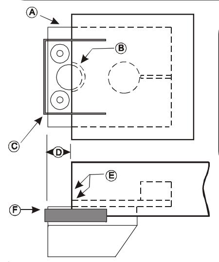
- A- Mounting Pad
- B- Wire access hole
- C- Alignment tool
- D- 1/2" Space
- E- Step and bar end to be flush

705 Emmett Street • Bristol, CT 06011-2728 Phone: (860) 582-4761 • Fax: (860) 585-0338
MODEL 6451 EXIT SENSOR BAR
INSTALLATION INSTRUCTIONS
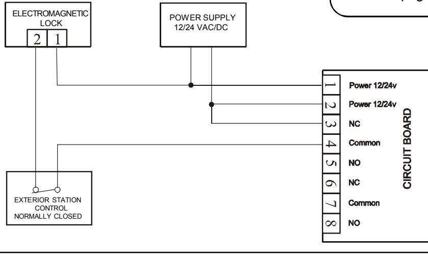
TERMINAL BLOCK DESCRIPTION
|
Terminals
1 & 2 |
Description Power input pins 1 & 2. 12 or 24 VAC/ DC @ 100ma. Note: Not polarized. |
|---|---|
|
3 - NC
4 - Common 5 - NO |
Primary relay contacts, Form C, Rated 5 amps @ 30V. Use for lock control. Redundant, internal micro-switch breaks NC output (pin 3) if relay or sensor failure occurs. |
|
6 - NC
7 - Common 8 - NO |
Second relay contact, Form C, Rated 5 amps @ 30V. Use for auxiliary functions (i.e. alarm shunting, request to exit, remote monitoring, etc.) |
OPERATIONAL TEST
- 1. When the 6451 is pushed anywhere along it's length it should move freely, without binding.
- 2. There are no adjustable parts to align inside of the bar.
- 3. When system is powered the relay will change state when the 6451 is pushed anywhere along it's length. This may be checked by using a voltmeter.
- 4. If no state change is observed when the bar is pressed, verify that there is proper voltage applied to pins 1 & 2 of the terminal block.
TYPICAL INSTALLATION
Example shown with:
- (1) Dynalock 5025 power supply
- * (1) Dynalock 7200 keypad
- (1) Dynalock 3000 series Maglock
- (1) Dynalock 6451 exit bar
*Note: This normally closed relay could also be a card reader, keyswitch device etc.
TROUBLESHOOTING
-
1. Sluggish/Binding operation of bar:
- a. Alignment tools were not removed.
- b. Mounting blocks binding, adjust blocks.
- c. Verify bar is mounted level & plumb.
-
2. Relays not opening or closing upon depressing bar.
- a. Check for proper input power.
- b. Verify wiring per diagrams on this page and page 8.
Wiring diagrams continued on following page.

Phone: (860) 582-4761 • Fax: (860) 585-0338
MODEL 6451 EXIT SENSOR BAR
INSTALLATION INSTRUCTIONS