DynaLock 6420 Series Installation Instructions
Open the original PDF document
View PDF

6420 Series Passive Infrared REX Door Sensor INSTALLATION INSTRUCTIONS
Thank you for purchasing this DynaLock passive infrared REX sensor. This sensor will provide long and dependable service when properly installed. Please read these Installation Instructions carefully, for proper and effective use.
Please Note: This device is not intended to be used as an intrusion Detection Unit. It is not a burglary-preventing device. DynaLock Corp. is not responsible for damage, injury or losses caused by accident, theft, Acts of God (including surge by lightning), abuse, misuse, abnormal usage, faulty installation or improper maintenance.
PRODUCT DESCRIPTION
DynaLock 6420 Series passive infrared "request-to-exit" sensor is specifically designed for applications involving coverage at the threshold of a doorway. A number of field selectable options and adjustments make it a compatible choice for access control applications, door strike release, alarm system shunting and automatic door operation.
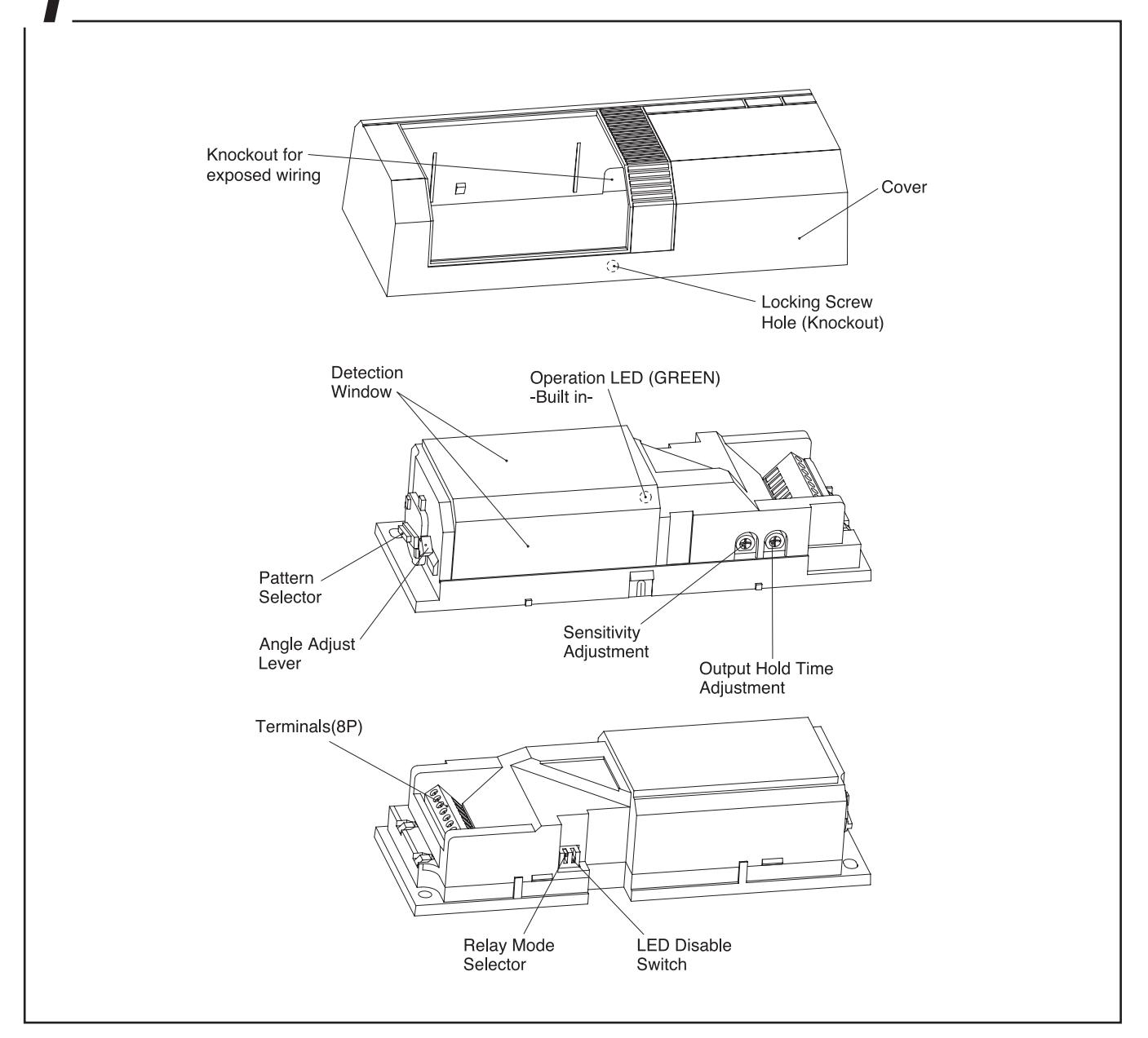
PARTS DESCRIPTION
9 DO'S AND DON'T'S
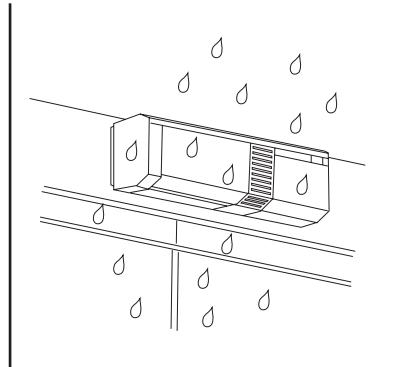
- •Do not install the unit in places where it may be affected by rain.
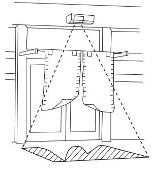
- •Do not blind the unit by placing any object in the detection area.
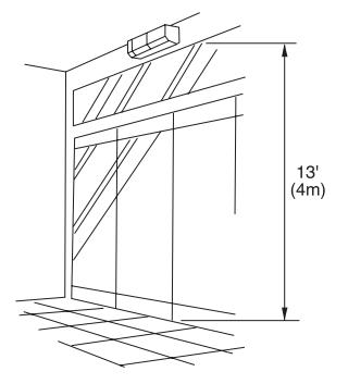
- •Keep installation height within 13' (4m).
unable to distinguish between source.
•Adjust the detection area after installation.
[MAINTENANCE]
- 1. When the unit is soiled, clean the cover with a soft cloth moistened with a small amount of cleansing-solution. Do not use chemicals such as thinners or alcohol.
- 2. Check operation once a week. Do not fail to check operation whenever furniture in coverage area is moved.
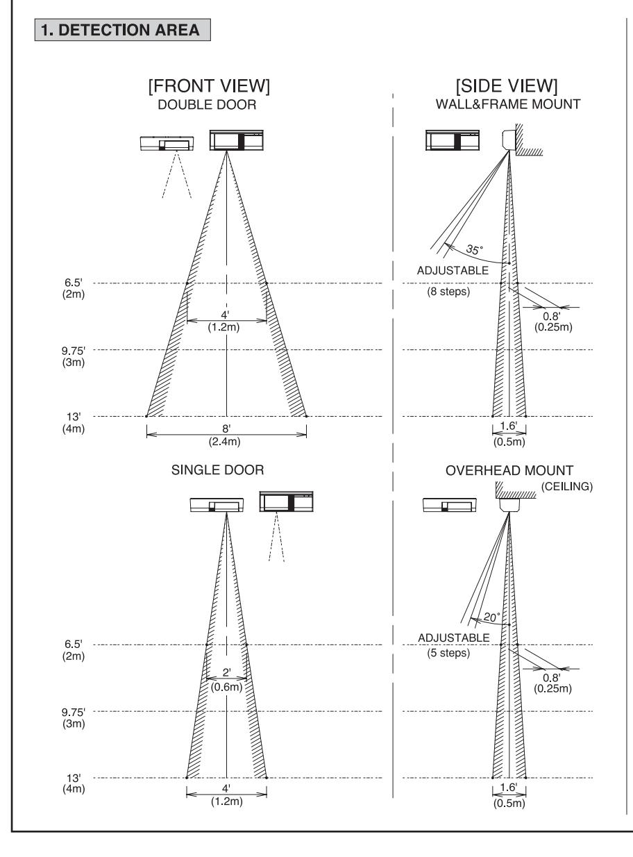
DETECTION AREA
DETECTION AREA
2. ADJUSTMENT
•The 6420 PIR is designed to detect infrared energy variations
caused by the presence of a human body. Therefore, note that similar variations in conditions in the detection area, due to
other reasons, may cause the sensor to create an output as it is
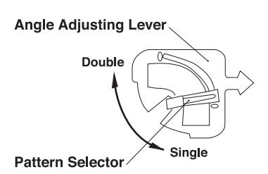
1. Set the pattern selector to double or single door by Pattern Selector.
-
2. Set the arrow of the angle adjusting lever to detection area.
- The arrow of the angle adjustment lever points to the detection area.
- 3. Walk test the unit to ensure proper detection pattern.
- Check the functioning of the unit once a week. This check should also be carried out whenever the detection area has been altered.
4 INSTALLATION
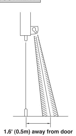
1) Select the mounting location and position of sensor (wall mount or overhead mount).

Mount the unit in the center of door.
Wall mount
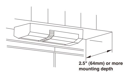
Overhead mount
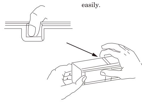
2) Separate the cover from the sensor unit.
Thumb ······ Push the window. Forefinger ···· Place finger on the knockout and pull this side to detach the cover. It will come off easily.
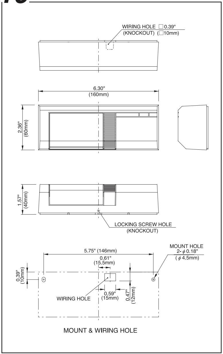
3) Drill the mounting hole.
Place the unit body on the mounting location and undermark the screw hole and wiring hole.
4) Mount the base.
Pull wires through the wiring hole and mount the unit body with the tapping screws provided.
5) Securing the cover
To lock the cover, pierce the cover locking screw hole. Insert cover locking screw and tighten. This is necessary for all UL installations.
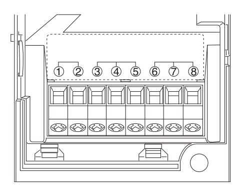
WIRING
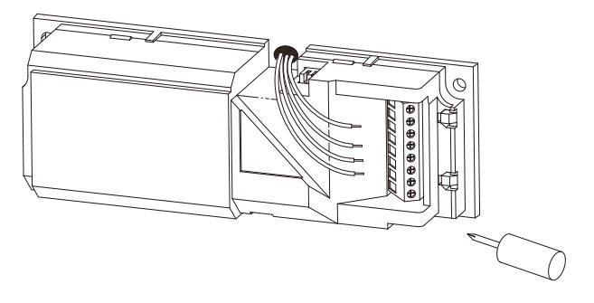
- •Run wires through the wiring ditch and insert to the wiring holes on the left side of the terminal unit.
- •Connect attached resistor in series with the power input when supply voltage is 20 to 24VAC.
- •The NC and NO output will reverse according to the "relay mode" set up. (See 6 for explanation)
- •The unit is intended to be powered by either a UL Listed power supply or a UL Listed Class 2 transformer.
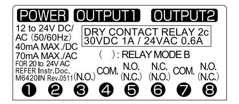
[TERMINAL ARRANGEMENT]
6 OPERATION AND FUNCTION
1) Operation
The sensor initiates two relay outputs and turns on the LED when it detects human body.
The hold time of the relay can be adjusted by the timer control
The hold time does not retrigger by detection while the relay is activated.
2) Set up
The following functions can be set up by the 2 dip switches on the side of the inner cover.
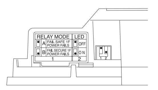
Relay mode
Relay mode can be selected by dip switch 1.
Relay mode "A"
This mode selects "FAIL SAFE" (OPENING DOOR OR UNLOCK ELECTRIC STRIKE) operation in the event of power failure.
Relay mode "B"
This mode selects "FAIL SECURE" (CLOSING DOOR OR LOCK ELECTRIC STRIKE) operation in the event of power failure.
| SET UP | RELAY MODE | CONTACT |
|---|---|---|
| 1 | Α | Fail safe if power fails (FACTORY SET) |
| 1 | В | Fail secure if power fails |
*Note that NC and NO output terminal configuration reverses according to the relay mode.
LED mode
The LED operation can be disabled by dip switch 2.
| SET UP | LED | |
|---|---|---|
| 2 | OFF | Disabled |
| 2 | ON |
Turns on during the relay
hold time. (FACTORY SET) |
3) Adjustment
The following functions can be set up by the 2 control dials on the bottom of the inner cover.
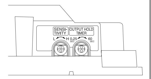
Sensitivity
The detection sensitivity can be adjusted.
Turn the dial by the sensitivity control clockwise for higher sensitivity and counterclockwise for lower setting. (FACTORY SET: MEDIAN)
Output hold time
The hold time for the 2 output relays and the LED can be adjustable between approximately and (FACTORY SET )
7 OPERATION CHECK
- (1) After wiring, set the LED to the on mode and check the operation. It takes approx. 1 minute for "warm up" after turning power on.
- (2) Confirm the detection zone by walk test.
- (3) Check the operation of the connected equipment.
- (4) If necessary, make fine adjustment.
8 TROUBLESHOOTING
Solve possible problems according to the following table. If normal operations cannot be restored by this means, contact either the dealer from whom you bought the unit or DynaLock.
| Trouble | Check | Corrective Action |
|---|---|---|
| No power supply, broken wire or improper voltage. | Correct power supply or replace broken wire. | |
| Completely inactive | Cover shielded by substances (including glass). | Remove the substances. |
| Improper area adjustment. | Readjust the protection area setting. | |
| Sometimes inactive | Improper area adjustment. | Readjust the protection area setting. |
| Cover face is soiled with dust or water drop. | Clean the cover with soft cloth. (Do not use chemicals such as thinners or alcohol.) | |
| Not yet 1 minute after power turned on | Allow for warming up time (about 1 min.) | |
| Activated when no person has passed | Unstable power voltage. | Stabilize the power voltage. |
| Something moving in protected area or too rapid temperature variations. | Remove the cause. | |
| Large electrical noise source such as power machine nearby or its wiring close to that of sensor. | Relocate device. | |
| Intense reflection of sun light or head light shining on the sensor. | Relocate device. Shield with a blind. | |
| Is the sensor reacting to passersby outside ? | Readjust the protection area. | |
| The alarm LED lights, | Poor contact output connection or broken wire or short circuit. | Check the wiring or connection. |
| but connected units are inactive | Contact output is not working. | Check the contact output terminal using a tester. |
| are mactive | Is the connected unit operation normal ? | Check the connected unit. |
9 SPECIFICATION
| PRODUCT NAME | REX SENSOR (REQUEST TO EXIT SENSOR) | ||
|---|---|---|---|
| MODEL | 6420 | ||
| DETECTION SYSTEM | Passive infrared | ||
| MOUNTING HEIGHT | 13' (4m) Max | ||
| DETECTION AREA | PATTERN | ||
|
ADJUSTMENT
RANGE |
Wall mount : Vertically
(8 steps)
Overhead mount : Vertically (5 steps) |
||
| SENSITIVITY | Adjustable | ||
| POWER SUPPLY |
12 to 24VDC (Non polarity)
or 12 to 24VAC (50Hz / 60Hz) (UL Listed Class 2) (When operated at AC20 to 24V, connect attached resistor. |
||
| POWER CONSUMPTION | 40mA or less / DC 70mA or less / AC | ||
| ОИТРИТ | Dry contact relay 2C Operation: One shot Hold time: Adjustable approx. 0.25sec. to 60sec. Contact capacity: 30VDC 1A or less / 24VAC 0.6A or less (Class 2 Power Limited) *Selectable relay operation | ||
| LED |
Green
Operation : synchronous dry contact relay (LED disabled) |
||
| WIRING CONNECTION | Terminals | ||
| AMBIENT TEN | IP. RANGE | F to F C to C) without condensation | |
| MOUNTING POSITION | Wall, ceiling, on or under frame (indoor) | ||
| WEIGHT | 5.95 oz (170g) | ||
| APPEARANCE |
COVER
(ABS RESIN) |
White | |
|
WINDOW
(PE RESIN) |
White | ||
| ACCESSORIES | ■ Tapping screw : 2 pcs. ■ Resistor (82 Ω, 3W) : 1 piece (connect when operated at AC20 to 24V) ■ Cover locking screw : 1 piece | ||
The specifications are subject to change without notice.
10 EXTERNAL DIMENSIONS

CAUTION
*Follow the voltage of the indicated power supply and wiring instruction. Incorrect voltage and wiring may cause fire, electric shock etc.

*Do not connect equipment that exceed the indicated output capacity. It may cause fire.

*Do not decompose, modify this product. It may cause fire, electric shock etc.

This Page Intentionally Left Blank
PLEASE DELIVER THIS MANUAL TO THE END USER UPON COMPLETION OF THE PIR INSTALLATION
FOR PRODUCT SUPPORT AND PARTS ORDERING INFORMATION CONTACT:
DynaLock Corp. 705 Emmett Street Bristol, CT 06010 Bus: (877) 396-2562 Toll-Free USA (860) 582-4761 Fax: (860) 585-0338
DYNALOCK ON THE INTERNET:
E-mail: info@dynalock.com Website: www.dynalock.com