DynaLock 6350 Series Installation Instructions
Open the original PDF document
View PDF

705 Emmett Street Bristol, CT 06011-2728 Phone: (860) 582-4761 Fax: (860) 585-0338
MODEL #6350 FOUR ZONE MONITOR STATION
For Delayed Egress Systems INSTALLATION INSTRUCTIONS
6350 THEORY OF OPERATION
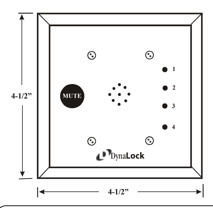
The 6350 is designed to monitor up to four 3101 or 3101B Delayed Egress Systems. The 6350 is mounted on a standard 2 gang plate and includes four bi-color LEDS, an audible and a mute switch. The 6350 allows the ability to visually and audibly monitor the 3101's from a remote location.
Note : Use of the 6350 requires each 3101 or 3101B being monitored to have the Dynastat Option (Bond Sensor).
GENERAL MOUNTING INFORMATION
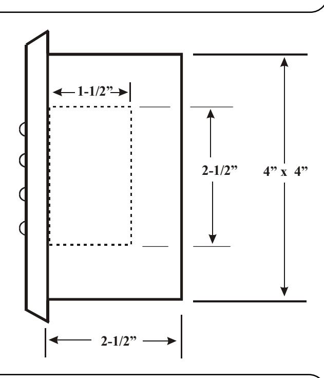
- Disassemble the 6350 by removing the four anti-tamper screws securing the cover plate to the back plate. Disassemble the panel assembly, mount the double gang box in the desired location with the desired knock-outs removed.
- 2. Bring the signal and power wires into the box leaving enough slack to attach the ends to the
- 3. Connect the signal and power wires referring to the wiring diagrams on the following pages.
- 4. Mount the panel to the box with the four #6-1" screws, then replace the cover plate with the four #6-1/4" anti-tamper screws removed in step one.
BOX CONTENTS
1 - PLUG-IN TRANSFORMER P/N 5312
1 - 6350 MONITOR ASSEMBLY P/N 600222
1 - HARDWARE PAKAGE P/N 600221
1 - INSTALLATION MANUAL
SPECIFICATIONS
SUPPLIED 12 VAC TRANSFORMER:
- INPUT POWER - 120VAC 60HZ .33AMP
- OUTPUT POWER - 12VAC 40VA
6350 PC BOARD INPUT:
- 12VAC OR 12 VDC, .42ma
MAINTENANCE
The 6350 may be periodically cleaned with a mild detergent and a clean soft cloth. To avoid damage do not use any abrasives or cleaners.
FUNCTION CHART
| CONDITION | LED | AUDIBLE |
|---|---|---|
|
NORMAL
(DOOR CLOSED) |
GREEN | OFF |
|
DURING 15 SECOND
DELAY EGRESS ATTAMPT |
YELLOW | ON |
|
DOOR OPEN
AFTER DELAY EGRESS |
RED | ON |
| DURING BYPASS | RED | ON |
|
DURING FIRE
ALARM |
RED | ON |
- The mute switch silences the current alarm only. The next alarm to occur will sound the audible again. 1.
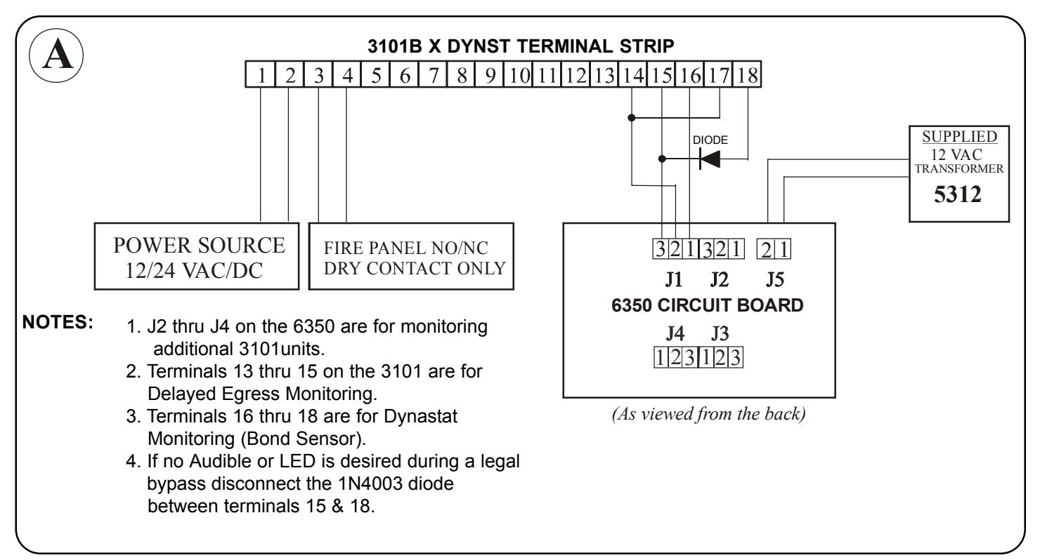
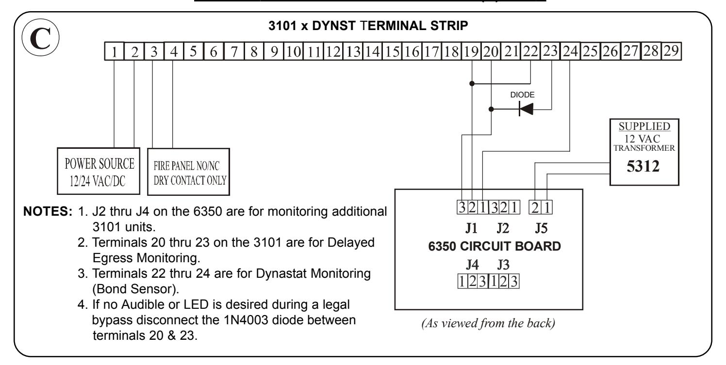
- If no audible is desired during a legal bypass disconnect the 1N4003 diode between terminals 20 & 23 on the 3101 or terminals 15 & 18 on the 3101B. The corresponding LED will be in an off state during a legal bypass when the diode is removed. 2.
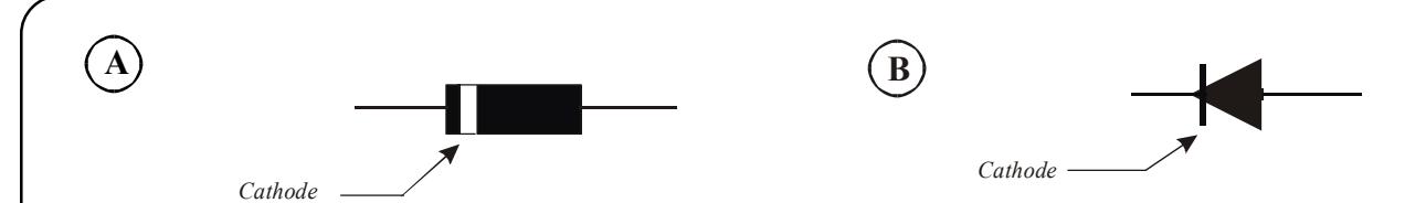
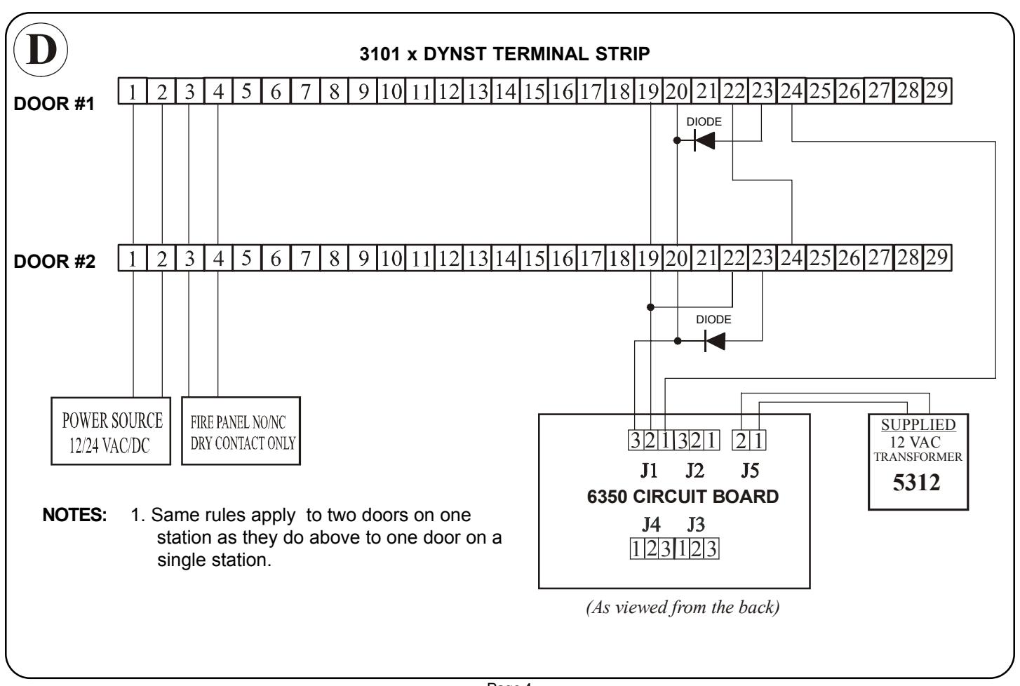
1N4003 DIODE SHOWING CATHODE SIDE Figure (A). DIODE SHOWING CATHODE SIDE IN WIRING DIAGRAM FIGURE (B). See wiring diagrams A through D for addition of diodes.
TYPICAL WIRING - 3101B SERIES LOCK(S) ONLY
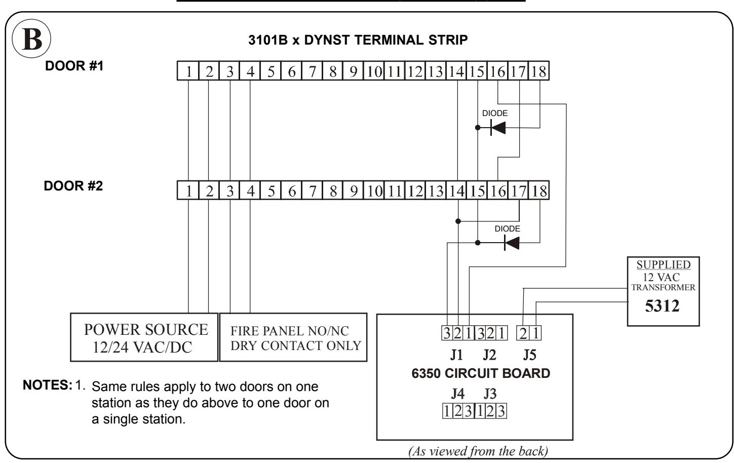
WIRING FOR TWO 3101B'S TO ONE STATION
TYPICAL WIRING - 3101 SERIES LOCK(S) ONLY
WIRING FOR TWO 3101'S TO ONE STATION