DynaLock 5600 Series Installation Instructions
Open the original PDF document
View PDF

705 Emmett Street Bristol, CT 06011-2728 Phone:(860) 582-4761 • Fax:(860) 585-0338
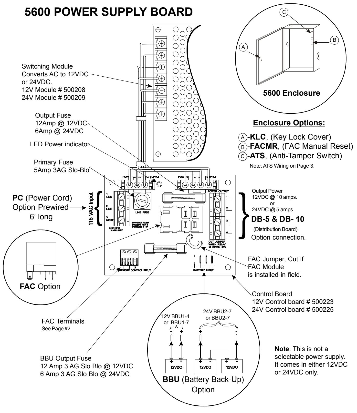
MODEL #5600 POWER SUPPLY
INSTALLATION INSTRUCTIONS
5600 Manual 03/03

Phone:(860) 582-4761 Fax:(860) 585-0338
MODEL #5600 POWER SUPPLY
INSTALLATION INSTRUCTIONS
FAC Option (Fire Alarm Control)
Kills all voltage outputs when interfaced with emergency system dry contact.
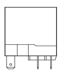
12V FAC module #500253 24V FAC module #500254
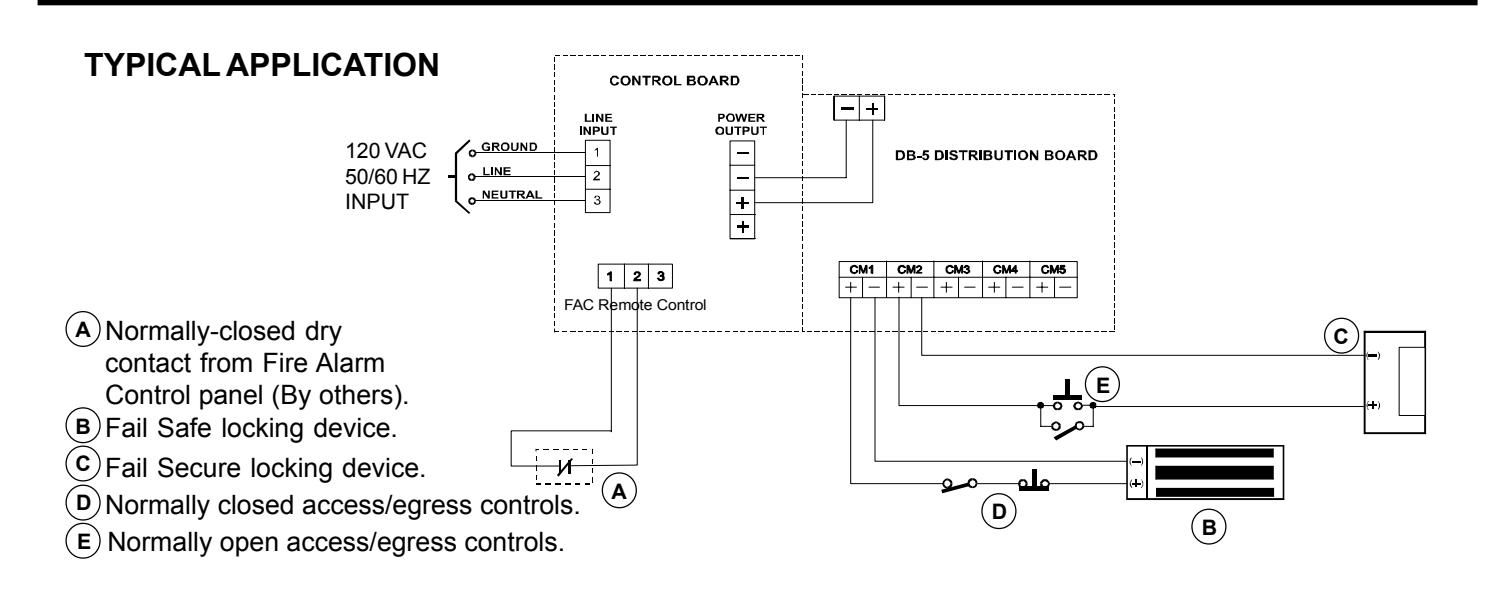
Typical Application
Normally-Closed Dry Contact from Fire Alarm Control Panel (By others). Cut Main Board Jumper when field installed. Refer to Page #1 (FAC Jumper).
Connector for
FACMR Option (FAC Manaul Reset)
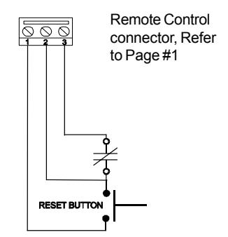
Opening normally closed contact removes all output power until the normally open reset button is momentarily pressed.
DB-5 & DB-10 Option (Distribution Board)
Two size distribution boards (5 or 10 position) are available to provide individually fused output terminals for each lock zone.
*Resettable Fuse Supply Main Board
*Resetting is done by first correcting the overload then disconnecting the load or turning off the line voltage for two minutes.
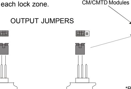
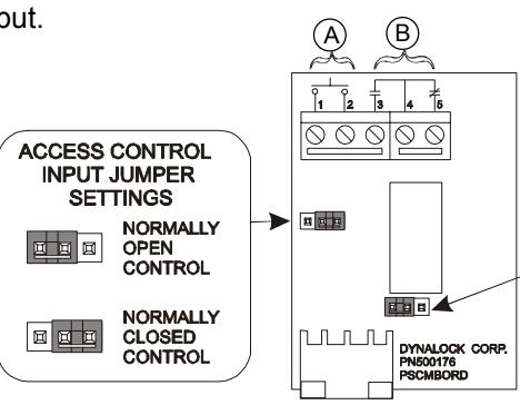
CM Option (Control Module)
(Factory Setting)
Accepts access/egress control dry contact input. Provides SPDT relay output.
Without Control Module Option With Control Module
Access Control Input, Dry Contacts Only. A
DC Input from Power

POWER SUPPLY 705 Emmett Street Bristol, CT 06011-2728 Phone: (860) 582-4761 • Fax: (860) 585-0338
INSTALLATION INSTRUCTIONS
MODEL #5600
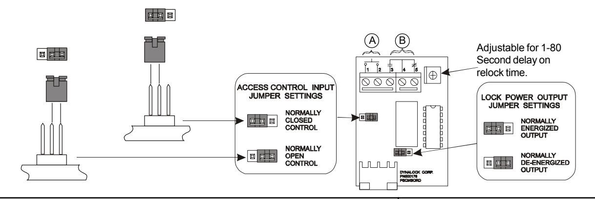
CMTD Option (Control Module with Time Delay)
Same as CM Option with Relock Time Delay
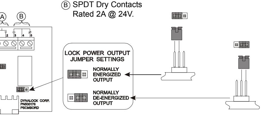
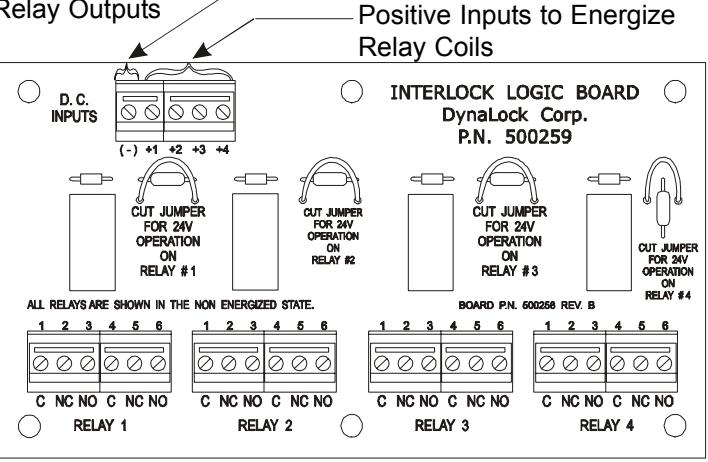
- (A) Access Control Input, Dry Contacts Only.
- (B) SPDT Dry Contacts Rated 2A @ 24V.

Note: Separate ILB user manual shows typical wiring diagrams.
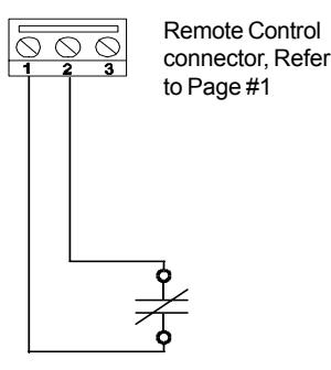
ATS Option
(Anti-Tamper Switch)
Contact held open with Enclosure cover closed.

Contact closed with Enclosure cover open.

NOTE: ATS switch contacts rated .25A @ 24V.
Installation Information
LOCK CAPACITY CHART
|
Single Full
Size |
Double Full
Size |
Single | Double |
Single Delay
Egress |
Deadbolt | |
|---|---|---|---|---|---|---|
| 12VDC | 18 | 9 | 18 | 9 | 11 | 10 |
| 24VDC | 18 | 9 | 18 | 9 | 8 | 9 |
CURRENT DRAW UP TO 1/2 AMP
| Voltage | 20 AWG | 18 AWG | 16 AWG | 14 AWG | 12 AWG | 10 AWG |
|---|---|---|---|---|---|---|
| 12VDC | 50Ft. | 100Ft. | 150Ft. | 250Ft. | 400Ft. | 625Ft. |
| 24VDC | 150Ft. | 225Ft. | 350Ft. | 550Ft. | 900Ft. | 1375Ft. |
* This chart indicatess minimum recommended wire size, but local codes prevail

705 Emmett Street Bristol, CT 06011-2728 Phone:(860) 582-4761 Fax:(860) 585-0338
MODEL #5600 POWER SUPPLY
INSTALLATION INSTRUCTIONS
TROUBLESHOOTING
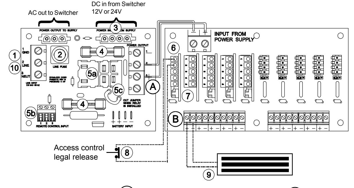
- 1 Check input line power.
- 2 Check line fuse.
- Check For 12 or 24 VDC from 3
- Switcher. 4
- Check F2 & F3 output fuses. Check that FAC Module is properly 5a
- seated. (If applicable) Terminals 1 & 2 must be jumpered if 5b
- unit has FAC Module. 5c
Note: Start at ' No Output Power @ A
A B
- Check jumper settings on CM/CMTD module(If applicable). 6
- Check jumper setting on DB-5/DB-10 card. 7
- Check for proper access switch contact status. 8
- Check load & external wiring for short condition. 9
- Reset Power Supply (With no load) by disconnecting input power at for 2 minutes. 1 10
5600 Manual 03/03 Page #4
No Output Power @ No Output @