DynaLock 5500 Series Installation Instructions
Open the original PDF document
View PDF

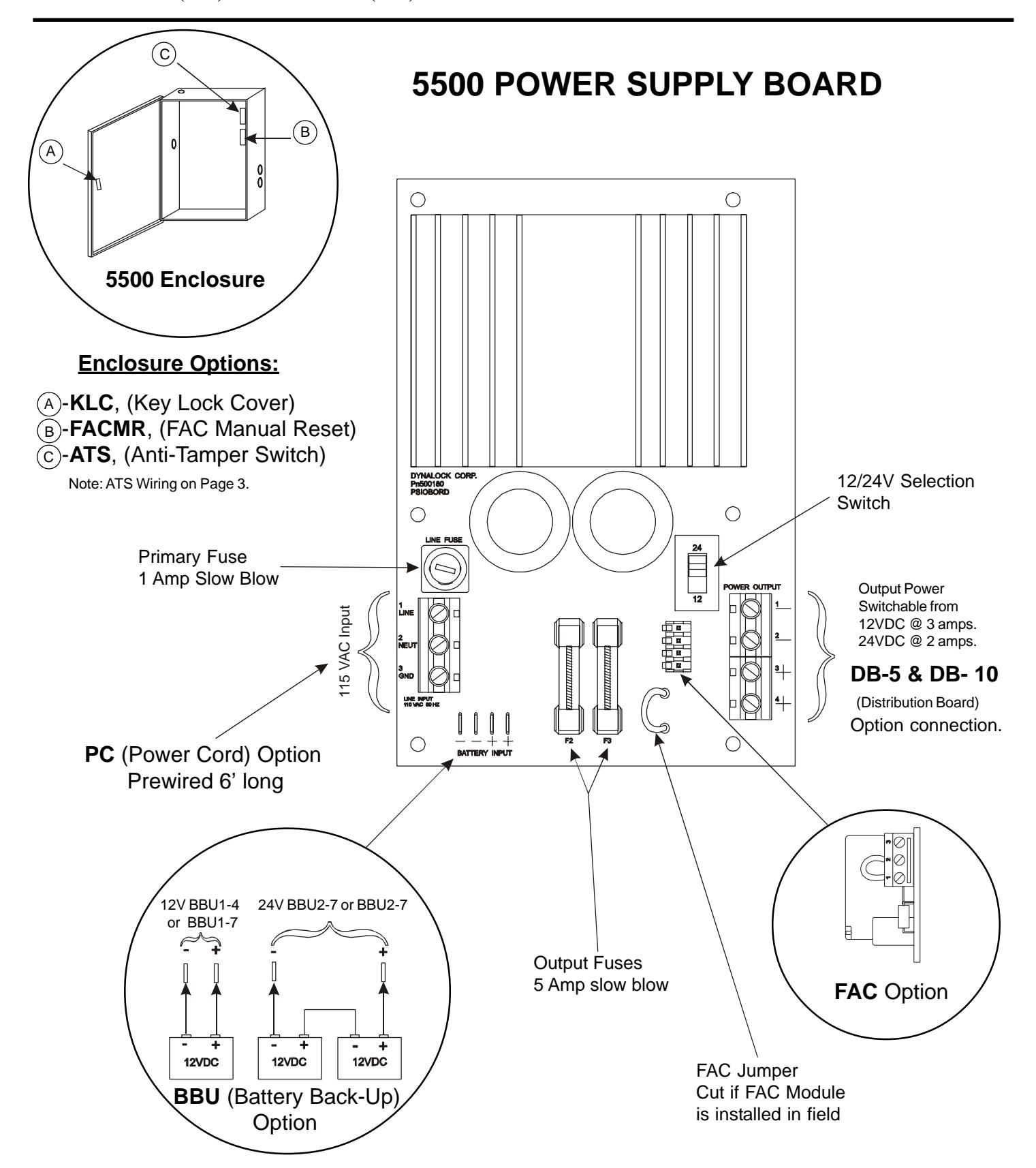
MODEL #5500 POWER SUPPLY
INSTALLATION INSTRUCTIONS

MODEL #5500 POWER SUPPLY
INSTALLATION INSTRUCTIONS
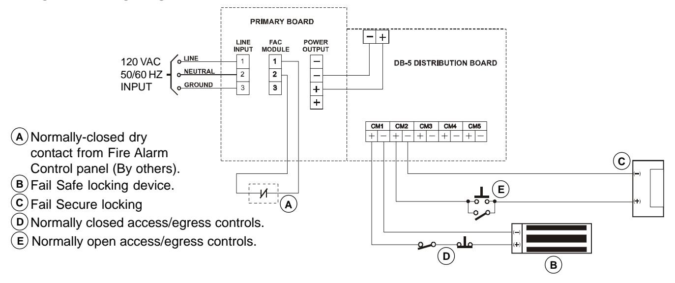
FAC Option (Fire Alarm Control)
Kills all voltage outputs when interfaced with emergency system dry contact.
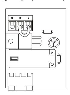
Module supplied with jumper on terminals 1 & 2 as shown.
Typical Application
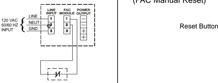
Normally-Closed Dry Contact from Fire Alarm Control Panel (By others). Cut Main Board Jumper when field installed. Refer to Page #1 (FAC Jumper).
FACMR Option
(FAC Manual Reset)
Opening normally closed contact removes all output power until the normally open reset button is momentarily pressed.
DB-5 & DB-10 Option (Distribution Board) Two size distribution boards (5 or 10 position)
are available to provide individually fused output terminals for each lock zone.
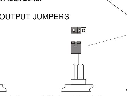
Connector for
CM/CMTD Modules
DC Input from Power Supply Main Board
*Resettable Fuse
*Resetting is done by first correcting the overload then disconnecting the load or turning off the line voltage for two minutes.
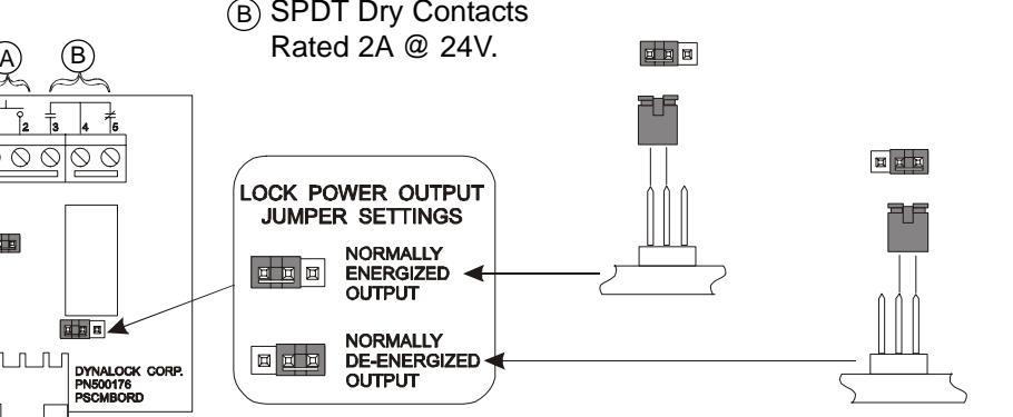
CM Option (Control Module)
(Factory Setting)
Accepts access/egress control dry contact input. Provides SPDT relay output.
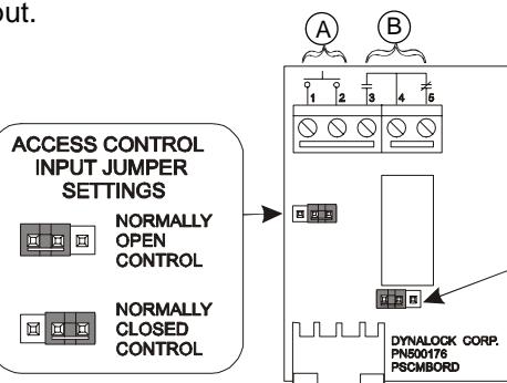
Without Control Module Option With Control Module Option
Access Control Input, Dry Contacts Only. A

MODEL #5500 POWER SUPPLY
INSTALLATION INSTRUCTIONS
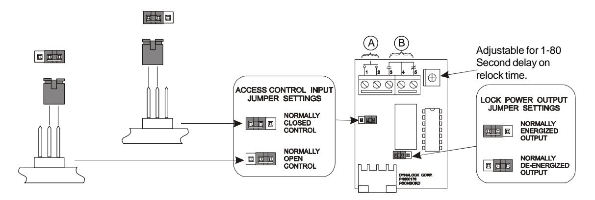
CMTD Option (Control Module with Time Delay)
Same as CM Option with Relock Time Delay
- A Access Control Input, Dry Contacts Only.
- SPDT Dry Contacts Rated 2A @ 24V.
ATS Option (Anti-Tamper Switch)
Contact held open with Enclosure cover closed.

Contact closed with Enclosure cover open.

NOTE: ATS switch contacts rated .25A @ 24V.
Installation Information LOCK CAPACITY CHART
123
|
S
in le F ul l g S iz e |
D
ub le F ul l o S iz e |
S
in le g |
D
ub le o |
S
in le D el g ay E g re ss |
D
d bo lt ea |
|
|---|---|---|---|---|---|---|
|
C
12 V D |
6 | 3 | 6 | 3 | 3 | 3 |
|
V
D C 24 |
8 | 4 | 8 | 4 | 3 | 4 |
CURRENT DRAW UP TO 1/2 AMP
|
Vo
lta ge |
A
W G 20 |
A
W G 1 8 |
A
W G 1 6 |
A
W G 1 4 |
A
W G 1 2 |
A
W G 1 0 |
|---|---|---|---|---|---|---|
|
V
D C 12 |
50
Ft |
1
00 Ft |
1
50 Ft |
2
50 Ft |
4
00 Ft |
7
50 Ft |
|
V
D C 24 |
0F
10 t. |
Ft
2 00 |
Ft
3 00 |
Ft
5 00 |
Ft
7 50 |
0F
1 50 t. |
* This chart indicatess minimum recommended wire size, but local codes prevail

MODEL #5500 POWER SUPPLY
INSTALLATION INSTRUCTIONS
TYPICAL APPLICATION
TROUBLESHOOTING
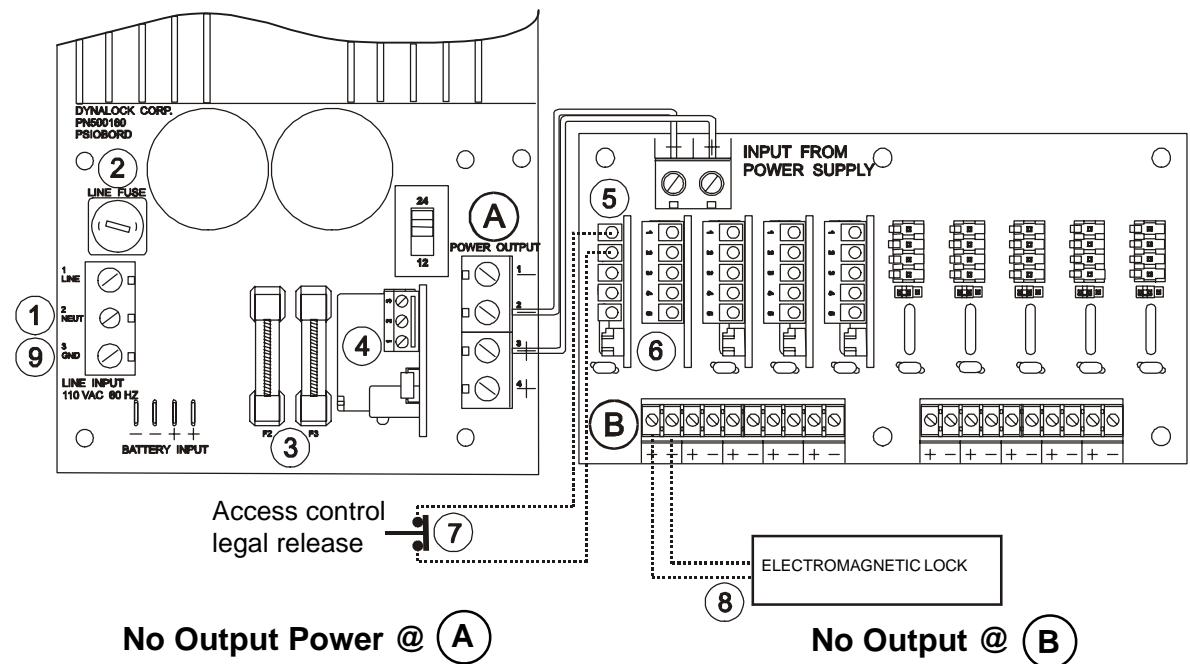
- 1 Check input line power.
- 2 Check line fuse.
- Check F2 & F3 output fuses.
- 4 Check FAC (If applicable) terminals 1 & 2 must be wired to N/C contact.
- Note: Start at ' No Output Power @ A
- Check jumper settings on CM/CMTD module(If applicable). 5
- Check jumper setting on DB-5/DB-10 card. 6
- Check for proper access switch contact status. 7
- Check load & external wiring for short condition.
- Reset Power Supply (With no load) by disconnecting input power at for 2 minutes. 1 9