DynaLock 5000 Series Power Supply Charger Installation Instructions
Open the original PDF document
View PDF

5000 SERIES POWER SUPPLY/CHARGERS INSTALLATION GUIDE
MODEL# 5025 (1 AMP @ 12VDC OR 24VDC)
MODEL# 5500 (3 AMP @ 12VDC OR 2 AMPS @ 24VDC)
MODEL# 5600-12 (10 AMPS @ 12VDC)
MODEL# 5600-24 (5 AMPS @ 24VDC)
IMPORTANT SAFETY INSTRUCTIONS
THIS MANUAL CONTAINS IMPORTANT SAFETY INSTRUCTIONS FOR POWER SUPPLY/BATTERY CHARGER MODELS: 5025, 5500, 5600-12, 5600-24
BEFORE USING THE BATTERY CHARGER, READ ALL INSTRUCTIONS AND CAUTIONARY MARKINGS ON THE BATTERY CHARGER, BATTERY/BATTERIES AND PRODUCTS USING BATTERIES
WWW.DYNALOCK.COM 705 EMMETT STREET BRISTOL, CT 06011-2728
PHONE: (860) 582-4761 FAX: (860) 585-0338
OVERVIEW
These access control power supply/chargers are specifically designed for use with access control systems and accessories. These units convert a 115VAC/50-60Hz input into two outputs (see options). Outputs will route power to a variety of access control hardware devices including Mag Locks, Electric Strikes, Magnetic Door Holders, ect. These outputs will operate in both Fail-Safe and Fail-Secure modes.
5000 SERIES POWER SUPPLY CONFIGURATION REFERENCE CHART
| DYNALOCK MODEL NUMBER |
12VDC
CURRENT OUTPUT |
24VDC
CURRENT OUTPUT |
OUTPUTS |
115VAC/60HZ INPUT
CURRENT DRAW |
INPUT FUSE
RATING |
AGENCY LISTINGS |
UL LISTINGS
& FILE NUMBERS |
|---|---|---|---|---|---|---|---|
| 5025 (12/24VDC FIELD SELECTABLE) | 1 AMP | 1 AMP | 2 | .45 AMPS | RESETTABLE | 3S84 | |
| 5500 (12/24VDC FIELD SELECTABLE) | 3 AMPS | 2 AMPS | 2 | 1 AMP | 1 AMP | MEA | File# E183665 |
| 5600 (12 OR 24VDC FIXED) | 10 AMPS | 5 AMPS | 2 | 2 AMPS | 4 AMPS |
Approved
NYCC Dept. Of Buildings |
# 23-92-E |
INSTALLATION INSTRUCTIONS
Wiring methods shall be in accordance with the National Electric Code/NFPA 72/ANSI, and with all local codes and authorities having jurisdiction. Product is intended for indoor use only.
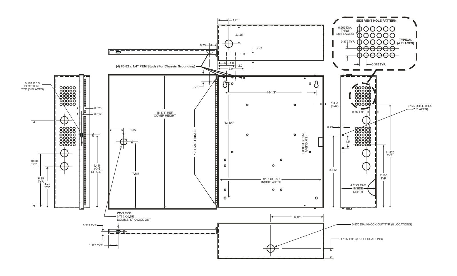
- 1) Mount unit in desired location. mark and pre-drill holes to line up with the top two keyholes in the enclosure. Install two upper fasteners and screws with screw heads protruding. Place the enclosures upper keyholes over the two upper screws, level and secure. Mark the position of the lower two holes. Remove the enclosure and drill the lower two holes. Place the enclosures upper key holes back over the two upper screws. Install the two lower screws and make sure to tighten all screws (Enclosure Dimensions, pg 12). Secure the enclosure to earth ground.
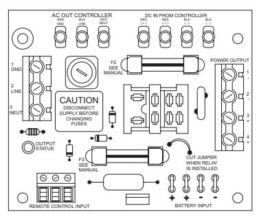
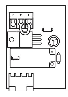
- 2) Set the output voltage: 5025, 5500 set the desired output voltage by setting the voltage selector to the appropriate position on the power supply main board.
Note: The 5600 is not field selectable and the output voltage must be specified when ordering.
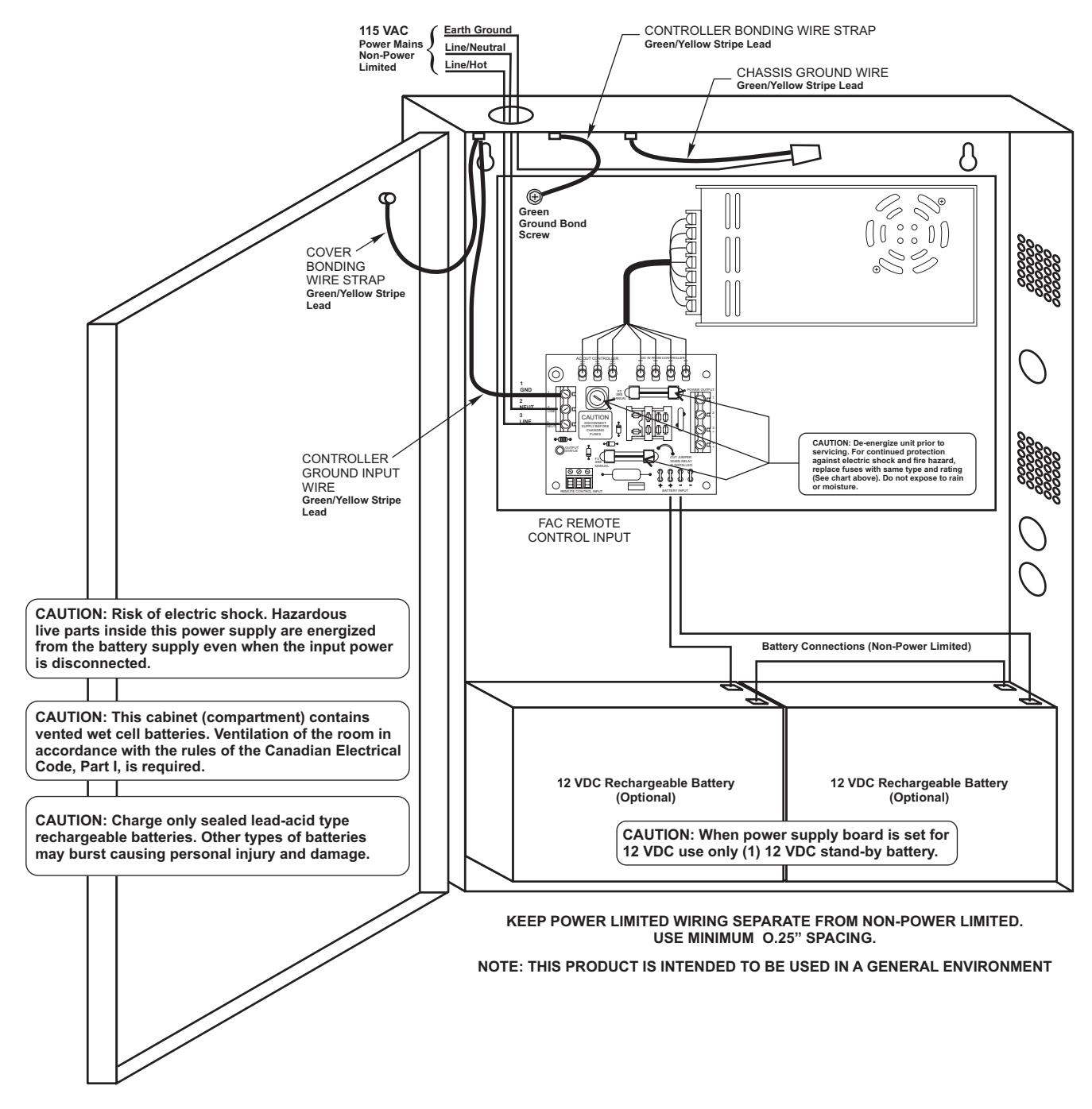
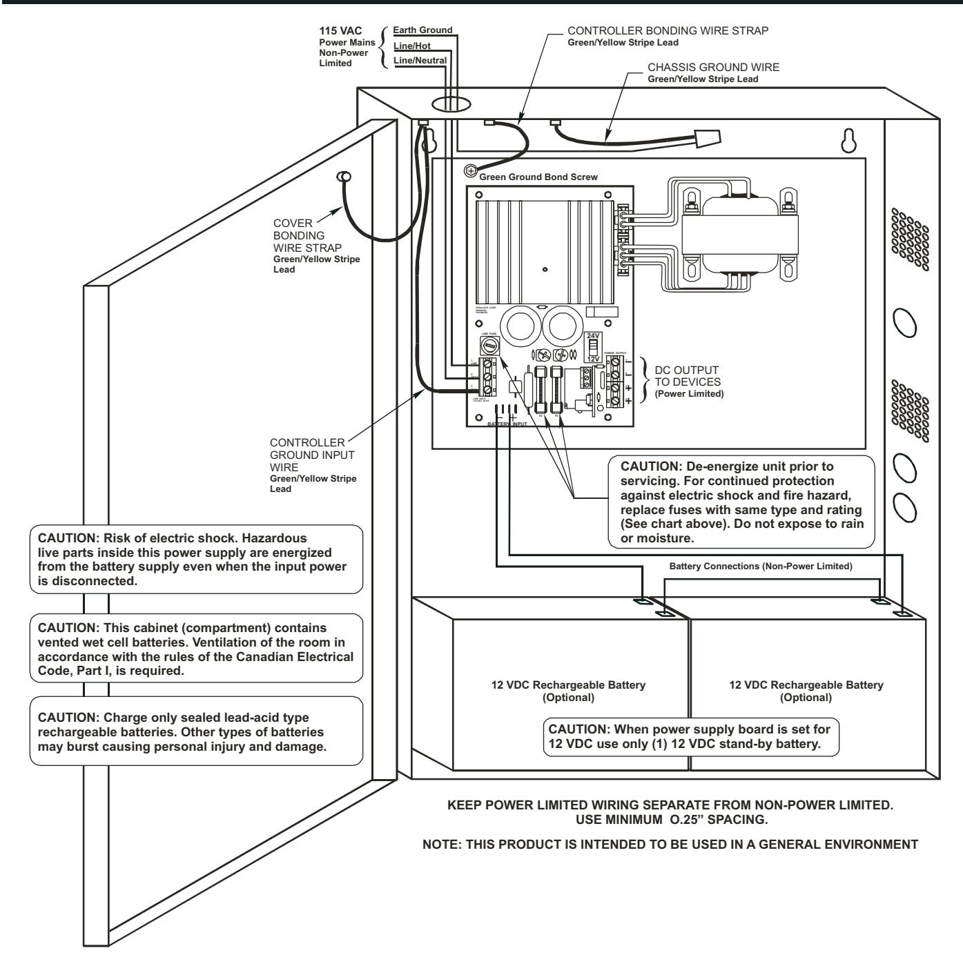
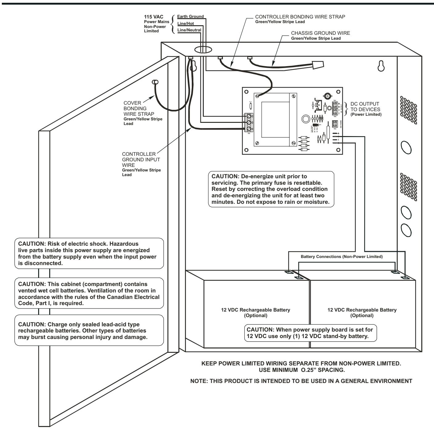
- 3) Secure green/yellow stripe lead to earth ground. Connect AC power (115VAC 60Hz) to terminals marked (H or L, G, N) on the power supply board. Use 18AWG wire or larger for all power connections (Battery, DC output, AC input).
- 4) Measure output voltage before connecting any devices. This will help prevent damage from occurring. Keep power limited wiring separate from non-power limited wiring (115VAC/60Hz Input, Battery Wires). Minimum .25" spacing must be provided.
- 5) Connect Fail-Safe or Fail-Secure type locking hardware (e.g. Door strikes, Mag Locks and Electric Deadbolts) positive leads to the terminals marked (+) DC OUTPUT and the negative leads to the terminals marked (-) DC OUTPUT.
INSTALLATION INSTRUCTIONS (CONT'D)
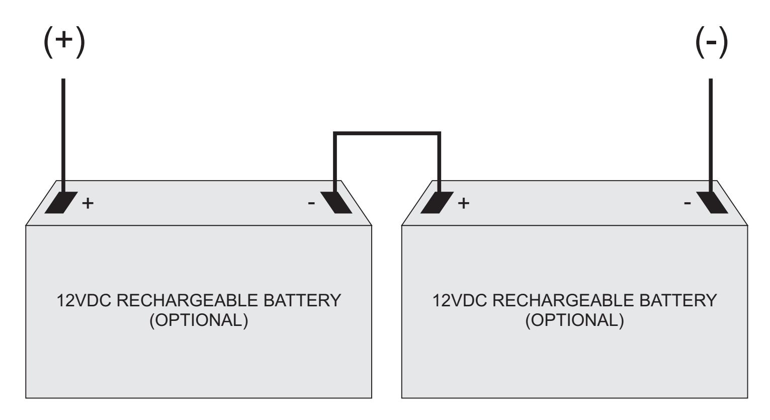
6) For access control applications, batteries are optional. When batteries are not used, a loss of AC voltage will result in the loss of output voltage. Batteries must be sealed lead acid rechargeable types if used. Connect one 12VDC battery to terminals marked (Battery) on the power supply board for 12VDC operations. Use two 12VDC batteries connected in series for 24VDC operations. Battery leads are included when batteries are ordered with the power supply.
7) Please insure enclosure cover is secured closed with the provided screw or the key lock option.
Units should be tested at least once a year for proper operation as follows:
Output Voltage Test: Under a normal load condition, the DC output voltage should be checked for a proper voltage level.
Battery Test: Under normal load conditions, check that the battery is fully charged, check specified voltage at the battery terminals and the board terminals to insure that there is no break in the battery connection wires.
Expected battery life is 5 years, however, it is recommended to change the batteries within two years or less if necessary.

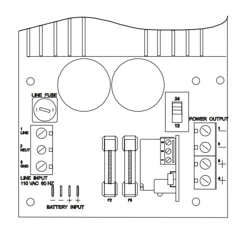
Dyna Lock MODELS 5600-12 / 5600-24 POWER SUPPLY/CHARGERS

| MODEL 5600-12 | MODEL 5600-24 | |
|---|---|---|
| INPUT POWER: | 115 VAC 50-60Hz, 2.0 Amp | 115 VAC 50-60Hz, 2.0 Amp |
| OUTPUT POWER: | 12 VDC Nominal (13.8 VDC) @ 10 Amp | 24 VDC Nominal (27.6 VDC) @ 5 Amp |
| PRIMARY FUSE: | 4A, 250V Slow-Blow | 4A, 250V Slow-Blow |
| OUTPUT FUSE: | (2) 12A, 250V Slow Blow | (2) 6A, 250V Slow Blow |


Note: Refer to 5000 Series Power Supply Installation Manual
DynaLock Corp. is not responsible for any typographical errors.

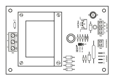
MODEL 5500 POWER SUPPLY/CHARGER

UL Listed General Purpose Power Supply
| MODEL 5500 | |
|---|---|
| INPUT POWER: | 115 VAC 50-60Hz, 1.0 Amp |
| OUTPUT POWER: | 12 VDC Nominal (13.8 VDC) @ 3 Amp or 24 VDC Nominal (27.6 VDC) @ 2 Amp |
| PRIMARY FUSE: | 1A, 250V Slow-Blow |
| OUTPUT FUSE: | (2) 5A, 250V Slow Blow |


Note: Refer to 5000 Series Power Supply Installation Manual
DynaLock Corp. is not responsible for any typographical errors.

MODEL 5025 POWER SUPPLY/CHARGER

UL Listed General Purpose Power Supply
| MODEL 5025 | ||||
|---|---|---|---|---|
| INPUT POWER: | 115 VAC 50-60Hz, 0.45 Amp | |||
| OUTPUT POWER: | 12 VDC Nominal (13.8 VDC) @ 1 Amp or 24 VDC Nominal (27.6 VDC) @ 1 Amp | |||
| PRIMARY FUSE: | Resettable PTCC | |||


Note: Refer to 5000 Series Power Supply Installation Manual
DynaLock Corp. is not responsible for any typographical errors.
5500/5600 OPTIONS
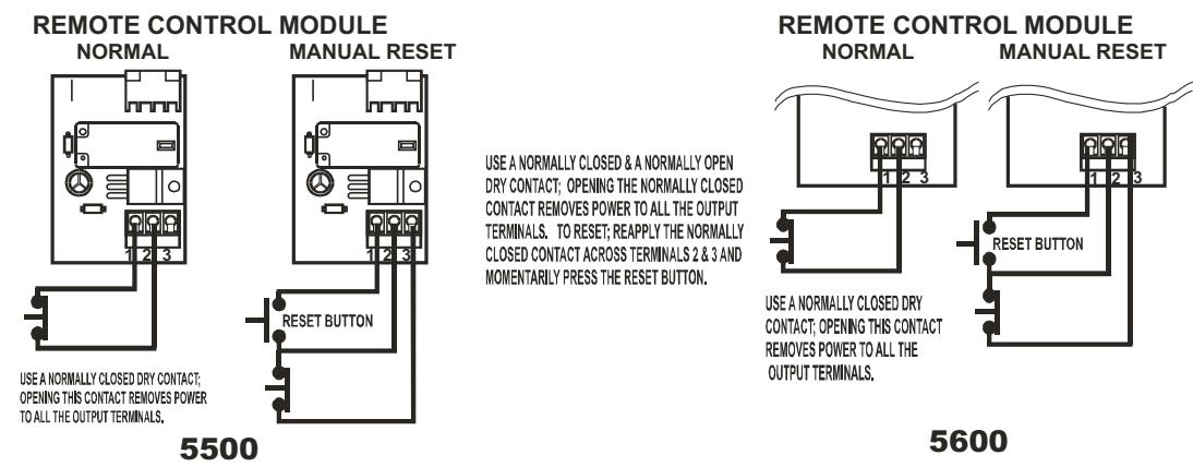
FAC Option (Remote Control)
Kills all voltage outputs when interfaced with remote dry contact.
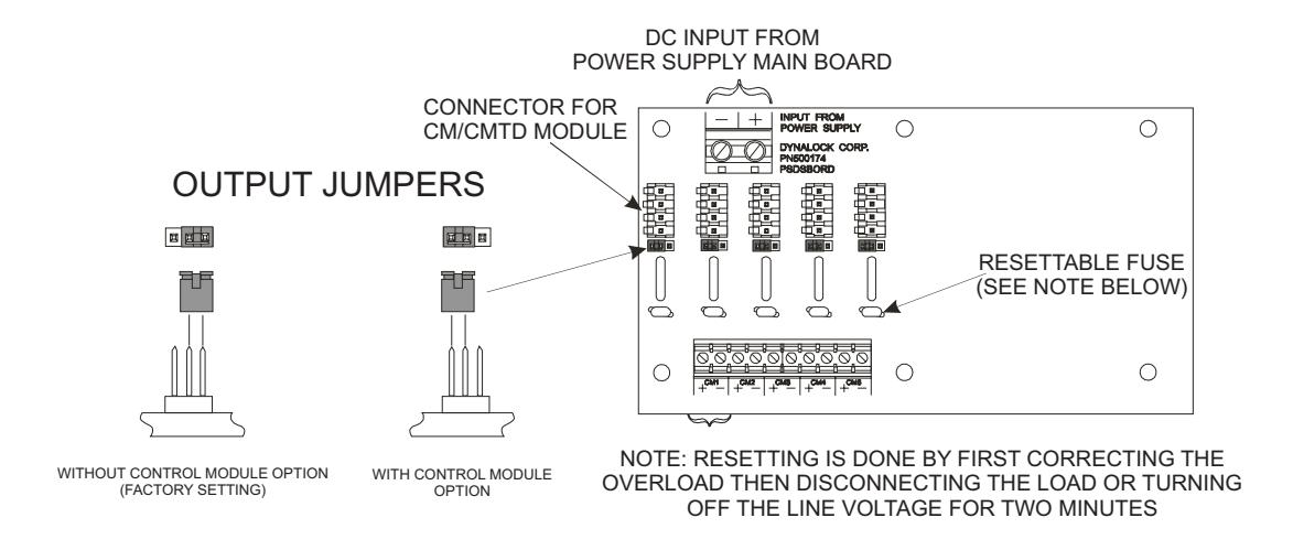
DB-5 & DB-10 Option (Distribution Board)
Two size distribution (5 or 10 position) are available to provide individually fused output terminals for each lock zone.
5500/5600 OPTIONS
CM Option (Control Module)
Accepts access/egress control dry contact input. Provides SPDT relay output.
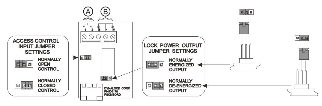
- A ACCESS CONTROL INPUT (DRY CONTACTS ONLY)
- B SPDT DRY CONTACTS RATED AT 2A @ 24V
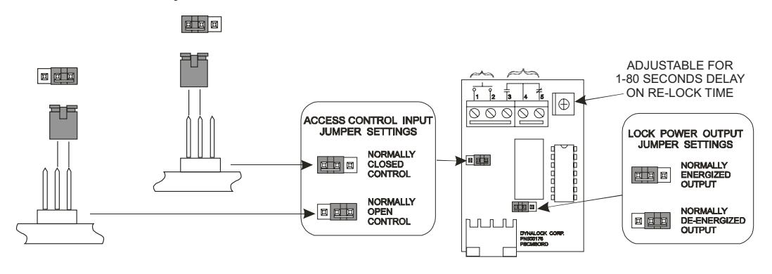
CMTD Option (Control Module with Time Delay)
same as CM Option with Relock Time Delay
ATS Option (Anti-Tamper switch)
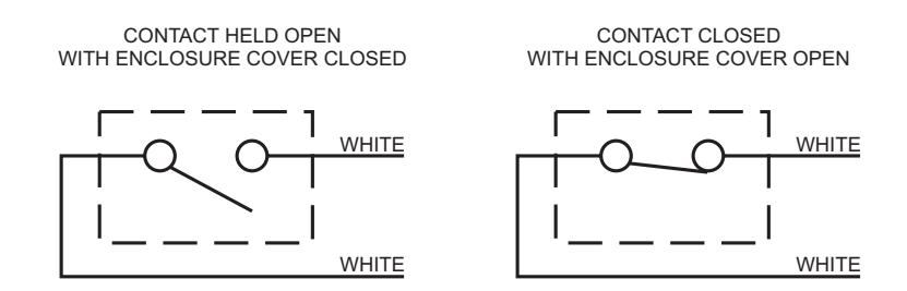
NOTE: ATS switch contacts rated .25A @ 24V
5500/5600 OPTIONS
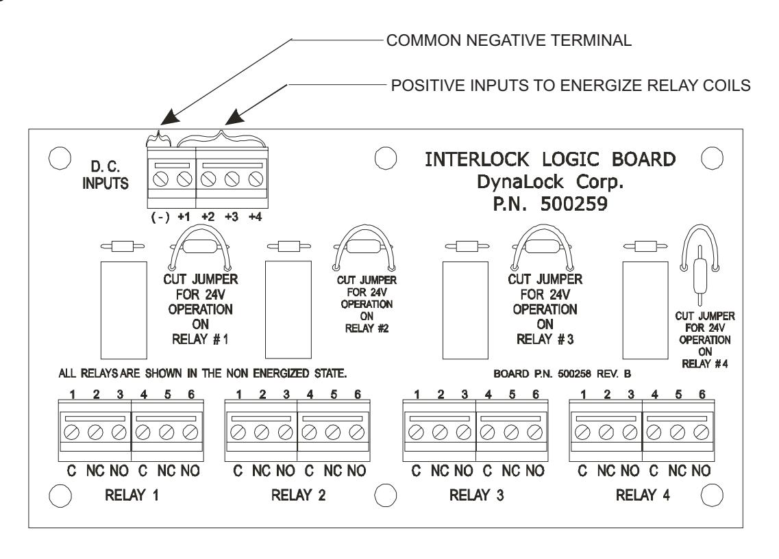
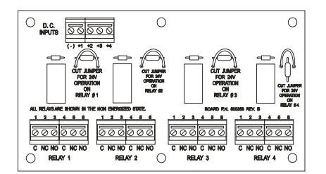
ILB Option (Interlock Logic Board) Provides Four DPDT Relay Outputs
Note: Separate ILB User Manual shows typical wiring diagrams.
INSTALLATION INFORMATION
5600 LOCK CAPACITY
| VOLTAGE |
SINGLE
(FULL SIZE) |
DOUBLE
(FULL SIZE) |
SINGLE | DOUBLE |
SINGLE
DELAY EGRESS |
DEADBOLT |
|---|---|---|---|---|---|---|
| 12VDC | 18 | 9 | 18 | 9 | 11 | 10 |
| 24VDC | 18 | 9 | 18 | 9 | 8 | 9 |
CURRENT DRAW UP TO 1/2 AMP
| VOLTAGE | 20 AWG | 18AWG | 16AWG | 14AWG | 12AWG | 10AWG |
|---|---|---|---|---|---|---|
| 12VDC | 50FT | 100FT | 150FT | 250FT | 400FT | 625FT |
| 24VDC | 150FT | 225FT | 350FT | 550FT | 900FT | 1375FT |
5500 LOCK CAPACITY
| VOLTAGE |
SINGLE
(FULL SIZE) |
DOUBLE
(FULL SIZE) |
SINGLE | DOUBLE |
SINGLE
DELAY EGRESS |
DEADBOLT |
|---|---|---|---|---|---|---|
| 12VDC | 6 | 3 | 6 | 3 | 3 | 3 |
| 24VDC | 8 | 4 | 8 | 4 | 3 | 4 |
CURRENT DRAW UP TO 1/2 AMP
| VOLTAGE | 20 AWG | 18AWG | 16AWG | 14AWG | 12AWG | 10AWG |
|---|---|---|---|---|---|---|
| 12VDC | 50FT | 100FT | 150FT | 250FT | 400FT | 750FT |
| 24VDC | 100FT | 200FT | 300FT | 500FT | 750FT | 1500FT |
These charts indicates the minimum recommended wire size, local codes prevail.
TYPICAL 5500/5600 APPLICATION
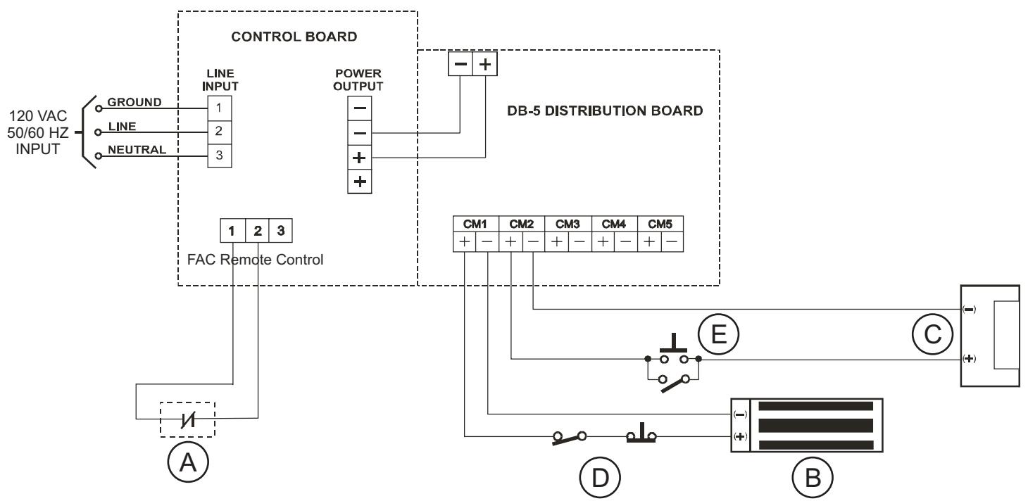
- A NORMALLY CLOSED DRY CONTACT FROM THE FIRE ALARM CONTROL PANEL (FROM OTHERS)
- B FAIL SAFE LOCKING DEVICE
- C FAIL SECURE LOCKING DEVICE
- D NORMALLY CLOSED ACCESS/EGRESS CONTROLS
- E NORMALLY OPEN ACCESS/EGRESS CONTROLS
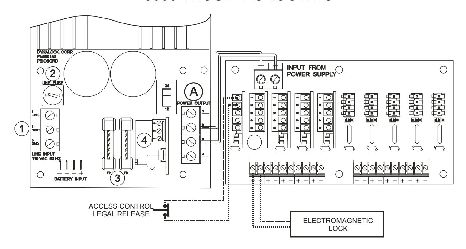
5600 TROUBLESHOOTING
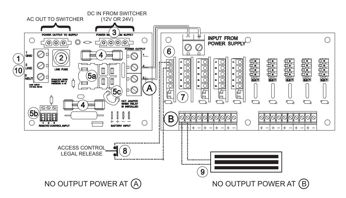
- CHECK INPUT LINE FUSE 1
- CHECK LINE FUSE 2
- CHECK FOR 12 OR 24VDC FROM SWITCHER 3
- CHECK FOR 12 OR 24VDC FROM SWITCHER 4
- CHECK F2 AND F3 OUTPUT FUSES CHECK THAT FAC MODULE IS SEATED 5a
- PROPERLY (IF APPLICABLE) TERMINALS 1 AND 2 MUST BE JUMPED 5b
- TOGETHER IF UNIT HAS FAC MODULE 5c
- CHECK JUMPER SETTING AY CM/CMTD MODULE (IF APPLICABLE) 6
- CHECK JUMPER SETTING AT DB-5/DB-10 CARD 7
- CHECK FOR PROPER ACCESS SWITCH CONTACT STATUS 8
- CHECK LOAD AND EXTERNAL WIRING FOR SHORT CONDITION 9
- RESET POWER SUPPLY (WITH NO LOAD) BY DISCONNECTING INPUT POWER AT AC LINE IN FOR 2 MINUTES 10
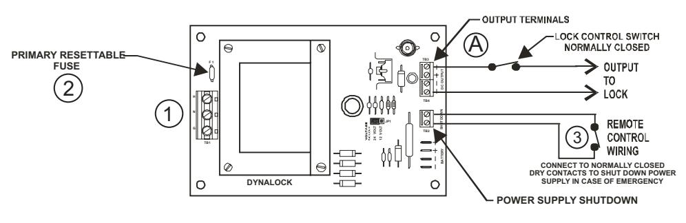
5500 TROUBLESHOOTING
- NO OUTPUT POWER AT (A)
- (1) CHECK INPUT LINE POWER
- (2) CHECK LINE FUSE
- (3) CHECK F2 & F3 OUTPUT FUSES
- 4 CHECK FAC (IF APPLICABLE) TERMINALS, 1 AND 2 MUST BE WIRED TO N/C CONTACT
5025 TROUBLESHOOTING
NO OUTPUT POWER AT (A)
- (1) CHECK INPUT LINE POWER
- (2) RESET POWER SUPPLY (WITH NO LOAD) BY DISCONNECTING POWER AT LEAST FOR 2 MINUTES
- (3) MAKE SURE YOU HAVE A CLOSURE BETWEEN THE 2 SHUT DOWN TERMINALS
POWER SUPPLY ENCLOSURE
5000 SERIES PART LIST
5600 12VDC P/N 500333
5600 24VDC P/N 500334
5500 P/N 500221
5025 P/N 500280
PRIMARY CIRCUIT BOARD PART NUMBERS
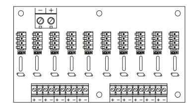
DB-10 DISTRIBUTION BOARD P/N 500229
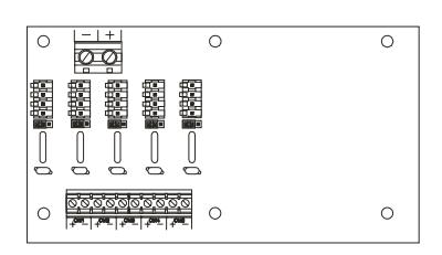
DB-5 DISTRIBUTION BOARD P/N 500228
ILB BOARD P/N 500259
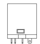
5600 REMOTE FIRE MODULE (FAC) PLUG IN RELAY
24VDC P/N 500303
12VDC P/N 500302
5500 REMOTE FIRE MODULE (FAC) PLUG IN RELAY P/N 500232
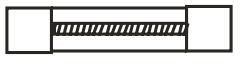
FUSES
1AMP P/N 500149 4AMP P/N 500332 5AMP P/N 500056 6AMP P/N 500203 12AMP P/N 500227
PLEASE DELIVER THIS MANUAL TO THE END USER UPON COMPLETION OF THE POWER SUPPLY INSTALLATION
FOR PRODUCT SUPPORT AND PARTS ORDERING INFORMATION CONTACT:
DynaLock Corp. 705 Emmett Street Bristol, CT 06010
Bus: (877) 396-2562 Toll-Free USA
(860) 582-4761 Fax: (860) 585-0338
DYNALOCK ON THE INTERNET:
E-mail: info@dynalock.com Website: www.dynalock.com

QQFU/QQFU7 Power Supplies, General Purpose