DynaLock 3006 Series Installation Instructions
Open the original PDF document
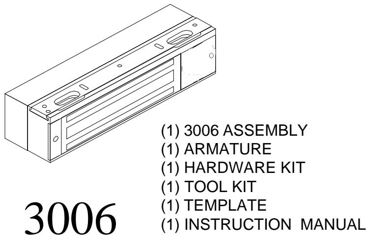
View PDF#3006 SERIES FREE-EGRESS ELECTROMAGNETIC LOCK MOUNTING and OPERATING INSTRUCTIONS
PLEASE READ BEFORE ATTEMPTING INSTALLATIONS
GENERAL MOUNTING INFORMATION
Attention to detail, familiarizing yourself with the actual door conditions and the following instructions will prove invaluable as you begin installation of this high quality lock. The lock must mount rigidly to the underside of the frame header and against the vertical jamb located opposite the hinge side jamb. The armature is designed to pivot slightly when mounted. The supplied hardware is for a standard 1-3/4" thick door.
? NOTE: This lock coil position may be changed to match the hand of the door, if required. Refer to
page 3 for instructions on how to convert the handing of this lock.
? NOTE: If this lock is supplied with the DSM feature, be certain to mount the armature with the DSM
block opposite the access cover.
HANDLING:
The Electromagnetic lock and armature are ruggedly constructed and designed to provide years of trouble free service, but care must be taken during installation and actual use that the PIR, lock face and armature face are free of dirt, rust, burrs, paint, or any other obstruction which may interfere with the lock and armature making good contact. NEVER TOUCH THE PIR LENS!
MAINTENANCE:
To insure peak lock performance, clean the lock and armature face with a mild detergent and a clean soft cloth, then apply a light coat of rust inhibitor such as WD40 to protect these surfaces. This need only be done when dirt buildup is noticed. DO NOT APPLY CLEANERS OR LUBICATION TO THE PIR LENS.
3006 THEORY OF OPERATION
The door is normally closed and latched by the existing mechanical door hardware and also magnetically secured by the 3006. When an individual attempting to egress approaches the door, the builtin Passive Infrared (PIR) Egress Sensor detects their presence and immediately releases the magnetic lock. Power to the 3006 may be interrupted as a means of manually unlocking the 3006 via a remote access or egress control device.
The PIR Sensor has proprietary electronics allowing it to remain active for up to one hour with no power applied. This eliminates warm up time normally required after a power interruption.
The 3006 Free egress electromagnetic lock, when interfaced with a request to exit button, complies with the code requirement specified in NFPA101 "Access Controlled Doors".
TABLE OF CONTENTS
The mounting, alignment and electronic connections described on the following pages should be performed in the order shown. The basic steps and information are on the pages indicated below:
| General | Page |
|---|---|
|
General Mounting Information
Handling Maintenance Theory of Operation |
1
1 1 1 |
| General Information on the PIR Sensor | 2 |
|
Mounting Instructions
Converting Hand of Lock Using the Template Exploded View Mounting the Armature Mounting the Baseplate ("FasTrak") and Lock Housing |
3
3 4 4 5 |
|
Parts location and wiring
Terminal Strip Description Controls and Parts Location PIR Sensor Adjustment Wiring Options Monitor Wiring12 Door Status Monitoring (DSM) Option Notes on Installation Bill of Material14 |
6
7 8 9-11 12 13 |
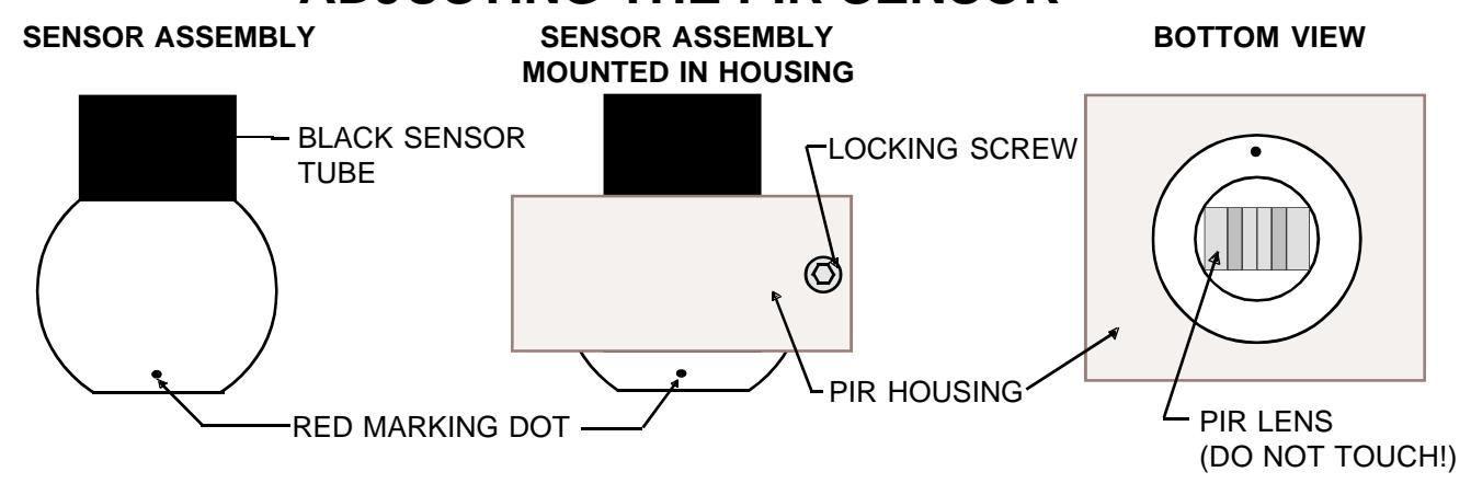
GENERAL INFORMATION ON THE PIR SENSOR
CAUTION: When handling the 3006, NEVER TOUCH THE PIR LENS!
PIR detectors are sensitive to changes in infrared energy caused by an object moving across a sensors field of view. Detection depends on the difference between the infrared energy transmitted by the moving object and the temperature of background objects. It is recommended that the 3006 NOT be installed in the following locations:
- ? Outdoors.
- ? Where the PIR sensor face is exposed to direct sunlight.
- ? Locations which are subjected to rapid temperature changes.
- ? Locations which are subjected to extreme vibration.
- ? Where push carts or similar objects come before the person entering the PIR's detection path.
- ? Areas where ambient temperature is near surface body temperature (85 95 degrees F)
The 3006's PIR Sensor is manufactured with a state-of- the-art detector, incorporating special detection and rejection features. Below are some of these features:
- ? Single step detection.
- ? RF immunity up to 1000 MHz.
- ? Light rejection filter to reject visible light variations.
CONVERTING HAND of LOCK
The hand of the 3006 lock may be changed to match RHRB or LHRB outswinging doors. Locks are shipped as RHRB style shown below. If your installation requires a LHRB lock continue with the following instructions.
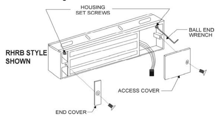
A. Remove the access and end covers. Using the 1/8" ball end hex wrench provided, loosen both housing set screws approx. 3 turns. (DO NOT REMOVE FROM HOUSING).
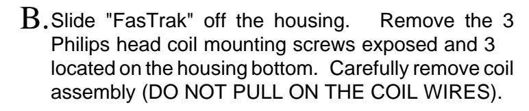
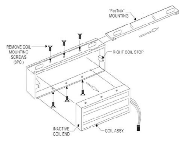
Rotate the coil assembly 180 Degrees and re-install it with the inactive end against the right coil stop. Re-install the 6 coil mounting screws where threaded holes are visible. C.
USING THE TEMPLATE
- 1. Use the proper side of the supplied template to accomodate the hand of the door and lock.
- 2. Fold the template on the dotted line to form a 90 degree angle. Scoring the template with a straight edge and a screwdriver will make it fold easier. With the door in the fully closed position, place the template against the header and door with one edge of the template against the vertical lock jamb. Use tape to hold the template onto the frame.
- 3. Transfer all holes locations to both door and header.
- 4. Proceed to page 4 & 5 for Armature and Lock Mounting Instructions.
Prepare the door for ARMATURE MOUNTING
From the three illustrations below select one that resembles your door type, and follow the instructions for the armature screw mounting hole. (See Template).
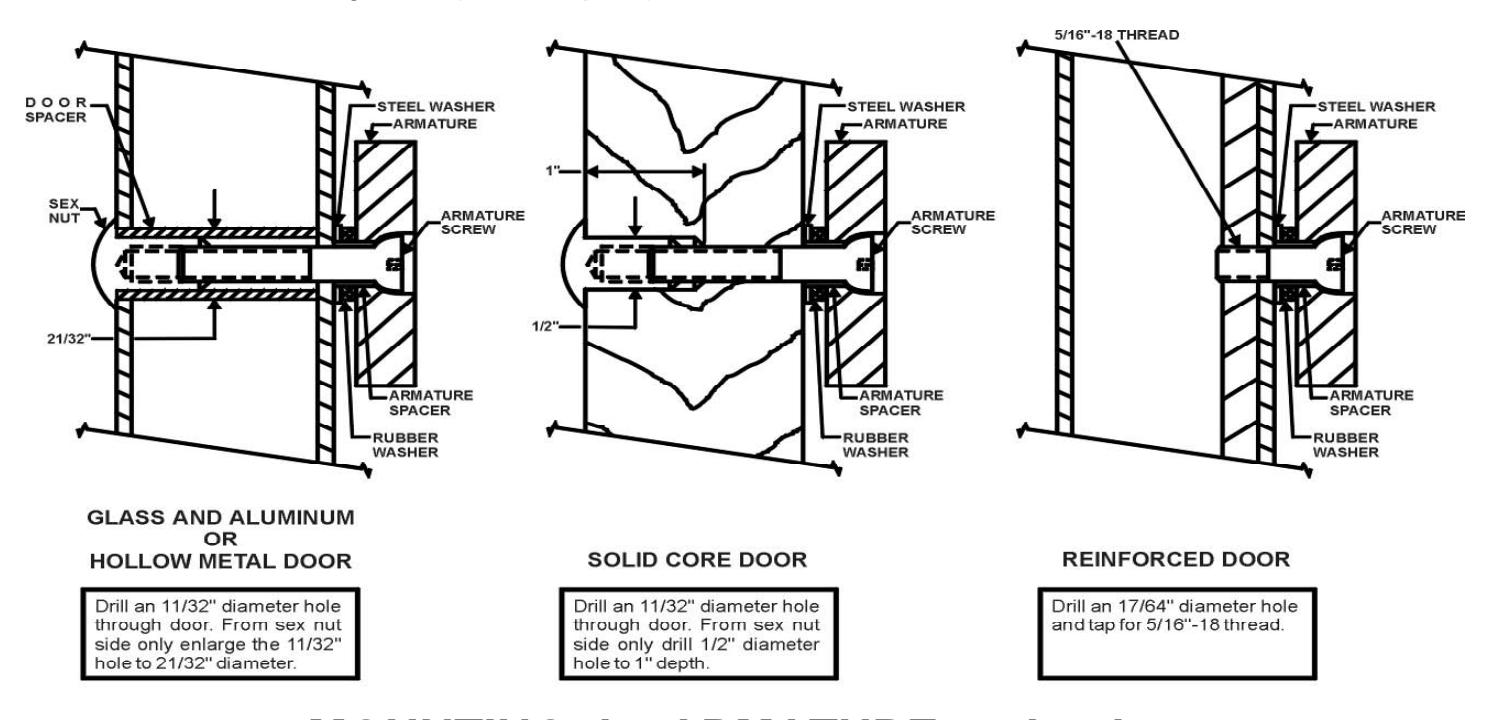
MOUNTING the ARMATURE to the door
Locate the 2 anti-spin pins from the armature screw pack. Place the armature face-down on a soft surface (ie; the shipping carton) and drive the 3/16" dia. anti-spin pins into the 2 holes provided. Refer to illustrations above to verify the correct assembly of mounting hardware and mount the armature to the door. The center screw should be finger tight plus 1/8" to 1/4" turn with Hex wrench. Failure to properly secure an armature to the door could result in serious injury or security breach.
page 4
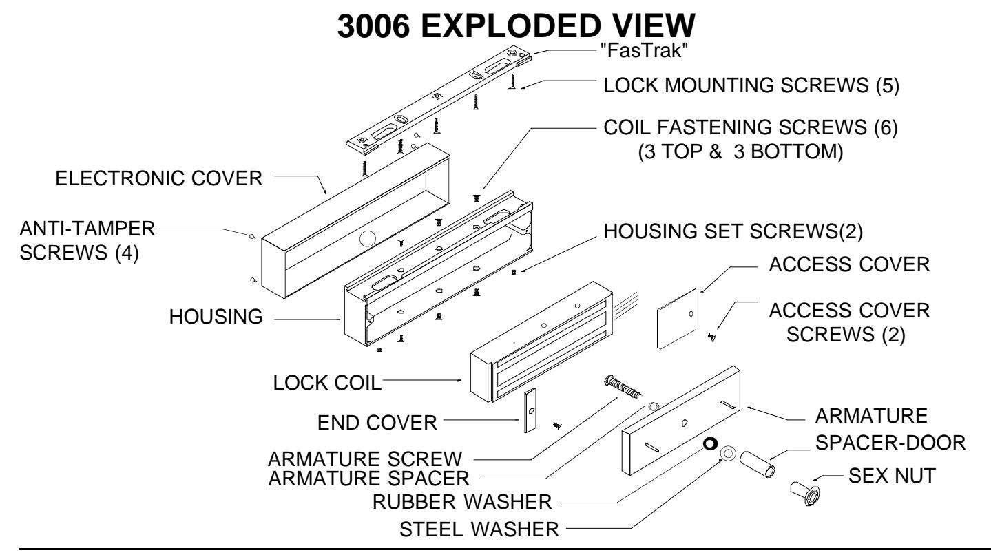
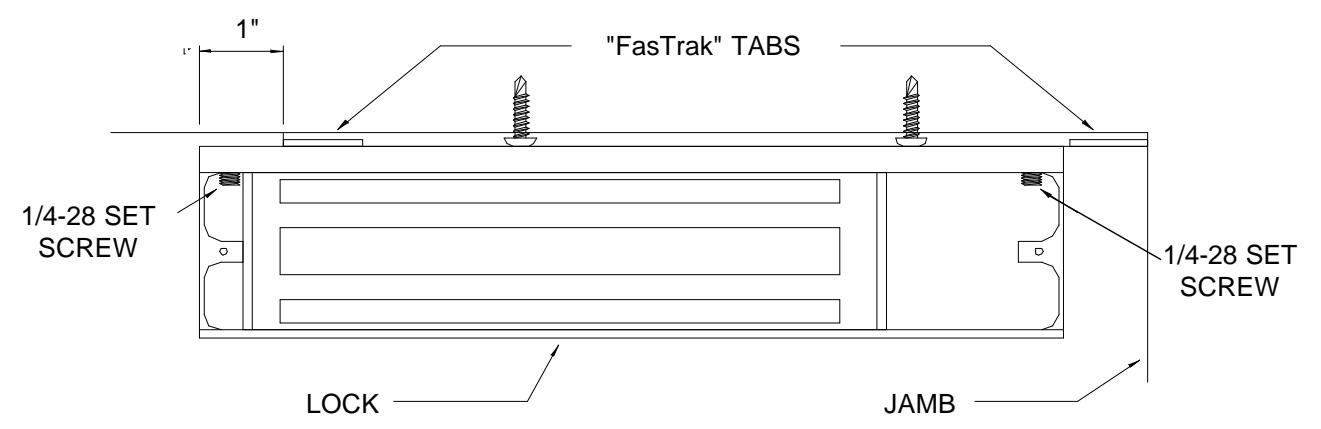
MOUNTING THE "FASTRAK" AND HOUSING
- 1. If you haven't done so yet remove the FasTrak mounting plate. Refer to the exploded view, top of page 4 and the following. Remove the electronics cover secured with the four snake eye anti-tamper # 6-32 screws. Remove the end and access covers each secured with a # 8- 32 philips screw. Loosen the 1/4-28 set screws in the upper inside corner of each end of the housing using the 1/8" ball end allen wrench supplied. Remove the FasTrak mounting plate.
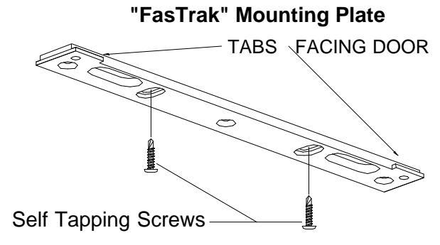
- 2. Referring to the Template, drill two 1/8" dia. lock mounting holes and one 9/16" wiring hole in the header where indicated.
- 3. Place the "FasTrak" against the header with the counter-sunk slots visible, and the tabs facing the door. Using a screwgun or electric drill with a philips bit, attach the "FasTrak" to the header at both slotted locations with the self tapping screws provided. Tighten the screws just snug enough to allow for final adjustment.
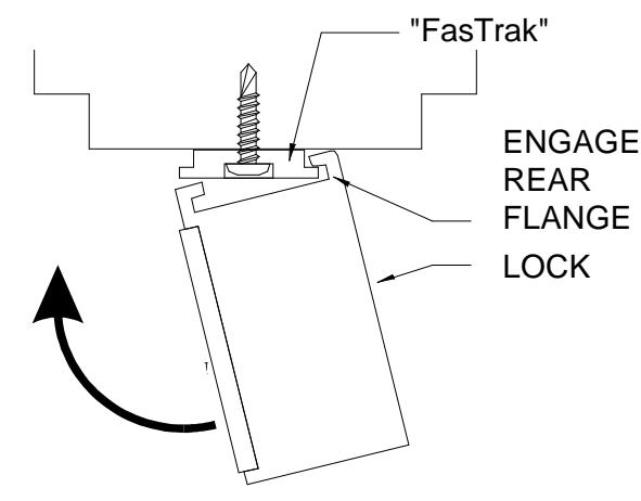
- 4. Temporarily mount the lock to the "FasTrak" by offsetting the lock one inch, tipping the front of the lock down engage the rear flange, rotate the lock up to vertical, and slide into position. Close and latch the door. Check that the armature and lock make full contact. If any adjustment is required, gently tap the housing with a soft rubber mallet until full contact is achieved, be careful not to damage the electronics circuit board. The head of the armature mounting screw must not project beyond the face of the armature. Open the door, remove the lock from the "FasTrak" and tighten both adjustment screws. Drive the remaining three screws into the header using the FasTrak as the template. Screw heads must not project above the "FasTrak".
- 5. Re-install the lock on the "FasTrak". Slotted wiring holes will allow the housing to be installed without interference. Using the 1/8" ball end wrench firmly tighten both 1/4-28 housing set screws and re-install the end and access covers.
Mounting the Lock
3006 TERMINAL STRIP DESCRIPTION
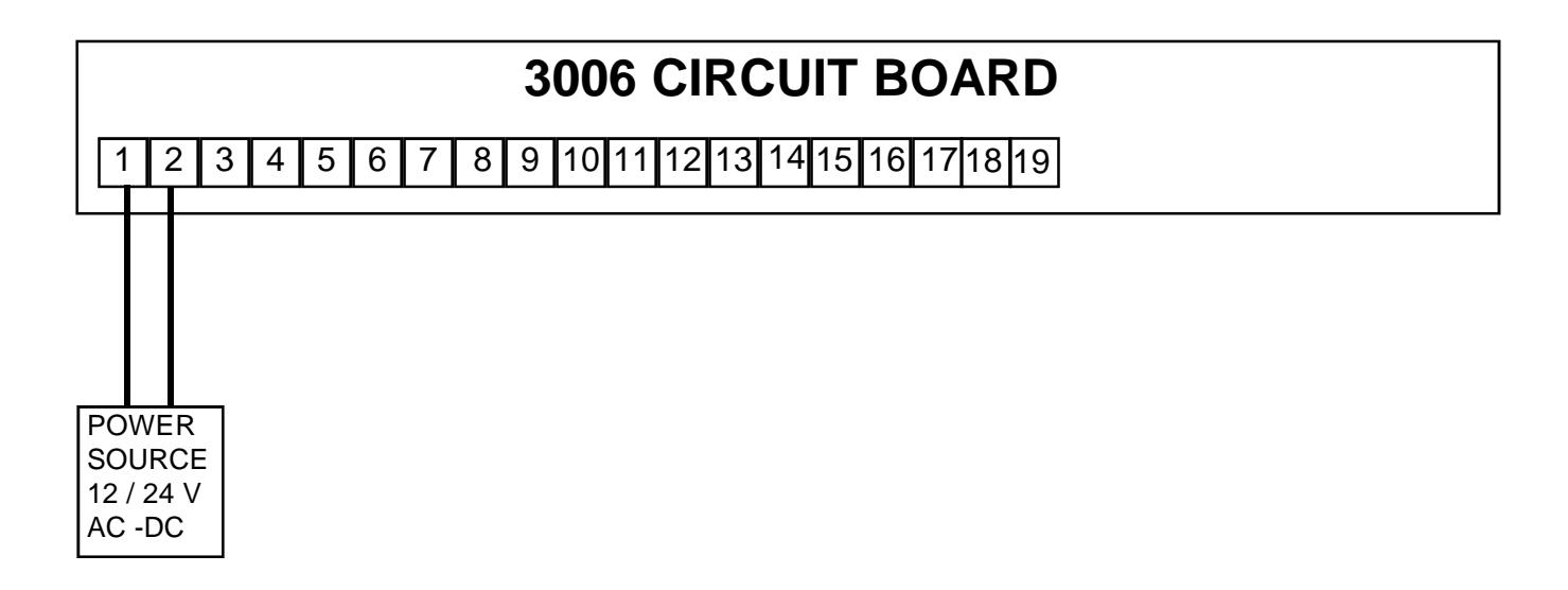
PINS 1,2 POWER INPUT , 12 or 24 volts AC/DC, Selectable through a jumper setting. The current requirement is .70 amps for 12 volts and .4 amps for 24 volts.
PINS 3,4 ACCESS CONTROL INPUT , Momentarily opening a NORMALLY CLOSED DRY CONTACT will release the 3006. The relock time is adjustable from 2-10 seconds.
PINS 5,6 EXTERNAL EGRESS DEVICES INPUT, Momentarily opening a NORMALLY CLOSED DRY CONTACT will release the 3006. The 3006 will remain unlocked for 35 seconds. An on board jumper will allow the relock time delay to be adjustable from 2-80 seconds.
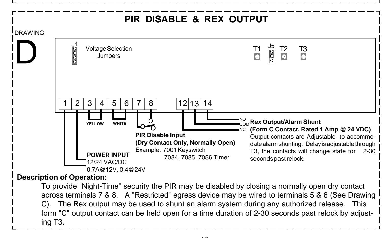
PINS 7,8 SENSOR DISABLE INPUT, A contact closure allows the 3006 to release only by an external access or egress device. The PIR will stay disabled as long as the contact closure is across pins 7 and 8. Once the closure is removed the PIR will be activated immediately, no warm up time. This input is designed to allow the 3006 to be a free-egress lock for a period of time during the day and a regular mag-lock at night. Typically, this function is controlled by an external time clock or similar control device.
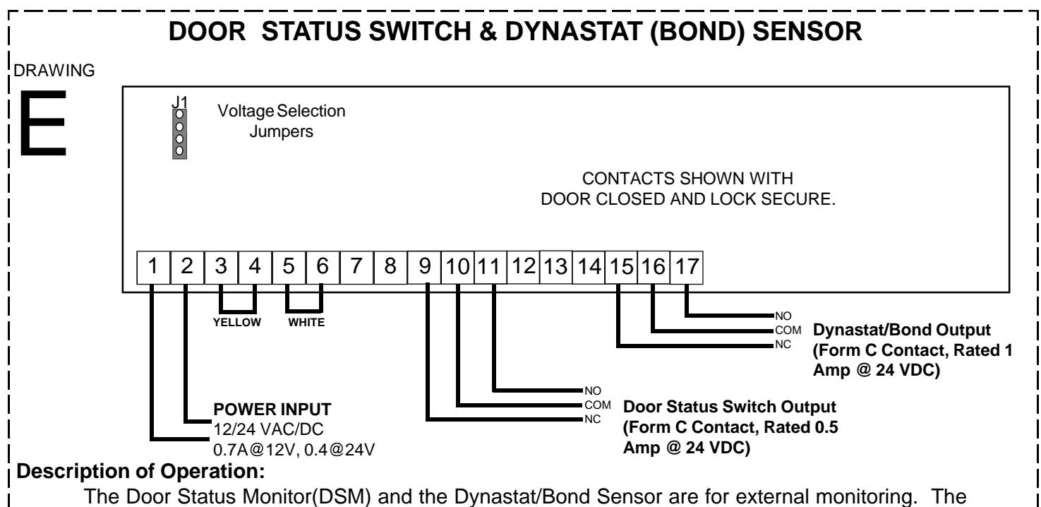
PINS 9,10,11 DSM MONITOR OUTPUT (DOOR STATUS MONITOR) (optional). Pin 9 is normally closed, 10 is common and 11 is normally opened. The contacts change state when the door is opened. Contact Ratings 0.5 Amp @ 24 VAC
PINS 12,13,14 REX OUTPUT , pin 12 is normally closed, 13 is common and 14 is normally opened. The state will change when the 3006 is unlocked, and will remain in that state for 1-30 seconds past relock. This output may be used for external alarm shunting. Contact Rating 1 Amp @ 24 VAC
PINS 15,16,17 DYNASTAT (BOND) MONITOR OUT-PUT , (optional) pin 15 is normally closed, 16 is common and 17 is normally open. The state will change when the lock coil is turned off by the PIR, Access Control Input, External Egress Inputs or Power Loss. This option is used in security applications to monitor the secure/not secure conditions of the lock. Contact Ratings 1 Amp @ 24 VAC
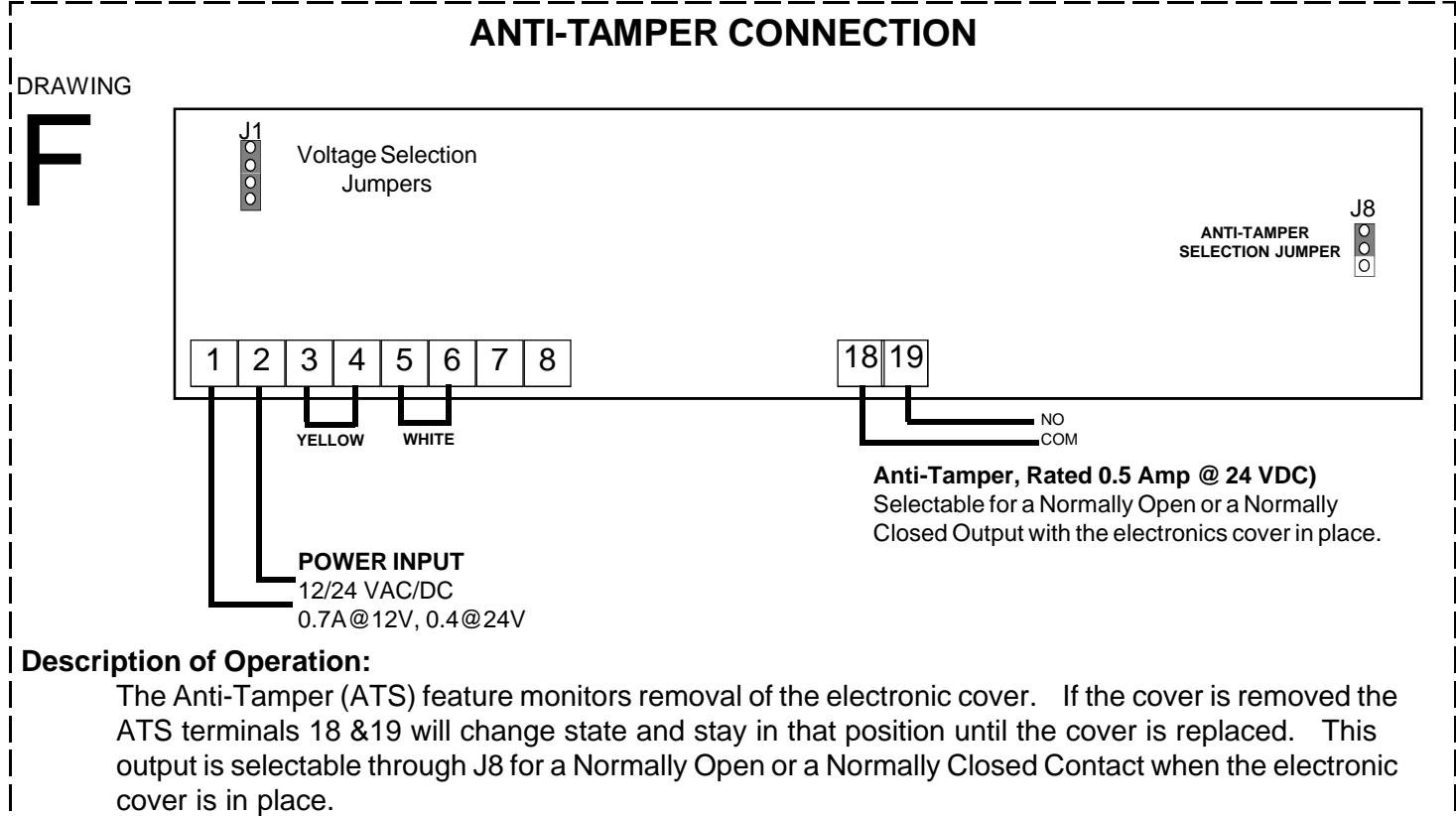
PINS 18,19 ANTI-TAMPER OUTPUT . This option provides normally open or normally closed contacts, selectable thru a jumper. Removal of the electronic cover will change the state of the contacts. Contact Ratings 0.5 Amp @ 24 VAC
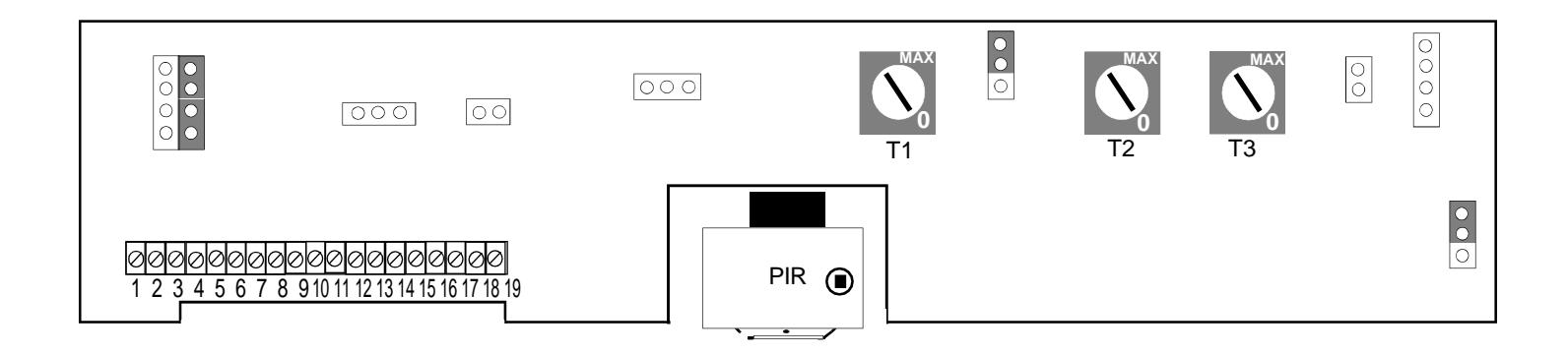
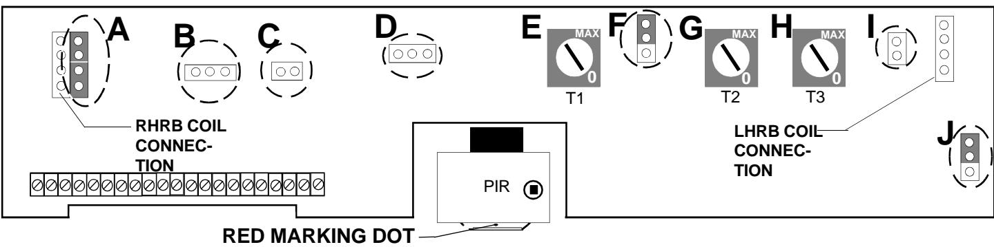
3006 CONTROLS AND PARTS LOCATIONS
Indicates the Front of the sensor assembly and must face the interior regardless of adjustment.
A. VOLTAGE SELECTION JUMPERS. Selects operating voltage of the lock coil. See above for jumper

- B. DOOR STATUS MONITOR INPUT (DSM) (OPTIONAL). Input connector for the DSM switch.
- C. DYNASTAT (BOND) SENSOR (OPTIONAL). The bond sensor from the lock coil is connected at this point, for a LHRB lock. Two conductor white harness.
- D. LED CONNECTOR. Allows the installer to disconnect the Led/Electronic cover from the circuit board.
- E. ACCESS CONTROL & PIR RELOCK TIMER. Adjusts the relock time delay from 2-10 seconds. Turn pot clockwise to increase time delay.
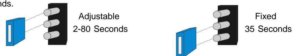
- F. EXTERNAL EGRESS JUMPER. Selects between a fixed 35 seconds or an adjustable delay of 2-80 seconds.
- G. EGRESS CONTROL RELOCK TIMER. Adjusts the relock time delay from 2-80 seconds when the external egress jumper is in the adjustable position (See F). Turn pot clockwise to increase time delay.
- H. REX OUTPUT TIMER CONTACTS (ALARM SHUNT). Adjusts the time delay of the alarm shunt relay contacts 2-30 seconds past relock. Turn pot clockwise to increase time delay.
- DYNASTAT (BOND) SENSOR (OPTIONAL). The bond sensor from the lock coil is connected at this point for a RHRB lock
- J. ANTI-TAMPER (ATS)SELECTION JUMPER (OPTIONAL). Changes the ATS option from Normally Open to Normally Closed contact output.

ADJUSTING THE PIR SENSOR
The PIR SENSOR can be adjusted to produce a variety of detection patterns. Figure 1.1 shows an approximate pattern for a 7'-0' door.
7 ft. 7 ft. 6 ft. 4ft. Max-
Figure 1.1 Typical pattern for a 7'-0' door.
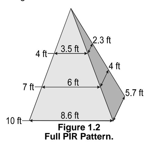
The Full PIR pattern is shown in figure 1.2 based on different heights.
The entire pattern can be shifted 20 degrees from centerline in all directions by adjusting the sensor as shown in figure 1.3
- 1. Remove the electronic cover from the lock.
- 2. Loosen the LOCKING SCREW, using the supplied 7/64"Allen wrench, until the BLACK SENSOR TUBE can be easily moved. DO NOT TOUCH THE PIR LENS! The BLACK SENSOR TUBE is mounted in a ball and socket. Use the Black Tube to adjust the Sensor Assembly.
- 3. Perform a walk test by approaching the opening and observing the detection pattern. The Led will turn from red to green and the lock will release prior to reaching the door when adjusted properly. Adjust the sensor tube accordingly to achieve desired operation. Re-tighten the Locking Screw.
- 4. Re-install the electronic cover and perform a final walk test to insure proper PIR alignment.
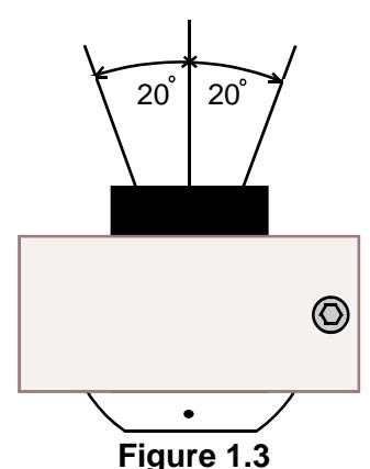
Figure 1.3 PIR Pattern Adjustment.
WIRING OPTIONS FOR THE 3006
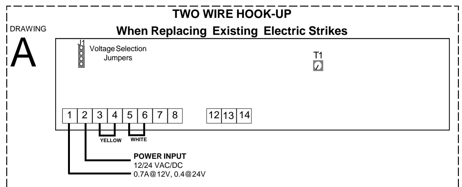
Description of Operation:
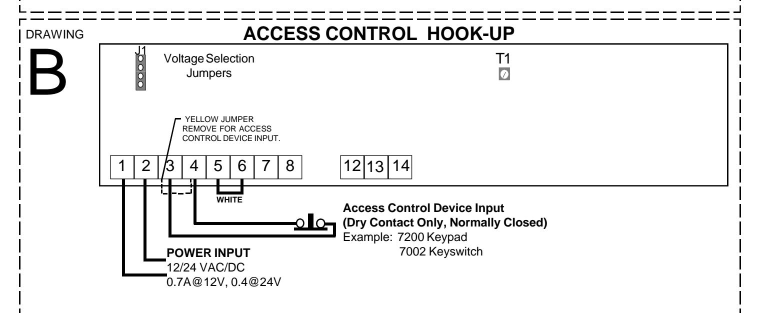
The 3006 is ideal for retrofitting of electric strike installations. It offers a higher degree of security and can be powered and controlled from the two existing wires when connected to terminals 1 & 2. Proprietary electronics allow the PIR to stay active for up to one hour, during a power interruption. Check that the voltage selection jumpers are properly set to match the input power. Immediate egress is achieved by the built-in PIR detector. Relock time delay may be set for 2-10 seconds by adjusting T1. If an Access Control device is required for ingress see drawing B.
Description of Operation:
Access control requires removing the yellow jumper and connecting a normally closed dry contact across terminals 3 & 4. Input power wires are connected to terminals 1 & 2. Check that the voltage selection jumpers are properly set to match the input power. Immediate egress is achieved by the built-in PIR detector. Relock time delay for the access control and the PIR may be set for 2-10 seconds by adjusting T1.
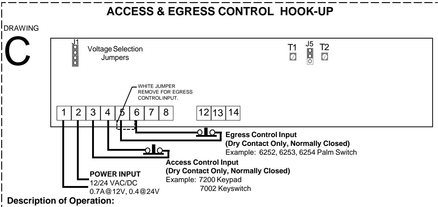
An Egress Control additional to the PIR requires removing the WHITE jumper and connecting a normally closed dry contact across terminals 5 & 6. The Egress Control Relock Delay is adjustable from 2-80 seconds through T2, when the External Egress Jumper (J5) is in the adjustable position. If J5 is in the fixed position there will be a fixed relock delay of 35 seconds. For description of the Access Control Input see diagram B.
ANTI-TAMPER CONNECTION DSM's form C contact will change state when the door is opened, and return to its original position once the door is closed. The Dynastat Sensor's form C contact will change state when the lock has been unlocked, and will return to its original state when relocked and properly bonded.
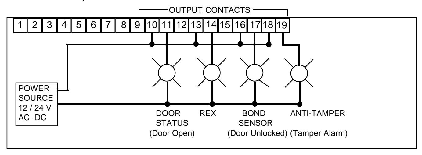
MONITOR WIRING
Monitoring the lock may consist of horns, audibles, lights etc. The diagram below shows a suggested way of wiring light indicators for a fully loaded 3006.
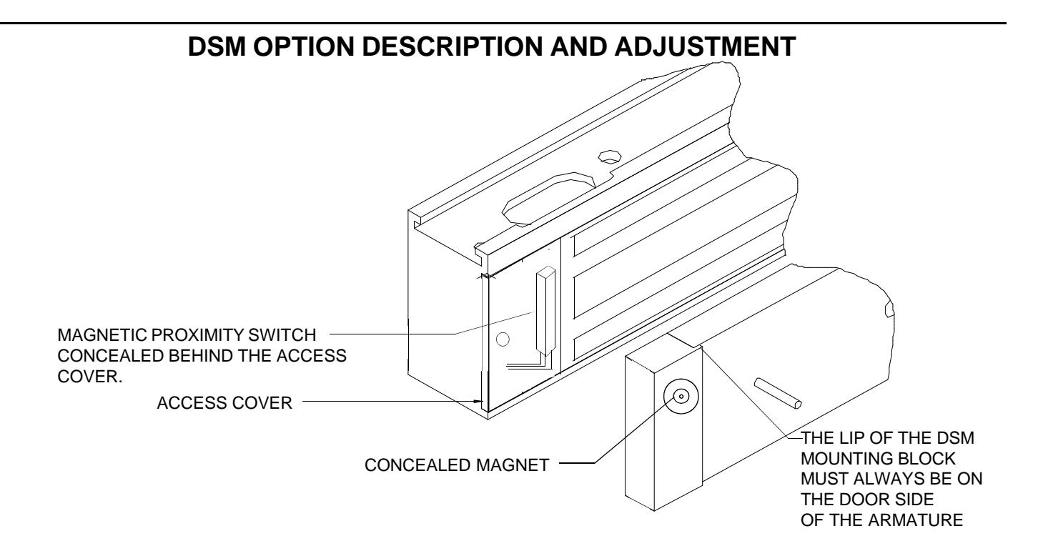
- 1. The DSM option is fixed for maximum sensitivity. A magnetic proximity switch is concealed behind the access cover.
- 2. The DSM Block contains a hidden magnet. When the door is closed the magnet is brought into close proximity to the access cover and activates the proximity switch thus producing a signal indicating a change in door position.
NOTES ON INSTALLATION:
SKETCH IN ALL CONNECTIONS FOR FUTURE REFERENCE OF INSTALLATION
3006 SERIES BILL OF MATERIAL
HARDWARE KIT CONTENTS
- 1 SEX NUT
- 1 DOOR SPACER
- 1 ARMATURE SPACER
- 1 STEEL WASHER
- 1 RUBBER WASHER
- 2 SPIN PINS 3/16 x 1"
- 1 ARMATURE SCREW
- 5 #10 TEK SCREWS
(Fast-Track mounting)
TOOL KIT CONTENTS
2 ALLEN WRENCHS 1/8 & 7/64 1 SNAKE EYE SCREW DRIVER
REQUIRED TOOLS
DRILLS 7/64, 1/8, 5/16, 11/32, 9/16, 21/32 PHILLIPS DRIVER #2 3/16" ALLEN WRENCH
OPTIONS CHECK OFF
DYN
DSM
ANTI-TAMPER
SF
BUILT WITH PRIDE BY
If any problems or questions arise while installing the 3006 please contact DynaLock's Customer Service Department @ 860-582-4761, or your local representative.
Thank you for using DynaLock's Electronic Security Hardware.