DynaLock 2853 2855 Series Installation Instructions
Open the original PDF document
View PDF

MODEL 2853/2855 DOOR HOLDER EXTENSIONS
INSTALLATION INSTRUCTIONS
Description
DynaLock 2853 & 2855 Door Holder Extension Kits are used where it is desired to hold doors open and where a standoff distance between the magnet assembly and the armature base is required. The extension rod kits can be used with models 2803, 2804, 2805 and 2806 Series Door Holders. Parts from these door holders are used with the extension kits to form a complete unit.
Specifications
| Model Number | Extension Range |
|---|---|
| 2853 | 6.37 - 8.00" (162 - 203 mm) |
| 2855 | 8.37 - 12" (213 - 305 mm) |
Installation
WARNING
The extension kits project a significant distance from the doors they are mounted on and should, therefore, be mounted as high as possible to preclude interference or personal injury.
-
Install the extension kit as follows.
- a. Remove the #10-32 x 1 1/2" (38 mm) armature securing screw and remove the catch plate from the armature base (Figure 1).
- b. Insert spherical bushings (removed in Step 1.a) as shown in Figure 2. If bushings are damaged, replace with bushings supplied with the door holder extension kit.
- Insert the extension rod into the armature base and secure with #10-32 x 1 1/2" (38 mm) armature securing screw (Figures 1 and 2).
- d. Insert spherical bushings (supplied) and flat washers (supplied) into the extension rod assembly as shown in Figure 2. Secure catch plate in extension rod using #10-32UNF x 1" (25 mm) securing screw (Figure 2).
- e. Adjust the extension length by loosening the knurled locking nut, extending the rod to the desired length and retightening the knurled locking nut (Figure 2).
NOTE: Proper alignment of the catch plate and the electromagnet helps ensure sufficient holding force.
- f. Align the catch plate with the electromagnet by moving the extension arm up or down and back or forth while simultaenously adjusting the catch plate against the magnet. There should be no gap between the catch plate and the magnet.
-
g. After the desired extension length and contact alignment have been achieved, perform the following (Figure 2):
- Using a 5/32" (4 mm) Allen Wrench (supplied), lock the extension arm into position by tightening the armature securing screw (Figure 2). Do not overtighten.
- h. Perform an operational check of the Electromagnetic Door Holder as outlined in the installation instruction provided with the door holder.
- 2. For more detailed information on installation of the door holders, see the instructions supplied with the door holder.
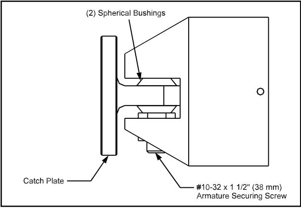
Figure 1. Armature Base Assembly

MODEL 2853/2855 DOOR HOLDER EXTENSIONS
INSTALLATION INSTRUCTIONS
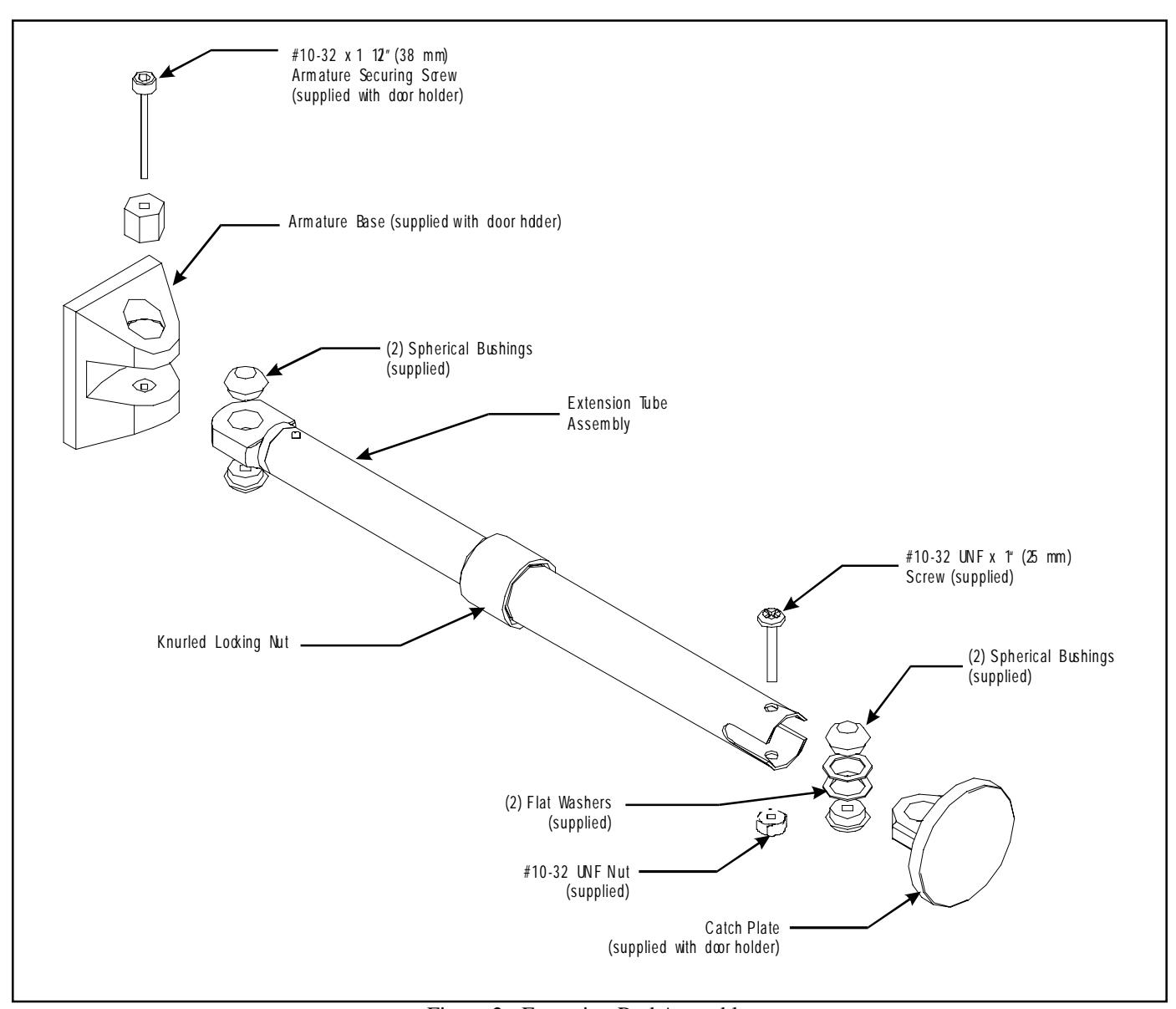
Figure 2. Extension Rod Assembly