DynaLock 2806 Series Installation Instructions
Open the original PDF document
View PDF
|
28
06 |
||||


DynaLock Corporation 705 Emmett StreetBristol, CT 06010 Ph/ 860.582.4761Fx/ 860.585.0338E-mail/ info@dynalock.com
WWW.DYNALOCK.COM
© 2010 DYNALOCK CORP. Printed in USA
Electromagnetic Door Holder Model 2806
M2806IN-01 06/2010 Page 1 of 2
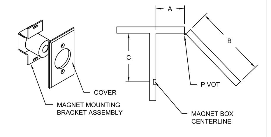
Step #1 Locations of Magnet Box:
- 1-1 Measure distance from pivot centerline to wall (Dim A)
- 1-2 Determine door width (Dim B)
- 1-3 To locate magnet box use Table below.
- 1-4 Dim C is the distance from the pivot centerline to the magnet box centerline. Result: Dim C=38 1/2" Example: Dim A=10" Dim B=42"
- 1-5 If Dim A or Dim B falls between the numbers listed in the table allow for difference. Example: Dim A=7" Dim B=36" Estimated Dim C=32 15/16"
- 1-6 If Dim A and Dim B intersect in the shaded area, DO NOT INSTALL magnet box: The degree of door opening will not permit proper alignment between armature and
- 1-7 Suggested vertical location on top rail approximately 5" from top of door.
- 1-8 Check degree of door opening shown in table and coordinate with door closers and other door hardware.
- 1-9 Total projection of door hardware must not be more than 1 7/8" on the pul side of door.
| Dim B | 28 | 30 | 32 | 34 | 36 | 38 | 40 | 42 | 44 | 46 | 48 |
|---|---|---|---|---|---|---|---|---|---|---|---|
| Dim A | Dim C Deg | Dim C Deg | Dim C Deg | Dim C Deg | Dim C Deg | Dim C Deg | Dim C Deg | Dim C Deg | Dim C Deg | Dim C Deg | Dim C Deg |
| 2 | 25 3/8 90 | 27 3/8 90 | 29 3/8 90 | 31 3/8 90 | 33 3/8 90 | 35 3/8 90 | 37 1/4 90 | 39 3/8 90 | 41 3/8 90 | 43 3/8 90 | 45 3/8 90 |
| 4 | 25 1/4 95 | 27 1/4 94 | 29 1/4 94 | 31 1/4 94 | 33 1/4 94 | 35 1/4 93 | 37 3/8 93 | 39 3/8 93 | 41 3/8 93 | 43 3/8 93 | 45 3/8 93 |
| 6 | 25 99 | 31 1/8 98 | 45 1/8 95 | ||||||||
| 8 | 26 5/8 103 | ||||||||||
| 10 | 26 1/8 107 | ||||||||||
| 12 | 25 3/8 112 | 44 1/4 103 | |||||||||
| 14 | 22 1/4 119 | 24 1/2 116 | |||||||||
| 16 | 23 1/2 121 | 25 3/4 119 | 36 3/4 111 | 43 1/8 108 | |||||||
| 18 | 24 1/2 123 | 26 7/8 121 | |||||||||
| 20 | 28 | 123 | 30 3/8 121 | 39 3/8 115 | ||||||||
| 22 | 31 1/2 123 | 33 7/8 121 | 40 5/8 116 | ||||||||
| 24 | 35 122 | 37 1/4 121 | 39 5/8 119 |
Step #2 Continued:
- 2-3 The 2 outlet box must be inserted in the wall in such a way that the center line of the outlet box coincides with the line created in 2-1.
- 2-4 The box should be installed with reinforcement to withstand a minimum 50 lb. pull.
- 2-5 The height of the outlet box must be chosen so the door armature can be installed at the same height on the door without interfering with the other door hardware.
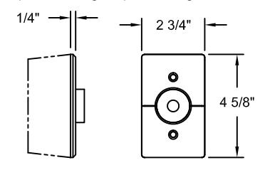
- 2-6 Install and verify the proper bracket and cover alignment.
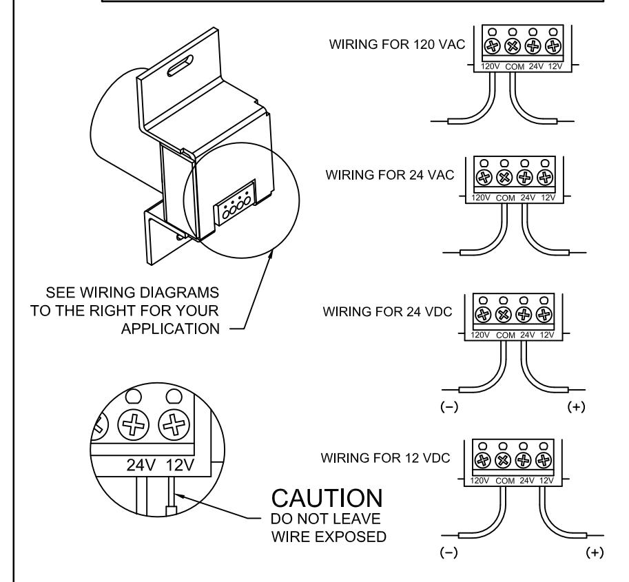
- 2-7 For detail on electrical wiring, read the specific "Electrical Data Sheet" at the end of this documentation.
IMPORTANT: Check that power voltage equals voltage labeled on back of magnet.
An outlet box should be mounted with reinforcement to withstand load from door
Step #2 Installation of Wall Magnet Box:
- 2-1 Locate on the wall the dimension Dim C by tracing a temporary vertical line at the distance Dim C (calculated in the previous step) from corner of the wall.
- 2-2 Proper electrical wire routing must be done before installing magnet box.
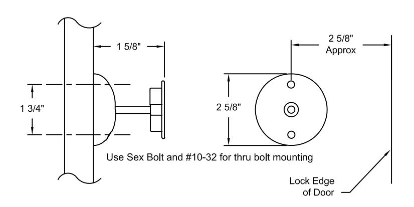
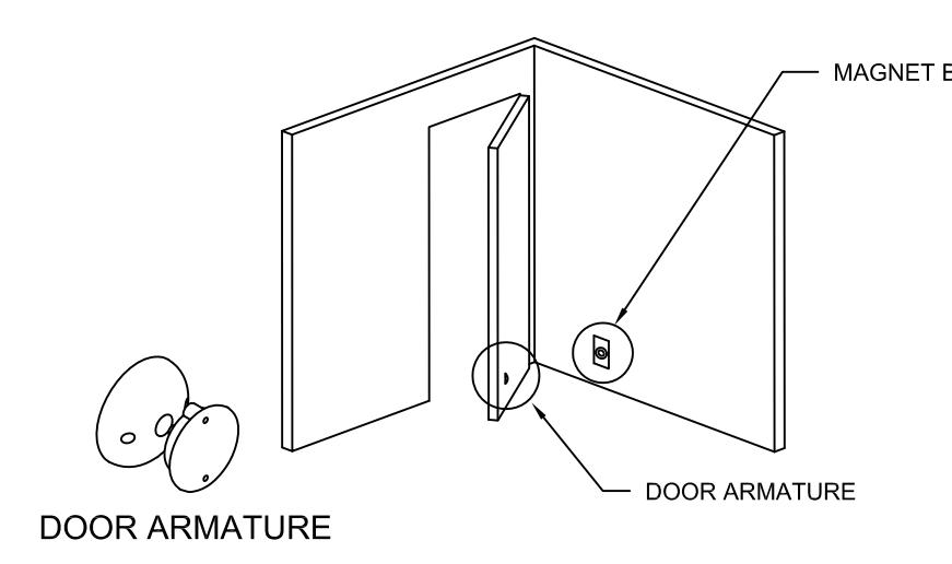
Step #3 Installation of door armature hardware:
- 3-1 With the magnet box securely fastened, aligned and energized, place and center the door armature on the surface of the magnet with the two holes of the base aligned either vertically or horizontally.
- 3-2 Gently close the door and adjust the angle of the door armature so the base lays flat against the door.
- 3-3 While keeping slight pressure on the door, mark location of door armature through the two base holes. The two marks should be 1 3/4" apart and the center line of the door armature should be approximately 2 5/8" form the lock edge of the door.
- 3-4 Depending of the mounting option that you choose:
For concealed Mounting
Drill a 1/2" deep hole where the two marks are located with a 1/16" maximum diameter drill as pilot holes for wood screws. In reinforced metal door, drill & tap for #10-32 screw
For through bolt Mounting
Drill through the door where the two marks are located with a 5/16" drill.
3-5 Mount the door armature on the door.
For concealed Mounting
Use two #10 pan head phillips wood screws or two #10-32 screws depending on type of door (See step 3-4)
OR:
For through bolt Mounting
Use two #10-32 screws with two #10-32 x 1 1/4" sex bolt.

DynaLock Corporation 705 Emmett Street Bristol, CT 06010 Ph/ 860.582.4761 Fx/ 860.585.0338 E-mail/info@dvnalock.com
WWW.DYNALOCK.COM
Electromagnetic Door Holder Model 2806