DynaLock 2801 Series Installation Instructions
Open the original PDF document
View PDF
|
28
01 |
|||

DynaLock Corporation 705 Emmett StreetBristol, CT 06010 Ph/ 860.582.4761Fx/ 860.585.0338E-mail/ info@dynalock.com
WWW.DYNALOCK.COM
© 2010 DYNALOCK CORP. Printed in USA
Electromagnetic Door Holder Model 2801
M2801IN-01 06/2010 Page 1 of 2
Step #1 Locations of Magnet Box:
-
1-1 Find the following:
- 1. Pivot point of door
- 2. Door Width (Inches)
- 3. Maximum degree of door opening permitted by door opener.
- (Note trim and partition clearance needed)
- 1-2 Determine arc length by subtracting 5 5/8" from width of door.
Example: If door is 36"
Width of door 36" Subtract 5 5/8"
Arc Length = 30 3/8"
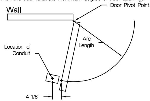
1-3 Determine degree of desired door opening with consideration for partition Allow 6" Dia clearance around conduit and any partition for 2600 Series assembly
(See drawing below)
(Conduit should be located on an arc and 4 1/8" from the pull side of door, when the door is at the maximum degree of door opening)
Step #2 Installation of Wall Magnet Box:
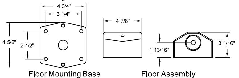
- 2-1 Locate magnet assembly on pull side of door near bottom rail Approximately 6" from lock edge using floor mounting base as template. See illustration below.
- 2-2 Using the marked locations, drill mounting holes in floor for 5/8"
- 2-3 Mount magnet base to floor using 5/8" anchors and screws.
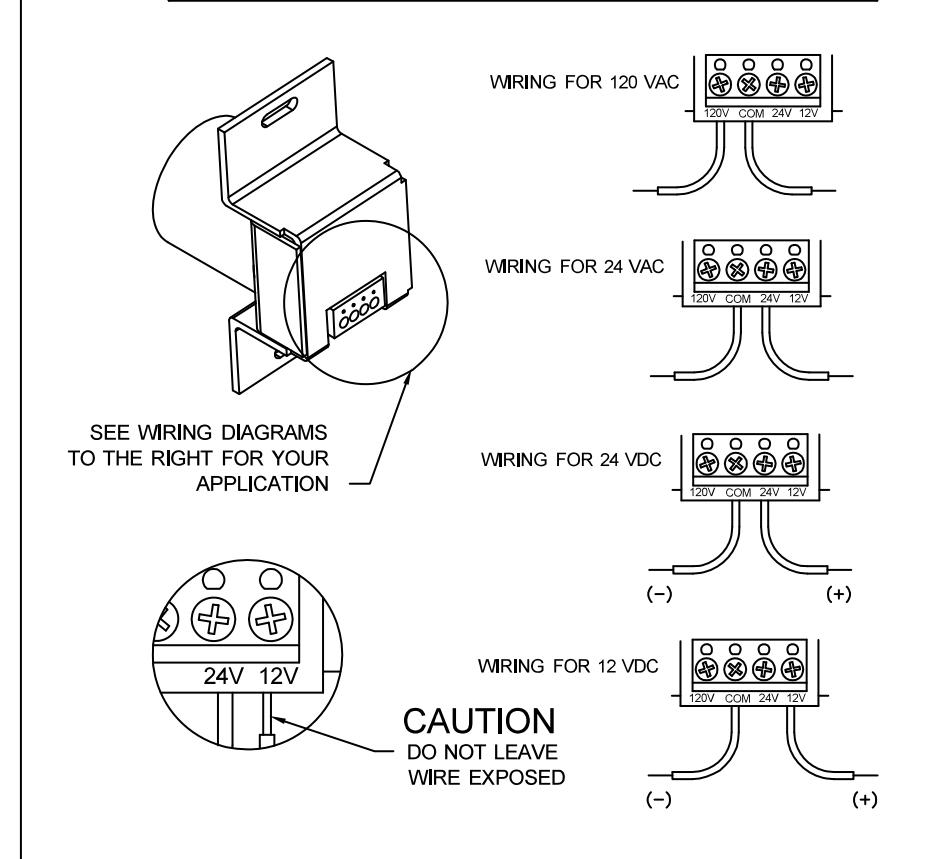
- 2-4 For detail on electrical wiring, read the specific "Electrical Data Sheet" at the end of this documentation.
- IMPORTANT: Check that power voltage equals voltage labeled on back of magnet
Step #2 Continued:
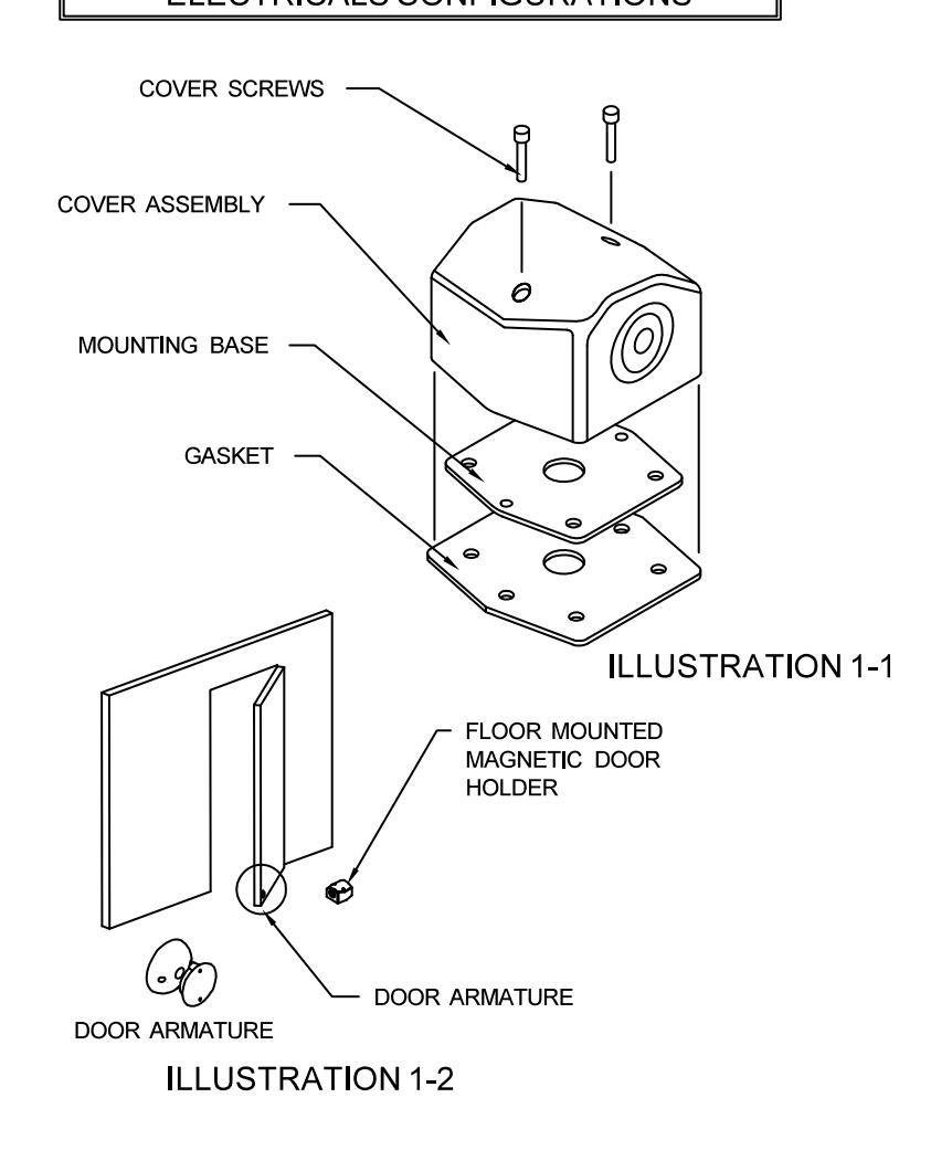
- 2-5 Position cover gasket on base.
- 2-6 Assemble cover to base plate using provided mounting screws.
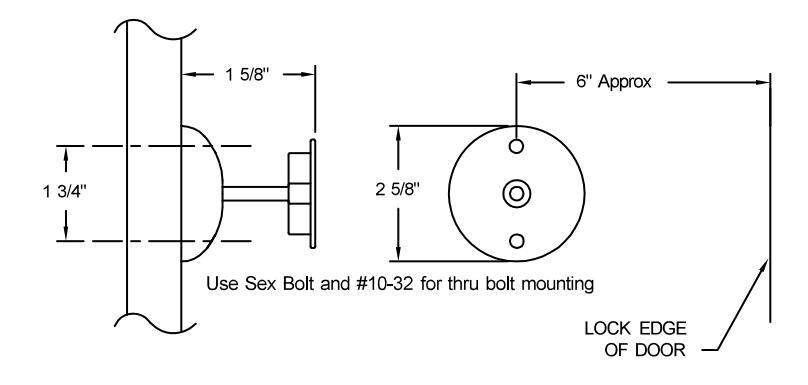
Step #3 Installation of door armature hardware:
- 3-1 With the magnet box securely fastened, aligned and energized, place and center the door armature on the surface of the magnet with the two holes of the base aligned either vertically or horizontally.
- 3-2 Gently close the door and adjust the angle of the door armature so the base lays flat against the door.
- 3-3 While keeping slight pressure on the door, mark location of door armature through the two base holes. The two marks should be 1 3/4" apart and the center line of the door armature should be approximately 6" form the lock edge of the door.
- 3-4 Depending of the mounting option that you choose:
For concealed Mounting
Drill a 1/2" deep hole where the two marks are located with a 1/16" maximum diameter drill as pilot holes for wood screws. In reinforced metal door, drill & tap for #10-32 screw
OR:
For through bolt Mounting
Drill through the door where the two marks are located with a 5/16" drill.
3-5 Mount the door armature on the door:
For concealed Mounting
Use two #10 pan head phillips wood screws or two #10-32 screws depending on type of door (See step 3-4)
OR:
For through bolt Mounting
Use two #10-32 screws with two #10-32 x 1 1/4" sex bolt.

DynaLock Corporation 705 Emmett Street Bristol, CT 06010
Ph/ 860.582.4761 Fx/ 860.585.0338 E-mail/ info@dynalock.com
WWW.DYNALOCK.COM
Electromagnetic Door Holder Model 2801
M2801IN-01 06/2010 Page 2 of 2