DynaLock 2585 Series Installation Instructions
Open the original PDF document
View PDF

MODEL #2585 ELECTROMAGNETIC LOCK INSTALLATION INSTRUCTIONS
PLEASE READ BEFORE INSTALLATION
Familiarize yourself with the door and frame conditions prior to installation. The lock must rigidly mount to the underside of the frame header. The armature is designed to pivot slightly to compensate for reasonable misalignment.
Armature mounting hardware is supplied for a standard 1-3/4" thick door. For thicker doors order the following special armature hardware kits:
Part #300687 for 2" thick doors. Part #300688 for 2-1/4" thick doors.
HANDLING
The Electromagnetic lock and armature are ruggedly constructed and designed to provide years of trouble-free service. Care must be taken during installation and use to keep the lock face and armature face free from dirt, rust, burrs, paint, or any other obstruction which may interfere with the lock and armature making good contact.
MAINTENANCE
The lock assembly and door armature have been plated for maximum corrosion resistance. To ensure peak performance clean the lock and armature faces with a mild detergent and a clean, soft cloth, then apply a light coat of WD40 to protect these surfaces. This need only be done when dirt build-up is noticed.
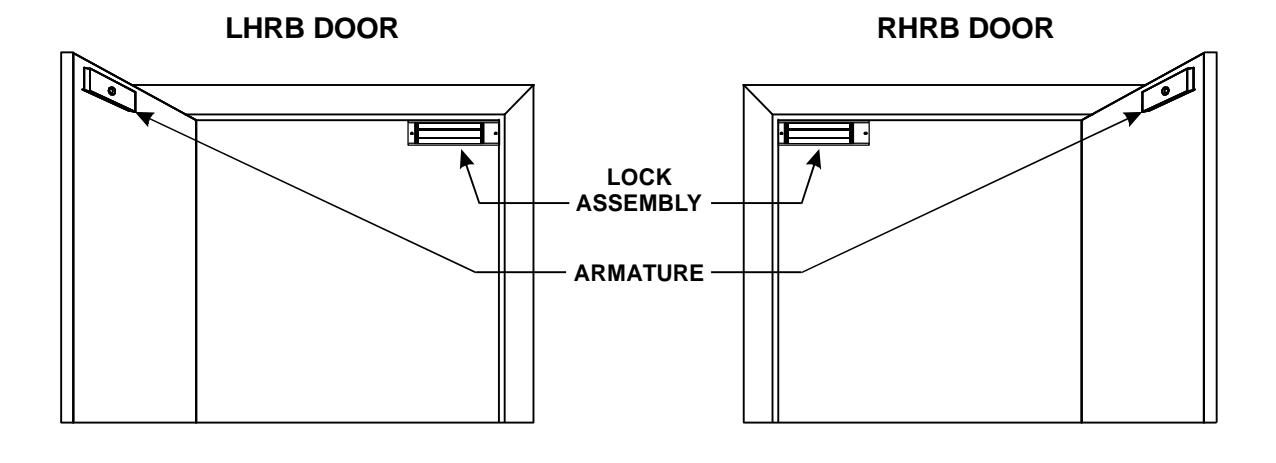
GENERAL MOUNTING INFORMATION
The illustrations below depict typical installations of the Model #2585 Lock on single-outswing doors. The lock assembly must be surface mounted to the underside of the frame header with the armature affixed to the inside face of the door as shown.
MOUNTING PREPARATION
SURVEY THE INSTALLATION 1.
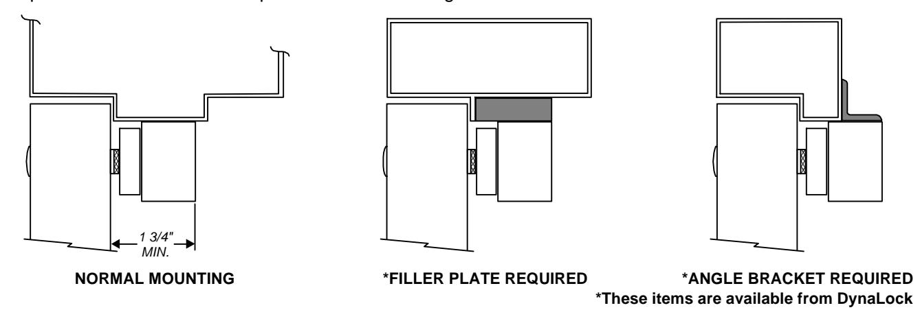
Inspect the door frame and determine if an angle bracket or filler plate will be required for installation. The lock will require a 1-3/4" wide header stop for a suitable mounting surface.
PREPARE THE FRAME FOR MOUNTING THE LOCK ASSEMBLY 2.
Determine the hand of the door - LHRB or RHRB and look at the template edge for proper positioning of the template.
- A. Fold the template on the dotted line to form a 90 degree angle.
- B. With the door in the closed and latched positon, place the template against the header and door with one edge of the template against the vertical lock jamb and tape in place.
- C. Transfer all hole locations to both the door and header with a center punch.
- D. Remove the template from the door.
PREPARE THE DOOR FOR ARMATURE MOUNTING 3.
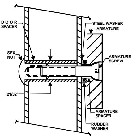
From the three illustrations below, select the one that resembles your door type and follow the instructions for drilling the armature mounting screw hole. Drill two (2) 1/4" dia. holes 9/16" deep at the anti-spin pin locations ( See Template ).
GLASS AND ALUMINUM OR HOLLOW METAL DOOR SOLID CORE DOOR REINFORCED DOOR
Drill an 11/32" diameter hole through door. From sex nut side only enlarge the 11/32" hole to 21/32" diameter.
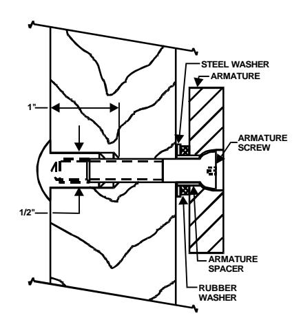
Drill an 11/32" diameter hole through door. From sex nut side only drill 1/2" diameter hole to 1" depth.
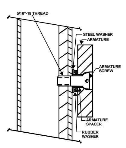
Drill an 17/64" diameter hole and tap for 5/16"-18 thread.
MOUNT THE ARMATURE TO THE DOOR 4.
Failure to properly secure the armature to the door could result in serious injury or possible security breach. Locate the two 3/16" dia.anti-spin pins from the hardware kit. Place the armature face-down on a soft surface ( i.e. the shipping carton ) and drive the anti-spin pins into the holes provided. Refer to Note #3 illustrations to select the correct mounting hardware and mount the armature. Firmly tighten the armature mounting screw with a 3/16" hex wrench.
PREPARE THE HEADER FOR LOCK MOUNTING 5.
Refer to the Template and drill four 1/8" dia. mounting holes and one 9/16" diameter wiring hole where shown.
MOUNT THE LOCK TO THE HEADER 6.
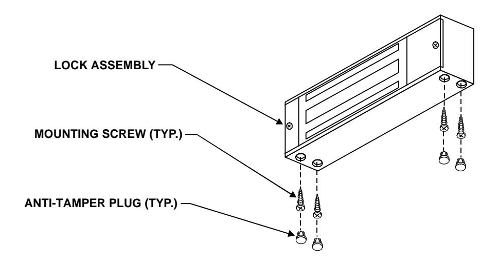
Remove the Access and End Covers from the lock assembly (see Exploded View - page 4). Using the four #10 x 1" phillips flat head self-tapping screws provided secure the lock assembly to the header. Firmly tighten the screws with a #2 phillips head screw driver. Locate the four anti-tamper plugs and install over the mounting screw holes with a soft mallet. Replace the Access and End Covers.
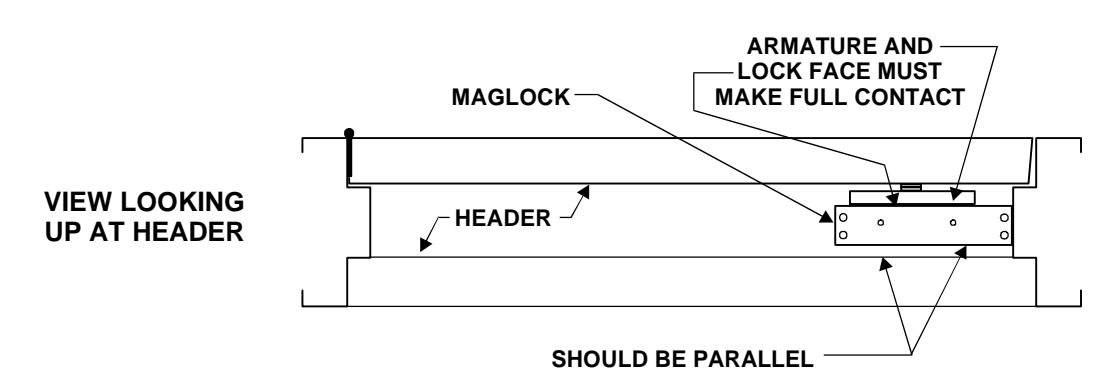
CHECK LOCK AND ARMATURE FOR PROPER ALIGNMENT 7.
Close and latch the door. Verify that the lock face and armature are making full contact over the entire armature length. The armature must be aligned to cover the full active face of the lock, represented by the three parallel bars visible from the front. Should the armaturebe offset holding force will be reduced significantly. Make any corrections as necessary.
COMPLETION 8.
The mechanical installation is now complete. Refer to separate wiring instructions for electrical hook-up information. (Refer to Dwg. #900304)
2585 BILL OF MATERIAL
- 1 Mounting Instructions
- 1 Wiring Instructions
- 1 Electromagnetic Lock
-
1 Hardware Kit consisting of:
- 4 #10 x 1" Phillips Flat Head self-tapping screws
- 4 Anti-tamper Plugs
- 1 1/4" long Armature Spacer
- 1 1/8" thick Rubber Washer
- 1 1/16" thick Steel Washer
- 2 3/16" x 3/4" long Anti-spin Pins
- 1 Template
- 1 Armature
-
1 Armature Bolt assembly consisting of:
- 1 5/16-18 x 2" Hex flat head machine screw.
- 1 5/16-18 Sex Nut
- 1 1-11/16" long Door Spacer
TOOLS REQUIRED
- 1 Electric Drill
- 1 #2 Phillips Head Screw Driver
- 1 Soft-faced Mallet
- 1 3/16" Hex Wrench
- 1 11/32" Drill Bit
- 1 21/32" Drill Bit
- 1 9/16" Drill Bit
- 1 1/8" Drill Bit
- 1 17/64" Drill Bit
- 1 1/4" Drill Bit
- 1 Hammer
- 1 Center Punch
Pencil & Tape
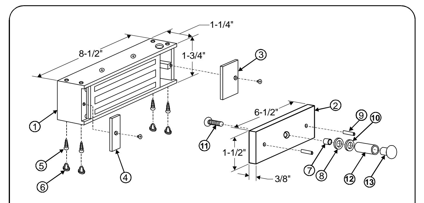
DESCRIPTION
- 1. Magnet Assembly
- 2. Armature
- 3. Access Cover
- 4. End Cover
- 5. Mounting Screw
- 6. Anti-tamper Plug
- 7. Armature Spacer
- 8. Rubber Washer
- 9. Anti-spin Pin
- 10. Steel Washer
- 11. Armature Bolt
- 12. Door Spacer
- 13. Sex Nut
PART NUMBER
Consult Factory #300141 #300945 #300944
Hardware Kit Part #300762
2585 EXPLODED VIEW