DynaLock 2268-TJ20 Series Installation Instructions
Open the original PDF document
View PDF

INSTALLATION DESCRIPTION
The Series 2268-TJ20 is a 1200 pound holding force top jamb mounted electromagnetic lock designed to secure a double in-swinging pair of doors. The lock requires both installation procedures as described herein and in the separate wiring instructions included.
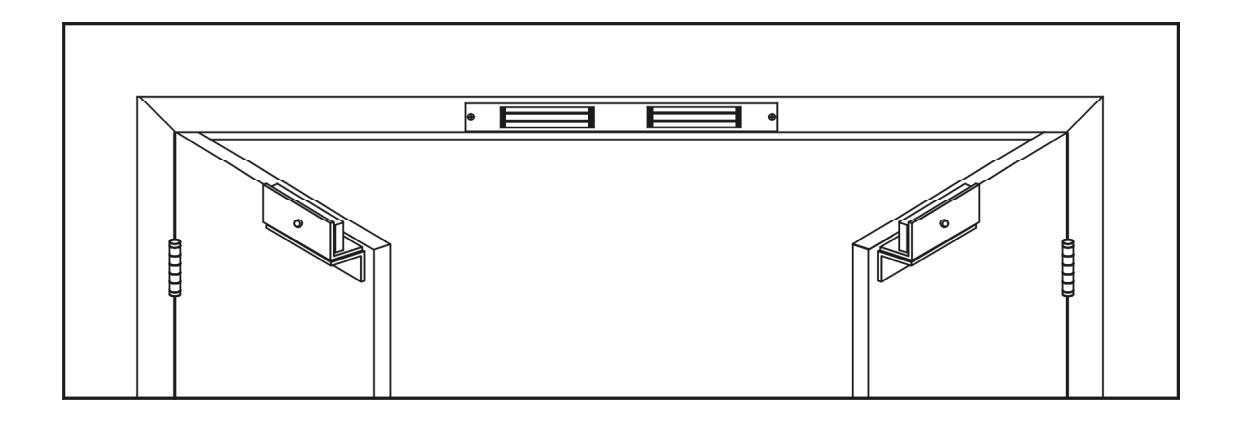
Typical installations of the lock on double-inswing doors:
HANDLING
Care must be taken that the lock face and armature face are kept free of dirt, rust, paint, or any other obstruction which may interfere with the lock and armature making good contact. These faces may be cleaned with a nonabrasive pad and wiped with an oil dampened cloth.
MECHANICAL INSTALLATION
Familiarize yourself with the door and frame conditions. The lock must mount rigidly to the face of the door frame header. The door mounted armatures are supplied with adjustable mounting brackets and hardware that allows them to pivot slightly to compensate for reasonable misalignment.
NOTE: If this lock is supplied with the DSM2 feature be certain to mount the armatures so that the DSM block (magnet) extensions are aligned with the reed switches in the lock assembly.
ELECTRICAL INSTALLATION
After mechanical installation is complete the locks needs to be wired to a 12 or 24 VDC power source (AC requires rectifier option). Once low voltage power is supplied the unit is fully operational. All other wiring is for selected options. Refer to the separate wiring instructions included for further information.

Ph/ 860.582.4761 ? Fx/ 860.585.0338
SERIES 2268-TJ20 ELECTROMAGNETIC LOCK INSTALLATION INSTRUCTIONS
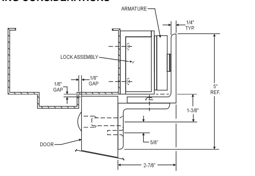
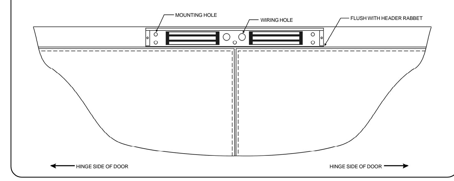
MOUNTING CONSIDERATIONS
- Individual door and frame conditions may vary. Dimensions shown at right are for a typical hollow metal door and frame. 1.
- The lock assembly should be mounted in the center of the opening for maximum performance. Verify that there is proper clearance for the lock assembly at the planned mounting location. 2.
- Electrical wiring for the locks must be routed through the back of the unit, through a hole drilled in the face of the frame header. 3.
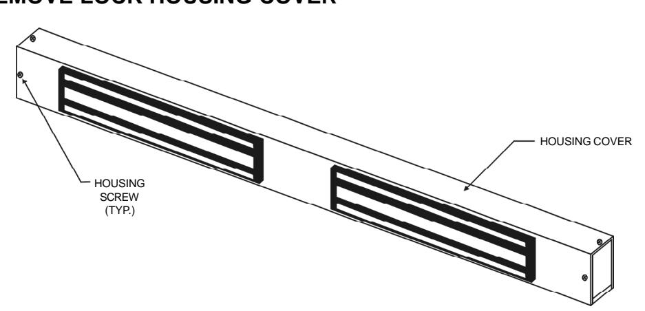
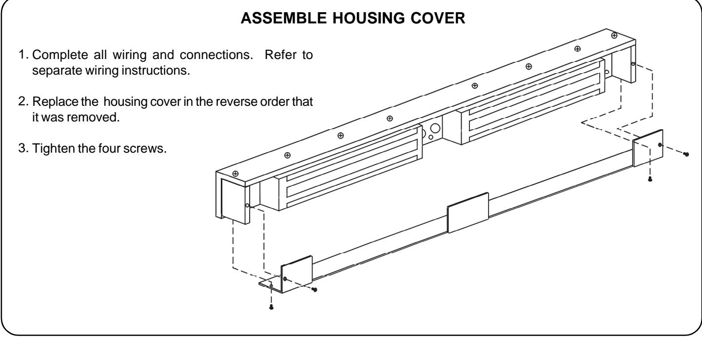
REMOVE LOCK HOUSING COVER
- 1. Remove two front and two bottom housing screws.
- 2. Remove housing cover.
Standing at the "pull" side of the door, position the lock assembly on the face of the frame header as shown on the following page. Using prep drawing #301199, locate and mark the centers of the five mounting holes and either of the wiring holes. 1.
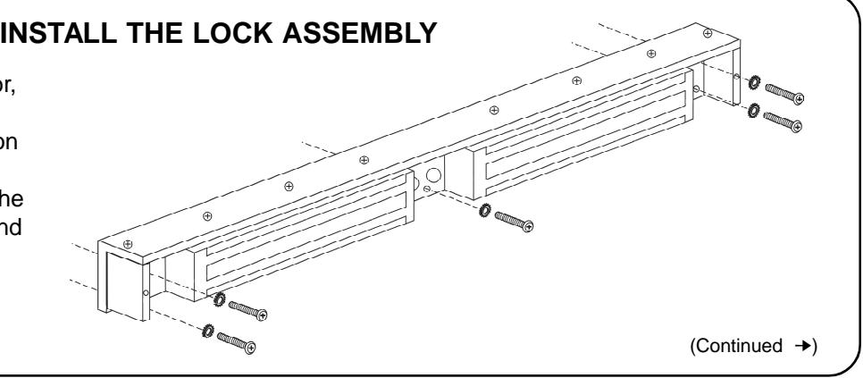

Drill the marked holes in the face of the frame header. 2.
Ph/ 860.582.4761 ? Fx/ 860.585.0338
- a. Five (5) 3/16" diameter holes for #14 x 1" pan head sheet metal screws (use for wood or hollow metal frames) OR
- Five (5) 13/64" diameter holes and tap for 1/4-20 x 1" machine screws (use for reinforced metal frames)
- b. One (1) hole for wiring. Openings are 3/4" remember to protect wire from sharp edges.
- Attach the lock assembly to the frame header using the appropriate screws and 1/4" external tooth lock washers. 3.
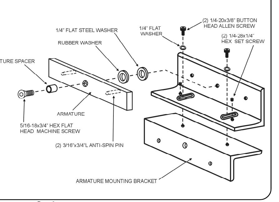
ASSEMBLE THE ARMATURE MOUNTING BRACKETS
- 1. Locate the armature mounting hardware from the hardware kit and attach the armature to the top armature mounting bracket as shown. Firmly tighten the armature mounting screw with the supplied 3/16" hex wrench.
- 2. Assemble the top and bottom armature mounting brackets together using the fasteners shown. Do not completely tighten the low cap allen screws at this time. The set screws can be threaded but do not tighten.
- 3. Repeat for second bracket assembly.
Failure to properly secure the armature to the bracket could result in serious injury or possible security breach.

INSTALL THE ARMATURE MOUNTING BRACKETS
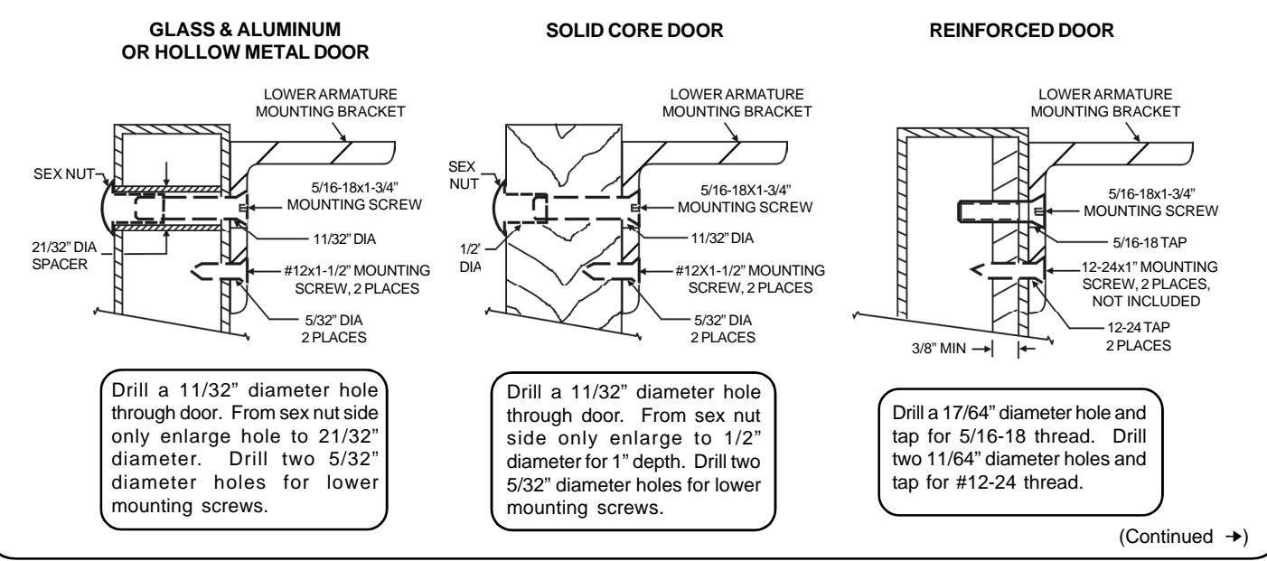
Use the figures below to identify and mark the locations of the armature mounting bracket screw holes on the door. Refer to door and frame prep drawing #xxxxx for further information. 1.
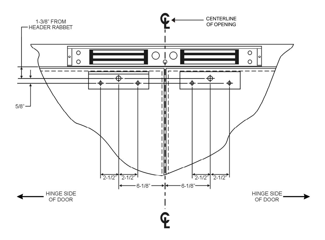
2. From the illustrations below select the one that resembles your door type and follow the instructions for drilling the three (3) armature mounting bracket screw holes.

Ph/ 860.582.4761 ? Fx/ 860.585.0338
SERIES 2268-TJ20 ELECTROMAGNETIC LOCK INSTALLATION INSTRUCTIONS
Mount the armature and mounting bracket assemblies to the doors using the appropriate hardware for your door types. Firmly tighten the mounting screws with a 3/16" hex wrench and phillips screwdriver. 3.
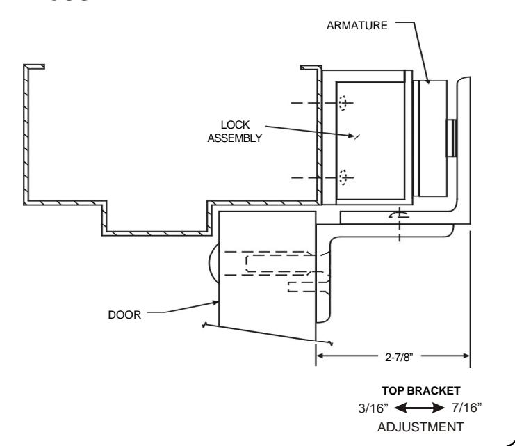
ARMATURE ADJUSTMENT
- On the first door, loosen the button head allen screws just enough as to allow the top armature bracket assembly to move in and out freely. 1.
- Close and latch the door. The mating surfaces of the lock and armature should fully contact each other. If necessary slide the armature in or out to ensure full contact is made with the lock while still allowing the door to properly close and latch. 2.
- When the desired adjustment is achieved slowly open the door, taking care to maintain the position of the armature. Firmly tighten the button head allen screws with a 3/16" hex wrench. 3.
- Tighten the two set screws with a 1/8" hex wrench. 4.
- Repeat for other door. 5.

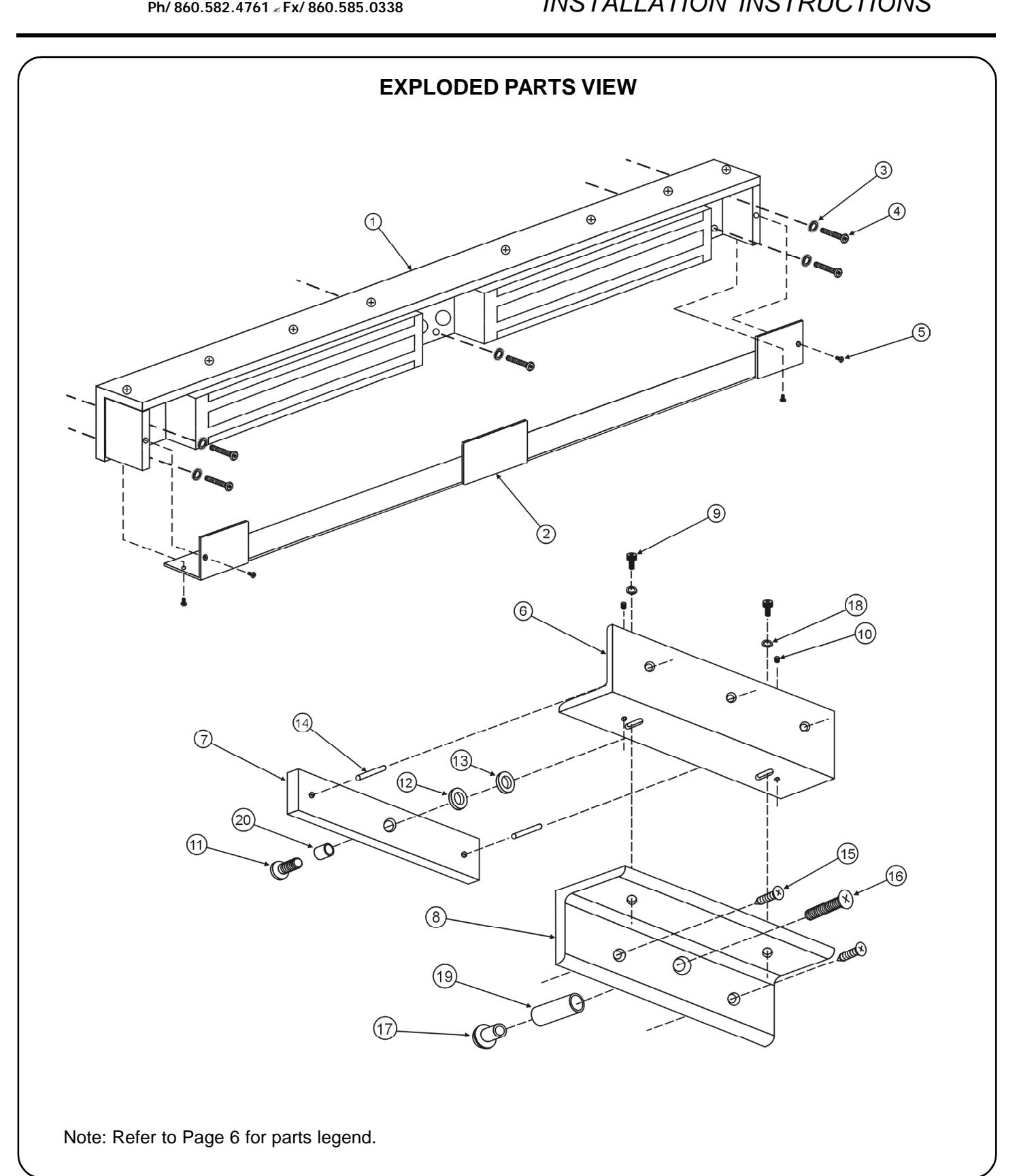
EXPLODED PARTS VIEW LEGEND
Note: Refer to Page 7 for parts locations.
| ITEM | DESCRIPTION | PART NO. | ITEM | DESCRIPTION | PART NO. |
| 1 | Lock Assembly | 301191 | 11 | 5/16-18x3/4" Armature Screw | 300588 |
| 2 | Lock Housing Cover | 301192 | 12 | Rubber Washer | 300003 |
| 3 | 1/4" External Tooth Washer | 300971 | 13 | 1/4" Flat Steel Washer | 300550 |
| 4 | 1/4-20x1" Machine Screw** | 300972 | 14 | 3/16"x3/4" Anti-spin Pin | 300586 |
| 5 | 8-32x3/8" Housing Cover Screw | 300608 | 15 | #12x1-1/2" Sheet Metal Screw | 300600 |
| 6 | Upper Armature Mtg. Bracket | 301183 | 16 | 5/16-18x1-3/4" Machine Screw | 300589 |
| 7 | Armature | 300968 | 17 | Sex Nut | 300004 |
| 8 | Lower Armature Mtg. Bracket | 301184 | 18 | 1/4" Flat Steel Washer | 300550 |
| 9 | 1/4-20x3/8" Button Head Screw | 301197 | 19 | Door Spacer | 300001 |
| 10 | 1/4-28x1/4" Set Screw | 300604 | 20 | Armature Spacer | 300002 |
| 11 | 5/16-18x3/4" Armature Screw | 300588 |
| 12 | Rubber Washer | 300003 |
| 13 | 1/4" Flat Steel Washer | 300550 |
| 14 | 3/16"x3/4" Anti-spin Pin | 300586 |
| 15 | #12x1-1/2" Sheet Metal Screw | 300600 |
| 16 | 5/16-18x1-3/4" Machine Screw | 300589 |
| 17 | Sex Nut | 300004 |
| 18 | 1/4" Flat Steel Washer | 300550 |
| 19 | Door Spacer | 300001 |
| 20 | Armature Spacer | 300002 |
** #14 x 1" Sheet Metal Screws can also be used (PN# 300973)