DynaLock 2268 Series Installation Instructions
Open the original PDF document
View PDFPhone: (860)582-4761 Fax: (860)585-0338
SERIES 2268 ELECTROMAGNETIC LOCK WIRING INSTRUCTIONS
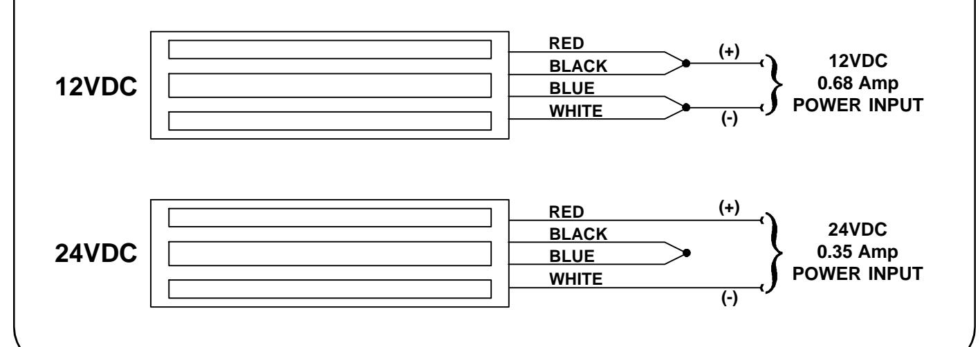
CONFIGURE LOCK OPERATING VOLTAGE
The 2268 Series maglock may be configured to operate on 12VDC or 24VDC input power. Connect the four coil wires as shown below, to match the power input. To operate the lock on low voltage AC input power, the optional rectifier (RC option) must be conected to the lock. Refer to the RC Option instructions for further information.
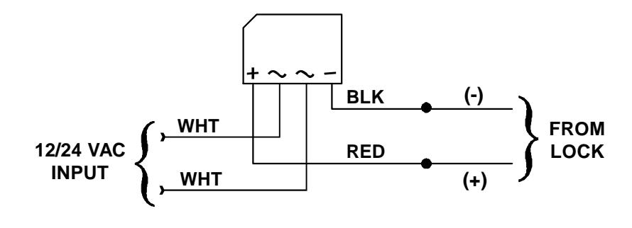
RECTIFIER (RC) OPTION WIRING FOR 12/24VAC OPERATION
Connect the RC Option pre-wired rectifier to the lock and the power source as shown to permit the 2268 to operate on 12 or 24VAC input power.
ANTI-TAMPER SWITCH (ATS) OPTION WIRING
The ATS Anti-Tamper Switch Option provides a SPDT set of dry contacts to signal the physical position of the access cover for remote monitoring purposes (i.e. - access cover 'open' or access cover 'closed'). Typical system connections are shown below.
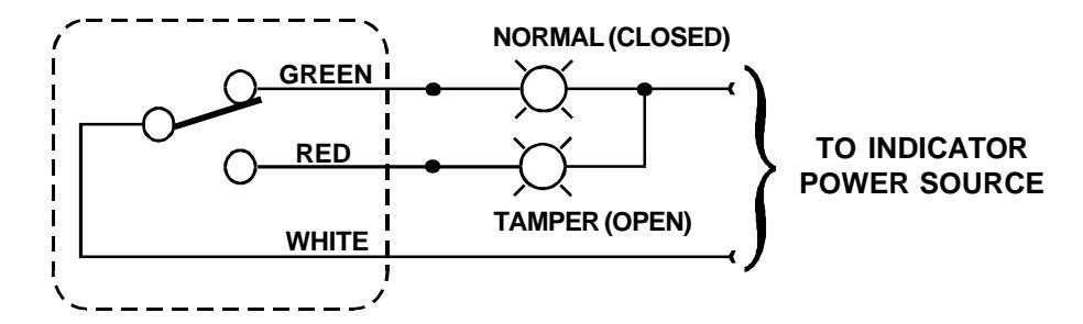
NOTE: Indicators are not included.
ATS contact rating - 0.5 Amp @ 24VAC/VDC
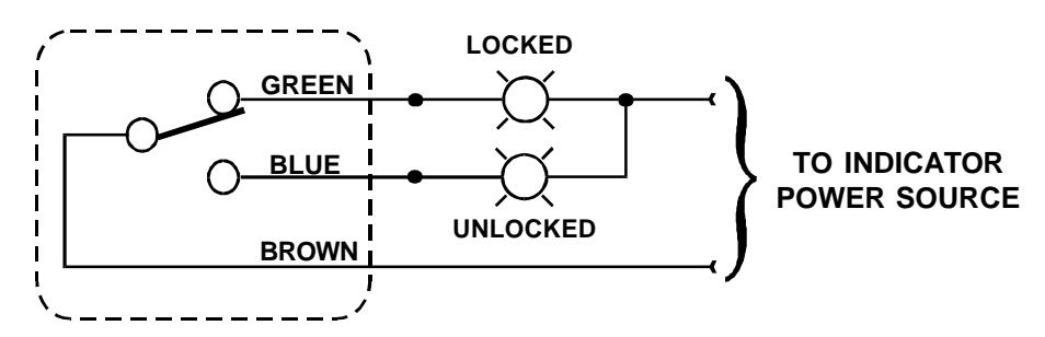
DOOR STATUS SWITCH (DSM) OPTION WIRING
The DSM Door Status Switch Option provides a SPDT set of dry contacts to signal the physical position of the door for remote monitoring purposes (i.e. - door 'open' or door 'closed'). Typical system connections are shown below.
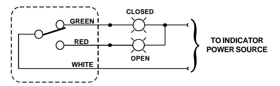
NOTE: Indicators are not included.
DSM contact rating - 0.5 Amp @ 24VAC/VDC
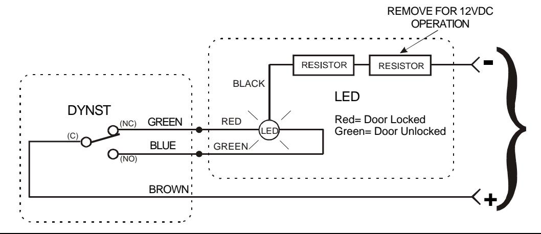
DYNASTAT FORCE SENSOR (DYNST) OPTION WIRING
The DYNST Dynastat Force Sensor Option provides a SPDT set of dry contacts to signal whether an efficient magnetic bond has occured between the mating surfaces of the magnetic lock and armature for remote monitoring purposes (i.e. - door 'locked' or door 'unlocked'). Typical system connections are shown below.
NOTE: Indicators are not included.
Dynastat contact rating - 0.25 Amp @ 24VAC/VDC
LED OPTION
The Bi-Color LED is used in conjunction with the Dynastat (DYNST) option to display lock status in two colors - red or green and is pre-configured to operate on 24VDC. For 12VDC operation remove the outer resistor from the black wire. Connect the LED to the DYNST as shown below.
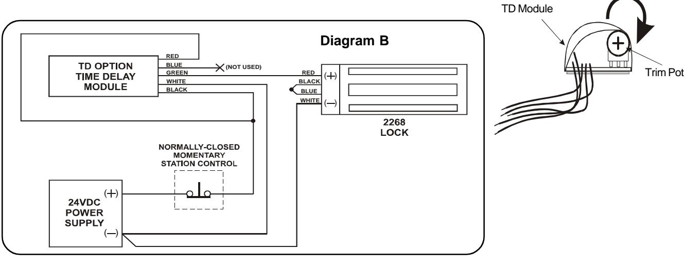
TIME DELAY (TD) OPTION WIRING
The TD time delay option provides adjustable time delayed relocking. This is a field installed device and wired per the following wiring diagrams. Diagram " A " is wired for 12VDC while diagram " B " is shown wired for 24VDC.
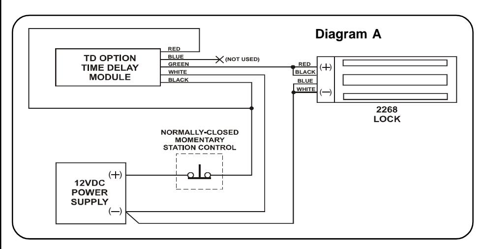
Time Delay Adjustment
Rotate trim pot clockwise to increase time delay. Range = 0-60 sec.
2268 GENERAL SPECIFICATIONS
OPERATING VOLTAGES: 12 or 24VDC Field Selectable
12 or 24VAC With RC Rectifier Option
POWER CONSUMPTION: 0.68 Amp @ 12 Volts
0.35 Amp @ 24 Volts
SURGE SUPPRESSION: Built-in
HOLDING FORCE: 1200 Lbs.
COIL RESISTANCE: 34.1 Ohms (+-10%) Black-White / Red-Blue
TERMINATIONS: 12" Long Color-Coded Wire Leads
FOR PRODUCT SUPPORT AND PARTS ORDERING INFORMATION CONTACT:
DynaLock Corp. 705 Emmett Street Bristol, CT 06010
Bus: (877) 396-2562 Toll-Free USA
(860) 582-4761 Fax: (860) 585-0338
DYNALOCK ON THE INTERNET:
E-mail: info @ dynalock.com Website: www.dynalock.com

GWXT Auxiliary Lock