DynaLock 2013 Installation Manual
Open the original PDF document
View PDF

Phone:(860) 582-4761 Fax:(860) 585-0338
SERIES 2013 ELECTROMAGNETIC GATELOCK INSTALLATION INSTRUCTIONS
PLEASE READ BEFORE INSTALLATION
Familiarize yourself with the gate and post conditions prior to installation. The lock must rigidly mount to the gate post. The armature is designed to pivot slightly to compensate for reasonable misalignment.
. Due to the wide diversity of gate designs custom mounting brackets may be necessary to facilitate the installation. A DynaLock universal Gate Lock Bracket ("GLB" Option) is available to accomodate the majority of gate applications and may be purchased separately.
The Electromagnetic lock and armature are ruggedly constructed and designed to provide years of trouble-free service. Care must be taken during installation and use to keep the lock face and armature face free from dirt, rust, burrs, paint, or any other obstruction which may interfere with the lock and armature making good contact.
HANDLING MAINTENANCE
The lock assembly and gate armature have been plated for maximum corrosion resistance. To ensure peak performance clean the lock and armature faces with a mild detergent and a clean, soft cloth, then apply a light coat of WD40 to lubricate and protect these surfaces. This need only be done when dirt build-up is noticed.
GENERAL MOUNTING INFORMATION
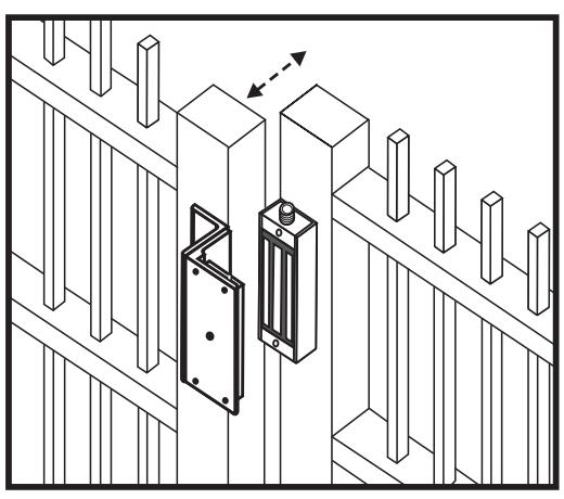
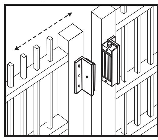
SWING GATE SLIDE GATE
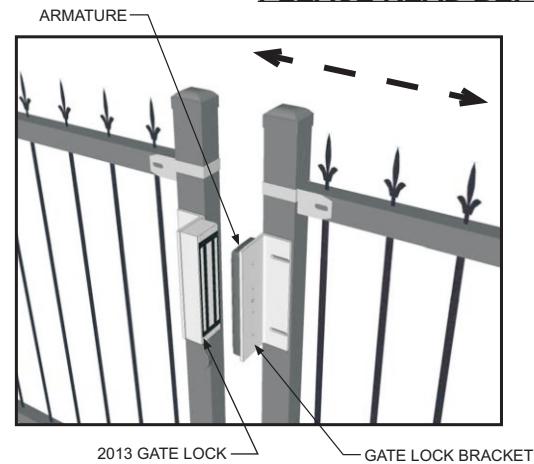
Typical installation depicting the #2013 lock mounted to the vertical gate post. The armature is mounted to the gate using the adjustable Gate Lock Bracket ("GLB" Option), available from DynaLock.
Typical installation depicting the use of "L" brackets custom-fabricated to suit the gate. The #2013 lock is mounted to the vertical gate post. The armature is mounted to the leading edge of the gate.

SERIES 2013 ELECTROMAGNETIC GATELOCK INSTALLATION INSTRUCTIONS
MOUNTING PREPARATION
SURVEYTHE INSTALLATION 1.
Inspect the gate and determine if supplemental brackets and/or special mounting hardware will be required for installation ( refer to page 1 "General Mounting Information" ). If you are using the optional Dynalock Gate Lock Bracket refer to the instructions furnished with the bracket for specific installation information. Fabricate/procure custom bracket(s), hardware, and/or attachments as necessary.
PREPARE THE GATE POST FOR MOUNTING THE GATE LOCK ASSEMBLY 2.
Determine the desired location for mounting the 2013 Gate Lock assembly on the gate post. Orient the end of the lock with the 3/4" threaded conduit fitting relative to the location of electrical hook-up wiring.
If you are mounting the lock assembly directly to the post, locate, mark, and drill four (4) 9/64" dia. mounting screw holes as per Fig. "A" on page 3. If using an intermediate bracket to affix the lock assembly to the post, prep the mounting screw holes accordingly.
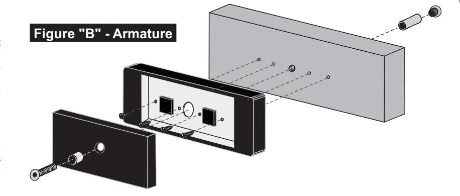
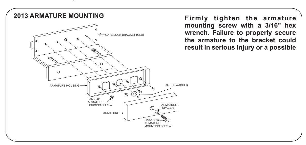
MOUNTING THE ARMATURE 3.
Attach the armature housing to the gate using two (2) #8x1" sheet metal screws or drill and tap for 8- 32x3/8" machine screws. Follow hole spacing dimensions shown in Figure B of this manual. Refer to the illustration below to select the correct mounting hardware and mount the armature. Failure to propery secure the armature to the gate could result in serious injury or possible security breach.
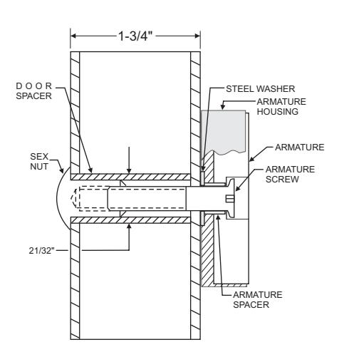
HOLLOW TUBE GATE
Drill an 11/32" diameter hole through gate. From sex nut side only enlarge the 11/32" hole to 21/32" diameter.
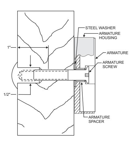
SOLID CORE GATE
Drill an 11/32" diameter hole through gate. From sex nut side only drill 1/2" diameter hole to 1" depth.
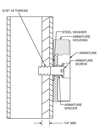
REINFORCED TUBE GATE
Drill an 17/64" diameter hole and tap for 5/16"-18 thread.

705 Emmett Street Bristol, CT 06011-2728 Phone:(860) 582-4761 Fax:(860) 585-0338
SERIES 2013 ELECTROMAGNETIC GATELOCK INSTALLATION INSTRUCTIONS
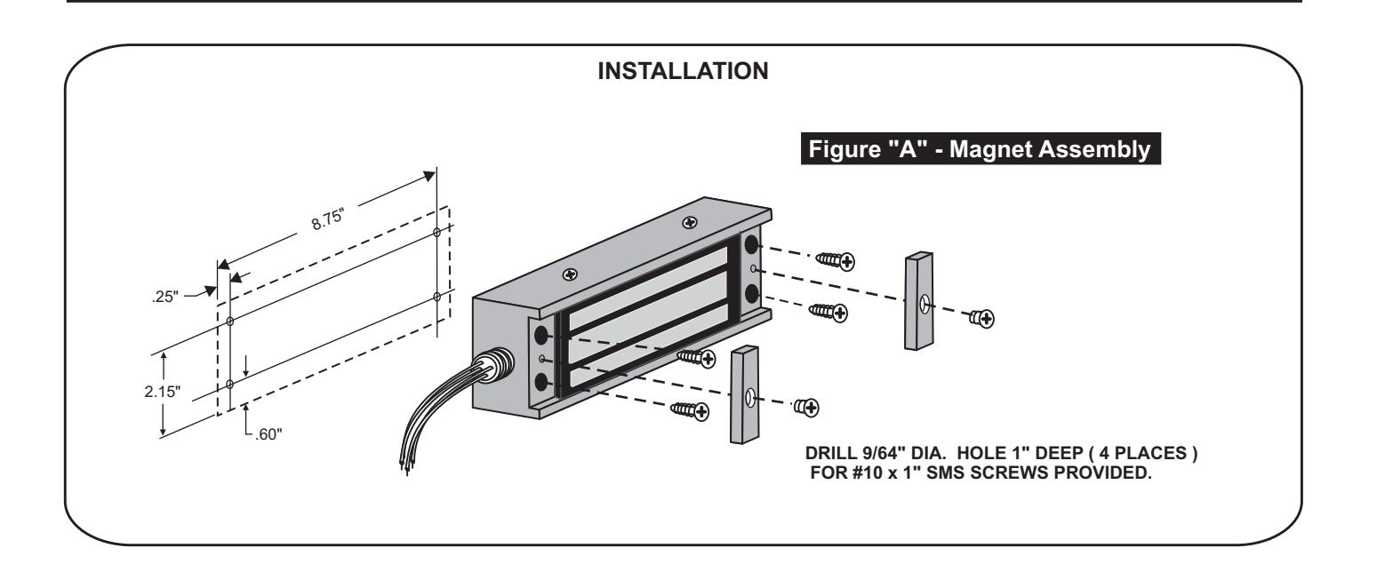
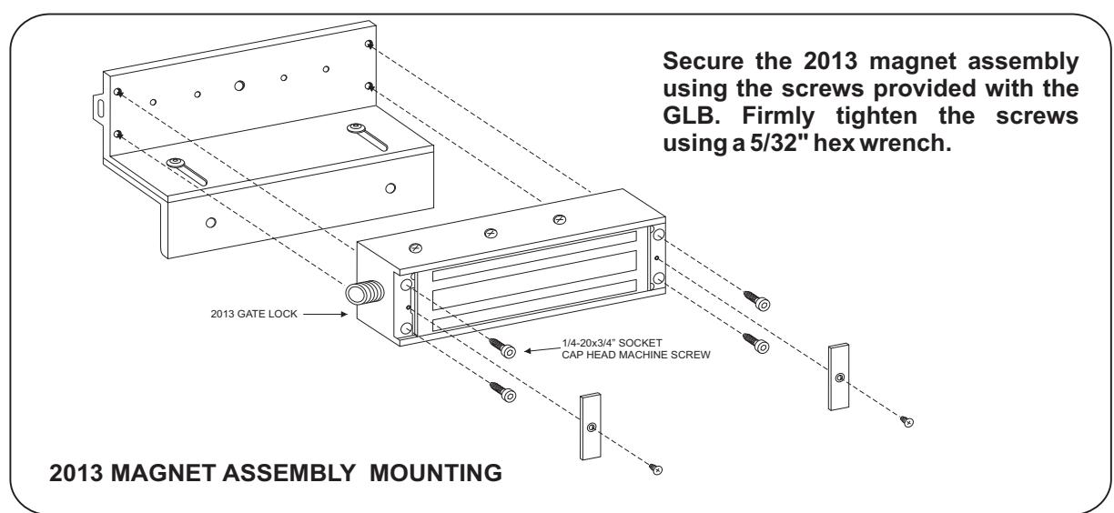
5. MOUNTING THE MAGNET
Using a phillips head screw driver mount the magnet assembly to the gate with the four #10 x 1" self-tapping screws provided. Place the end covers on and screw them in with the #8-32x1/4" phillips flat head screw.
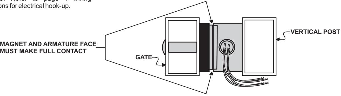
VERIFYPROPER ALIGNMENT 6.
Close the gate and verify the lock face and armature are making full contact for the entire armature length. Make corrective adjustments as necessary.
COMPLETION 7.
The mechanical installation is now complete. Refer to page 4 wiring instructions for electrical hook-up.
TOP VIEW OF 2013 GATE LOCK ASSEMBLY FOR A TYPICAL SLIDING GATE

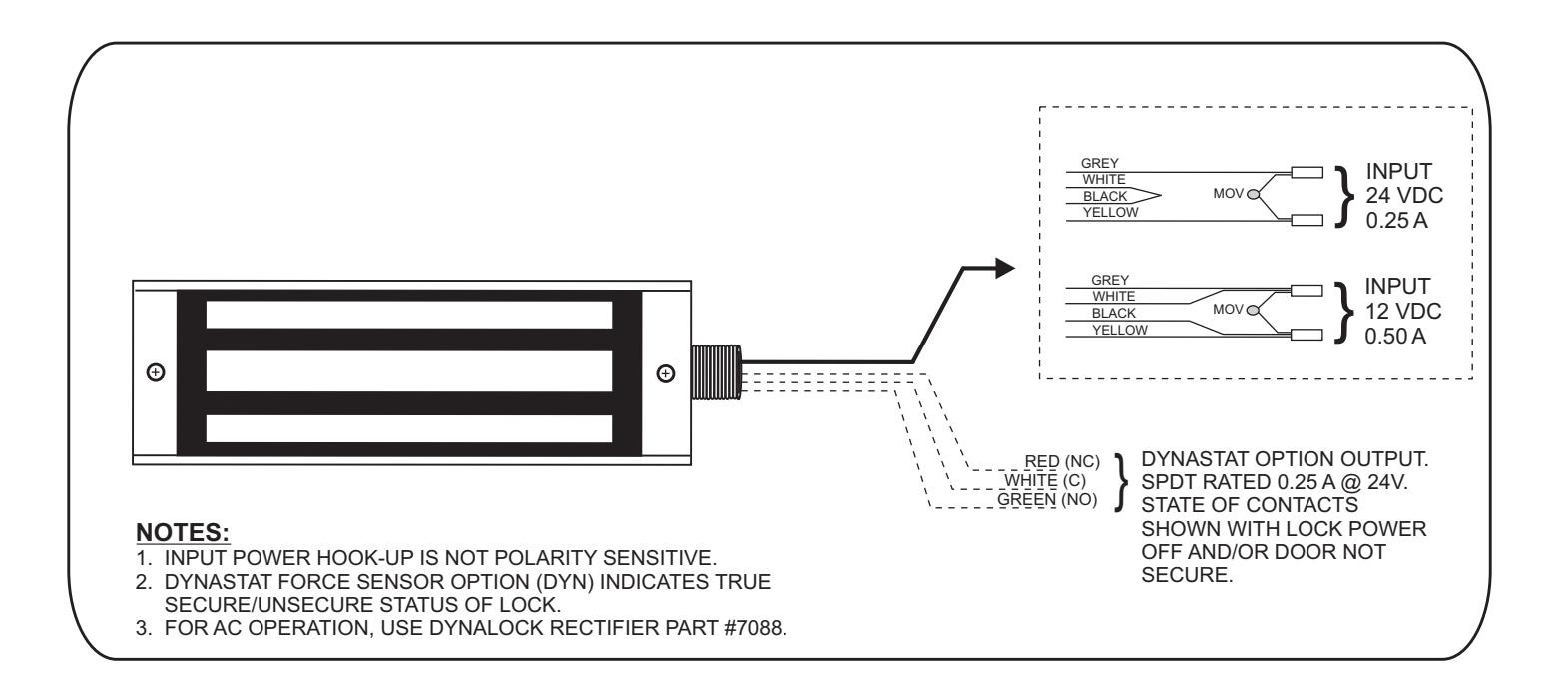
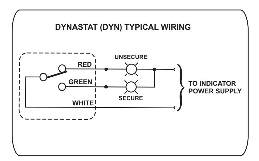
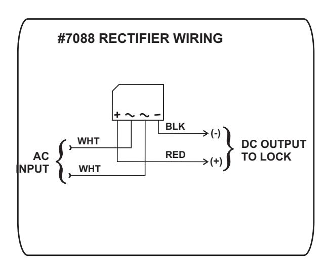
SERIES 2013 ELECTROMAGNETIC GATELOCK WIRING INSTRUCTIONS
WIRING INSTRUCTIONS
2013 BILL OF MATERIAL TOOLS REQUIRED
- 1 Mounting Instructions
- 1 Wiring Instructions
- 1 Electromagnetic Gate Lock
- 1 Hardware Kit consisting of:
- 4 #10 x 1" Phillips Flat Head self-tapping screws
- 4 8-32x3/8" FHS MS U/C
- 4 #8x1" FHS SMS
- 1 0.375" Dx0.235" L Spacer
- 1 1/4" Flat Zinc Washer
- 1 5/16-18x2" FHS Turned
- 1 Spacer Tube
- 1 Un-Cut MOV
- 1 3/16" Hex Key
- **HARDWARE KIT # 301364**
- 1 Electric Drill
- 1 #2 Phillips Head Screw Driver
- 1 Soft-faced Mallet
- 1 3/16" Hex Wrench
- 1 11/32" Drill Bit
- 1 21/32" Drill Bit
- 1 17/64" Drill Bit
- 1 9/64" Drill Bit
- 1 1/4" Drill Bit
- 1 Hammer
- 1 Center Punch
- 1 Pencil
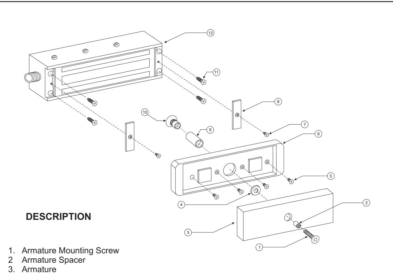
2013 EXPLODED VIEW
5. Armature Housing Screw 6. Armature Housing
- 7. End Cover Screw
4. Steel Washer
- 8. End Cover
- 9. Door Spacer
- 10. Sex Nut
- 11. Mounting Screw
- 12. Magnet Assembly

SERIES 2013 GLB - GATE LOCK BRACKET OPTION INSTALLATION INSTRUCTIONS
MOUNTING PREPARATION
DETERMINE THE PREFFERED MOUNTING CONFIGURATION 1.
From the illustrations below determine whether the Gate Lock Bracket will be used to mount the #2513 armature or magnet assembly. Select the hardware indicated and follow the specific instructions to mount the desired component.
PREPARE THE GATE FOR MOUNTING THE BRACKET 2.
From the three illustrations on the top of page 6 select the one that resembles your gate type and follow the instructions for drilling the mounting screw holes.
** The Gate Lock Bracket is an option that is not included in the standard 2013 lock
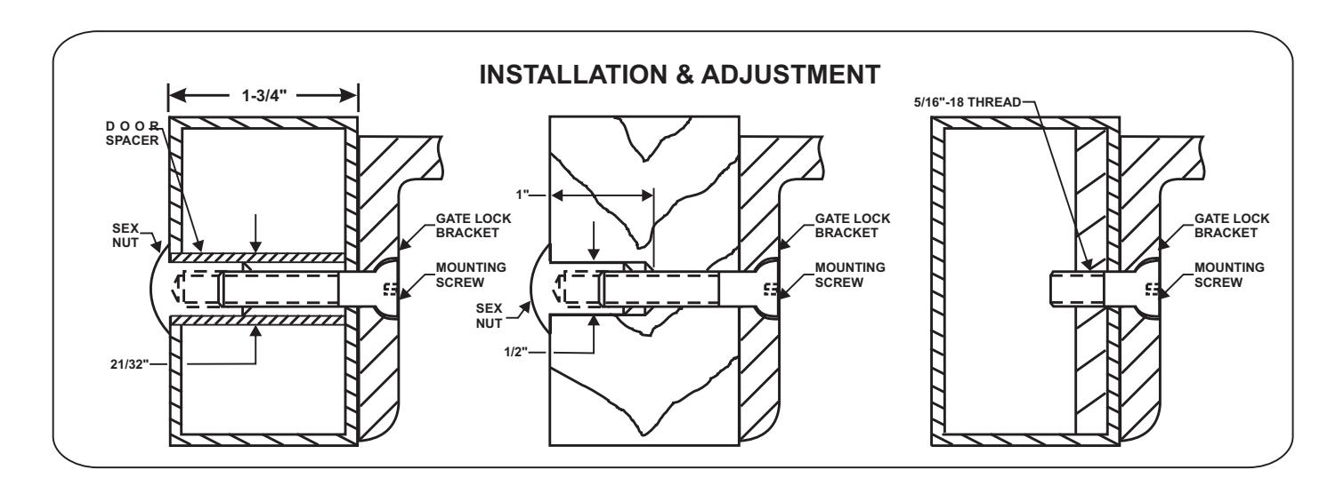
HOLLOW TUBE GATE
Drill an 11/32" diameter hole through gate. From sex nut side only enlarge the 11/32" hole to 21/32" diameter.
SOLID CORE GATE
Drill an 11/32" diameter hole through gate. From sex nut side only drill 1/2" diameter hole to 1" depth.
REINFORCED TUBE GATE
Drill an 17/64" diameter hole and tap for 5/16"-18 thread.
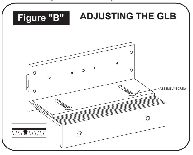
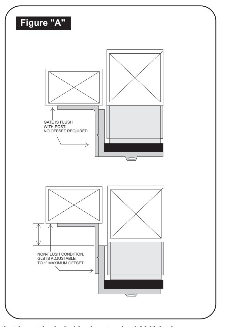
ADJUSTING THE BRACKET 3.
If necessary the Gate Lock Bracket may be adjusted to compensate for unusual clearance and offset conditions on the gate assembly (Refer to Figure "A"). Adjust the bracket as follows:
- Using the 5/32" hex wrench provided loosen the two bracket assembly screws two (2) full turns each. a.
- Slide the two halves of the bracket apart as required. Align the locking rib on the bottom of the upper half with a matching groove on the lower half (Refer to Figure "B") b.
- Firmly re-tighten the assembly screws, verify proper gate and lock alignment and operation and re-adjust as necessary. c.
** The Gate Lock Bracket is an option that is not included in the standard 2013 lock
GATELOCK BRACKET BILL OF MATERIAL TOOLS REQUIRED
- 1 Mounting Instructions
- 1 Gate Lock Bracket Assembly
- 1 Hardware Kit consisting of:
- 4 1/4-20 x 3/4" socket cap head machine screws ( Gate Lock Mtg. Screws )
- 1 5/16-18 x 3/4" hex flat head machine screw ( Armature Mtg. Screw )
- 1 5/32" Hex Wrench
- 2 Mounting Bolt Assemblies, each consisting of:
- 1 5/16-18 x 1-3/4" hex flat head machine screw
- 1 5/16-18 Sex Nut
- 1 1-11/16" long Door Spacer
- 1 Electric Drill
- 1 3/16" Hex Wrench
- 1 11/32" Drill Bit
- 1 21/32" Drill Bit
- 1 1/2" Drill Bit
- 1 17/64" Drill Bit
- 1 Hammer
- 1 Center Punch
- 1 Pencil
** The Gate Lock Bracket is an option that is not included in the standard 2013 lock
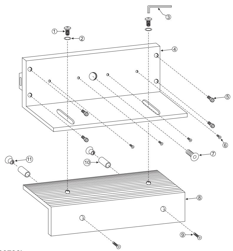
DESCRIPTION
- 1. Assembly Screw
- 2. Lock Washer
- 3. Hex Wrench
- 4. Upper Bracket (300736)
- 5. Lock Mtg. Screw
- 6. Armature Housing Mtg. Screw
- 7. Armature Mounting Screw
- 8. Lower Bracket (300737)
- 9. Mounting Screw
- 10. Door Spacer
- 11. Sex Nut
GATE LOCK BRACKET EXPLODED VIEW

705 Emmett Street Bristol, CT 06011-2728 Phone:(860) 582-4761 Fax:(860) 585-0338
SERIES 2013 GLB2 - GATE LOCK BRACKET OPTION INSTALLATION INSTRUCTIONS
PLEASE READ BEFORE "GLB2" INSTALLATION
Familiarize yourself with the gate and post conditions prior to installation. This kit contains two "L" brackets and hardware to facilitate the installation of a 2013 Gate Lock on a sliding gate: one is predrilled to accept the 2013 Gate Lock and one is predrilled for the armature. Please see the 2013 Gate Lock instructions for more information. Due to the wide diversity of gate designs, additional custom hardware or bracketry may be required to complete the installation.
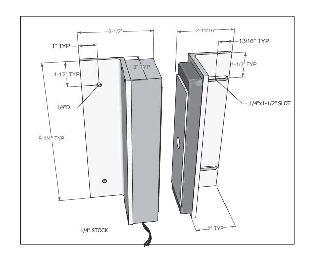
BRACKET MOUNTING
Using the brackets, along with the measurements shown, mark the hole locations on the gate/ post (see next page for how to attach the armature and lock to the brackets).
Drill and tap for 1/4-20 and secure with the (4) 1/4-20x1-1/2" machine screws included
- OR -
Drill 3/16" holes and secure with the (4) #14x1-1/2" included sheet metal screws.
ATTACHING THE ARMATURE AND LOCK TO BRACKETS
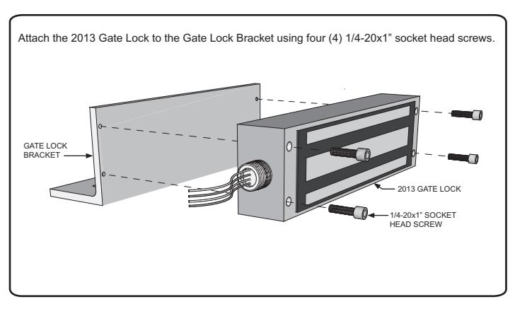
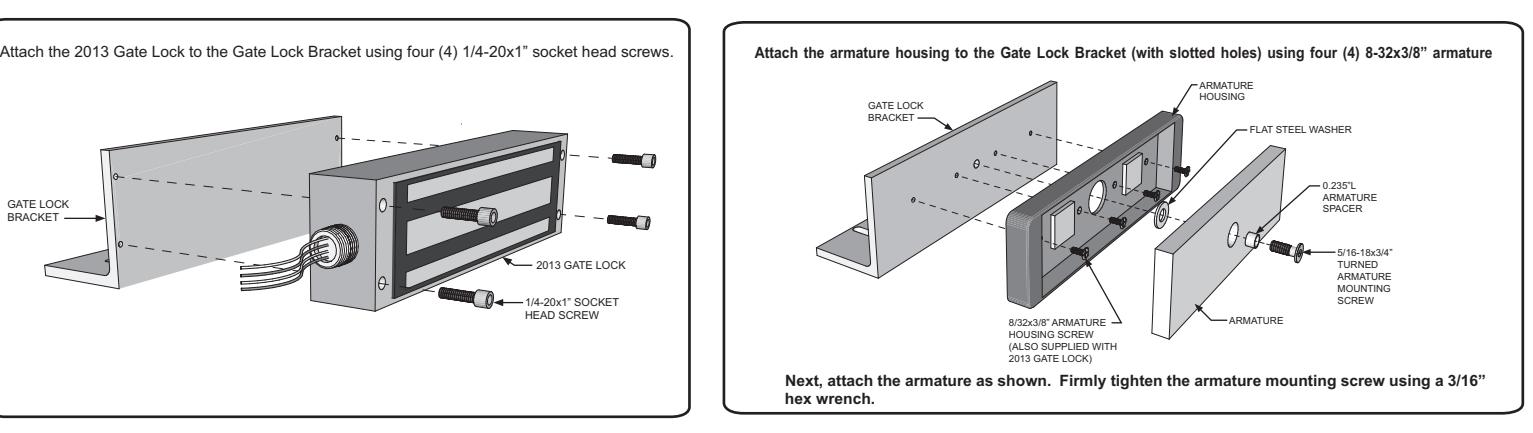
Failure to properly secure the armature to the bracket could result in serious injury or possible security breach.
HARDWARE PACK CONTENTS (PN 301377)
- (1) 5/16-18 x 3/4" FHS MACHINE SCREW (TURNED)
- (1) 0.375"D x 0.235"L ARMATURE SPACER
- (1) 1/4" FLAT WASHER
- (4) 1/4-20 x 1" SOCKET HEAD SCREW
- (4) 1/4-20 x 1-1/2" PHS MACHINE SCREW
- (4) #14 x 1-1/2" PHS SHEET METAL SCREW
- (4) #8-32 x 3/8" FH MACHINE SCREW
01/13
** The GLB2 is an option that is not included in the standard 2013 lock

SERIES 2013 RWE - REAR WIRE ENTRY OPTION SUPPLEMENTAL TEMPLATE
2013 REAR WIRE ENTRY TEMPLATE
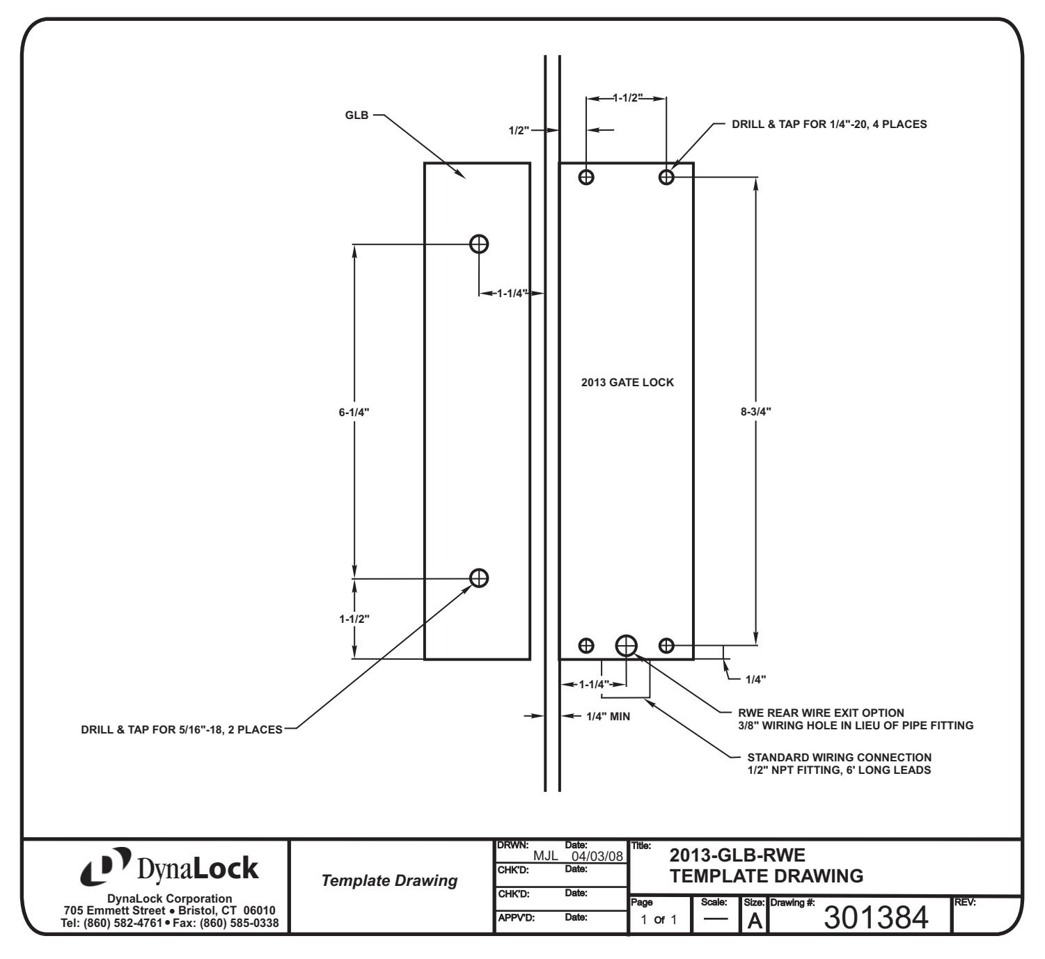
** The REAR WIRE ENTRY is an option that is not included in the standard 2013 lock