DynaLock 2011xTJ20 3000LCxTJ20 Series Installation Instructions
Open the original PDF document
View PDF

INSTALLATION DESCRIPTION
The Series 2011xTJ20 / 3000LCxTJ20 is a 1200 pound holding force top jamb-mounted electromagnetic lock designed to secure a single-inswinging door. The lock requires both installation procedures as described herein and in the separate wiring instructions included.
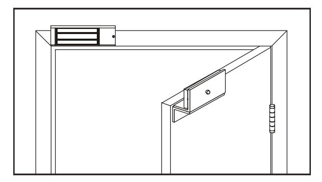
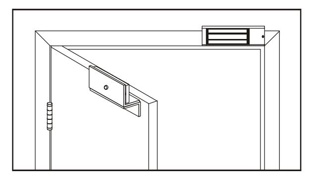
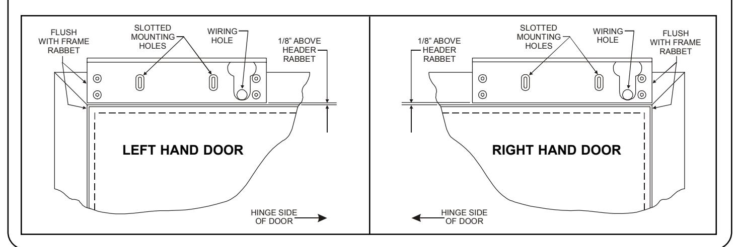
Typical installations of the lock on single-inswing doors:
LEFT HAND DOOR RIGHT HAND DOOR
HANDLING
Care must be taken that the lock face and armature face are kept free of dirt, rust, paint, or any other obstruction which may interfere with the lock and armature making good contact. These faces may be cleaned with a nonabrasive pad and wiped with an oil dampened cloth.
MECHANICAL INSTALLATION
Familiarize yourself with the door and frame conditions. The lock must mount rigidly to the face of the door frame header. The door mounted armature is supplied with an adjustable mounting bracket and hardware that allows it to pivot slightly to compensate for reasonable misalignment.
NOTE: This lock does not change hands to match the hand of the door. Do not remove the coil assembly from the lock housing.
NOTE: If this lock is supplied with the DSM feature be certain to mount the armature with the DSM block extension aligned with the wiring access cover of the lock.
ELECTRICAL INSTALLATION
After mechanical installation is complete the lock needs to be wired to a 12 or 24 VDC/VAC power source. Once low voltage power is supplied the unit is fully operational. All other wiring is for selected options. Refer to the separate wiring instructions included for further information.

Ph/ 860.582.4761 Fx/ 860.585.0338
SERIES 2011xTJ20 / 3000LCxTJ20 ELECTROMAGNETIC LOCK INSTALLATION INSTRUCTIONS
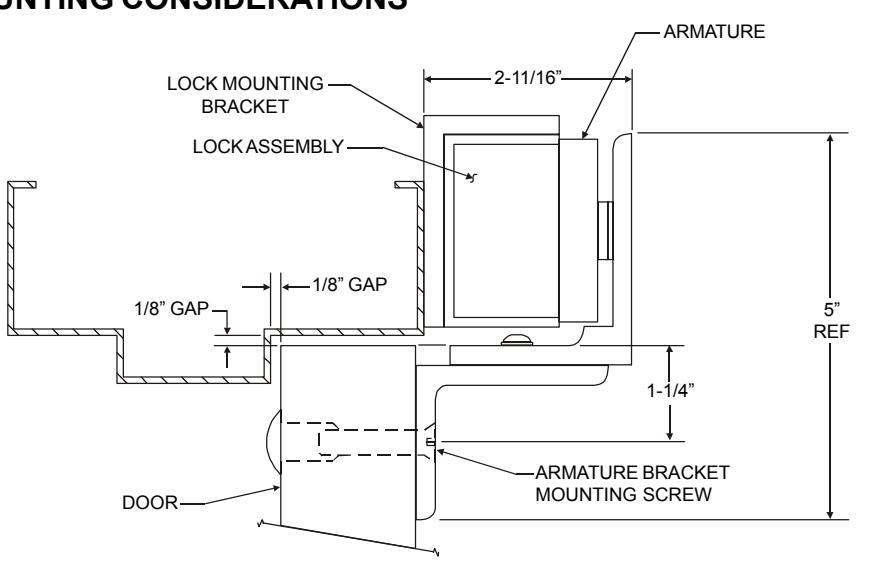
MOUNTING CONSIDERATIONS
- Individual door and frame conditions may vary. Dimensions shown at right are for a typical hollow metal door and frame. 1.
- The lock assembly should be mounted closest to the strike jamb of the frame for maximum performance. Verify that there is proper clearance for the lock assembly at the planned mounting location. 2.
- Electrical wiring for the lock must be routed through the back of the unit, through a hole drilled in the face of the frame header. 3.
INSTALL THE LOCK MOUNTING BRACKET
- Standing at the "pull" side of the door center the lock mounting bracket on the face of the frame header as shown below. Locate and mark the centers of the two slotted mounting holes and the wiring hole. 1.
-
Drill the marked holes in the face of the frame header: 2.
- a. Two (2) 1/8" dia. slotted mounting holes, 1" deep.
- b. One (1) 5/8" dia. wiring hole.
- Attach the lock mounting bracket to the frame header using two (2) #10 x 1" pan head Tek screws. Temporarily tighten the screws. 3.
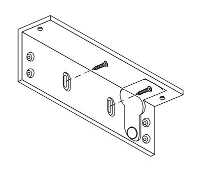

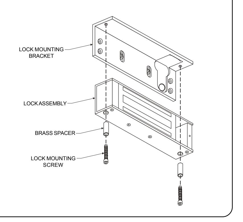
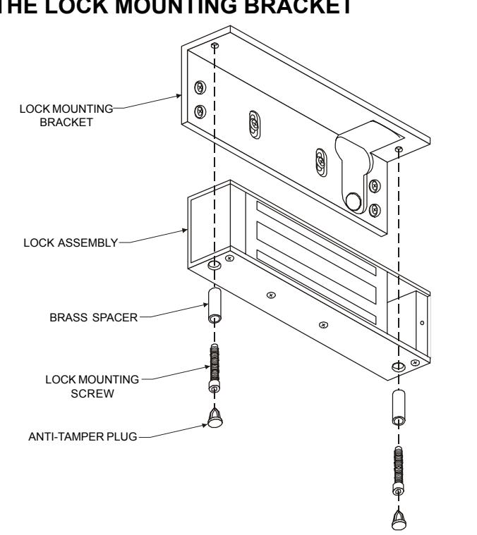
ATTACH THE LOCK ASSEMBLY TO THE LOCK MOUNTING BRACKET
Using the two lock mounting screws and brass spacers attach the lock assembly to the lock mounting bracket as shown. The lock assembly will need to be removed later to add the remaining bracket mounting screws, after all hardware adjustments have been made.
Firmly tighten the mounting screws with a 3/16" hex wrench.
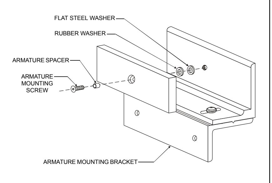
ATTACH THE ARMATURE TO THE ARMATURE MOUNTING BRACKET
Assemble the armature mounting bracket referencing the exploded parts view on page 7.
Locate the armature mounting hardware from the hardware kit and attach the armature to the armature mounting bracket as shown. Firmly tighten the mounting screw with a 3/16" hex wrench.
Failure to properly secure the armature to the bracket could result in serious injury or possible security breach.

INSTALL THE ARMATURE MOUNTING BRACKET
Use the figures below to identify and mark the locations of the armature mounting bracket screw holes on the door. Refer to door and frame prep drawing #301089 for further information. 1.
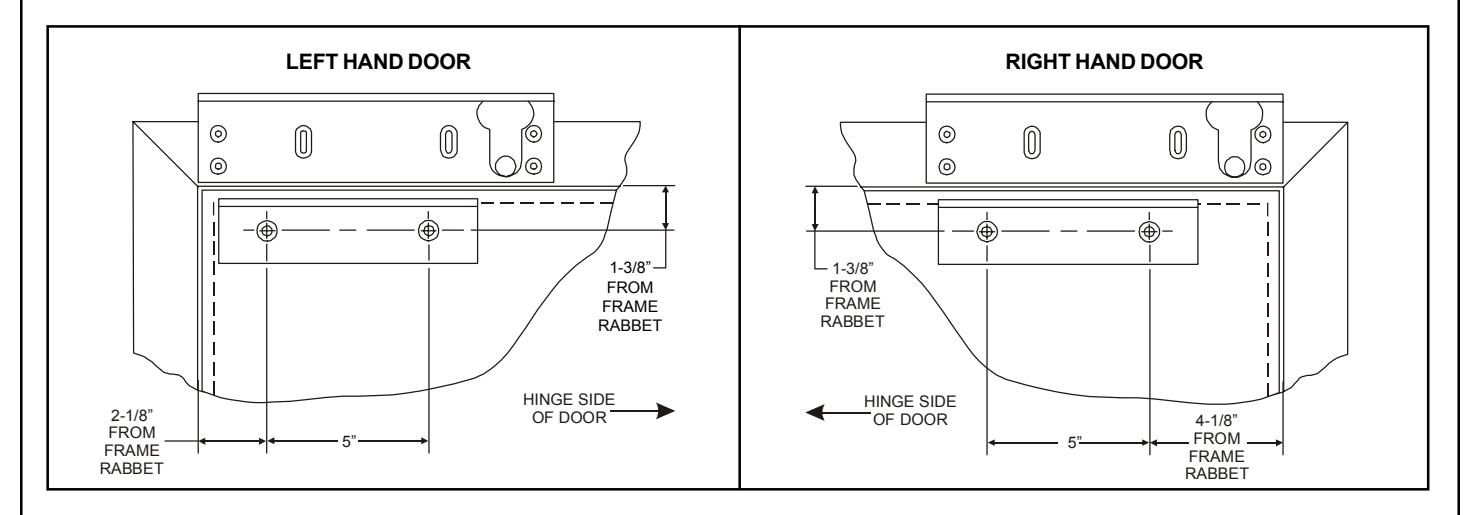
From the illustrations below select the one that resembles your door type and follow the instructions for drilling the two (2) armature mounting bracket screw holes. 2.
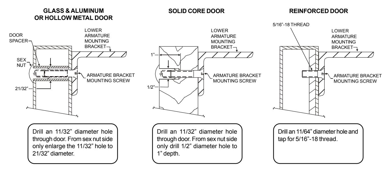
Mount the armature and mounting bracket assembly to the door using the appropriate hardware for you door type. Frimly tighten the mounting screws with a 3/16" hex wrench. 3.
Ph/ 860.582.4761 Fx/ 860.585.0338
SERIES 2011xTJ20 / 3000LCxTJ20 ELECTROMAGNETIC LOCK INSTALLATION INSTRUCTIONS
ARMATURE AND LOCK ADJUSTMENT
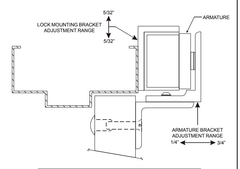
ARMATURE ADJUSTMENT
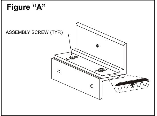
- Using a 5/32" hex wrench temporarily loosen the armature bracket assembly screws roughly 1-1/2 turns to allow the upper armature bracket to move in and out freely (Ref. Figure "A"). 1.
- Close and latch the door. The mating surfaces of the lock and armature should fully contact each other. If necesssary slide the armature in or out to ensure full contact is made with the lock while still allowing the door to properly close and latch. 2.
- When the desired adjustment is acheived slowly open the door, taking care to maintain the position of the armature. Firmly tighten the armature bracket assembly screws with a 5/32" hex wrench, making sure that the locking ribs on the upper and lower bracket halves properly mesh (Ref. Figure "A"). 3.

Verify that the lock face squarely aligns with the armature face. To adjust the lock vertically, remove the lock assembly from the lock mounting bracket, loosen the two adjustment slot screws and reposition the bracket accordingly. 1.
LOCK MOUNTING BRACKET FINAL ASSEMBLY
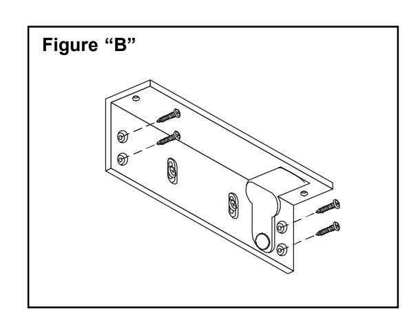
- Following adjustment (if required) firmly re-tighten the adjustment slot screws on the lock mounting bracket. Using the bracket as a physical template mark the centers of the four fixed mounting screw holes. Drill the holes in the header using a 1/8" drill, 1" deep. 1.
- Complete the installation of the lock mounting bracket using four (4) #10 x 1 pan head Tek screws (Ref. Figure "B"). Firmly tighten all screws with a #2 phillips head screwdriver. 2.

SECURE THE LOCK ASSEMBLY TO THE LOCK MOUNTING BRACKET
- Secure the lock assembly to the mounting bracket using the two lock mounting screws and brass spacers. Firmly tighten the the mounting screws with a 3/16" hex wrench. 1.
- Install the anti-tamper plugs from the hardware kit over the lock mounting crews. Gently tap into place using a rubber mallet. 2.
- The mechanical installation is now complete. Refer to the separate 2000/3000/300LC Wiring Instructions to complete the electrical installation. 3.
EXPLODED PARTS VIEW LEGEND
| ITEM | DESCRIPTION | PART NO. | ITEM | DESCRIPTION | PART NO. |
|---|---|---|---|---|---|
| 1 | Lock Assembly | Consult Factory | 10 | Armature Bracket Assy. Screw | |
| 2 | Lock Mounting Bracket | 301073 | 11 | Lock Washer | |
| 3 | Armature | 300013 | 12 | Anti-Tamper Plug | |
| 4 | Upper Armature Bracket | 300724 | 13 | Lock Bracket Mounting Screw | |
| 5 | Lower Armature Bracket | 300725 | 14 | Armature Mounting Screw | |
| 6 | Access Cover / Board Assy. | 300906 | 15 | Armature Spacer |
Hardware Kit
P/N 301074 |
| 7 | Access Cover Screw | 300608 | 16 | Rubber Washer | |
| 8 | Brass Spacer | 300468 | 17 | Flat Steel Washer | |
| 9 | Lock Mounting Screw | 300603 | 18 | Sex Nut |
Note: Refer to Page 7 for parts locations.
| 10 | Armature Bracket Assy. Screw | ||
| 11 | Lock Washer | ||
| 12 | Anti-Tamper Plug |
Hardware Kit
P/N 301074 |
|
| 13 | Lock Bracket Mounting Screw | ||
| 14 | Armature Mounting Screw | ||
| 15 | Armature Spacer | ||
| 16 | Rubber Washer | ||
| 17 | Flat Steel Washer | ||
| 18 | Sex Nut | ||
| 19 | Door Spacer | ||
| 20 | Armature Bracket Mtg. Screw | ||
EXPLODED PARTS VIEW
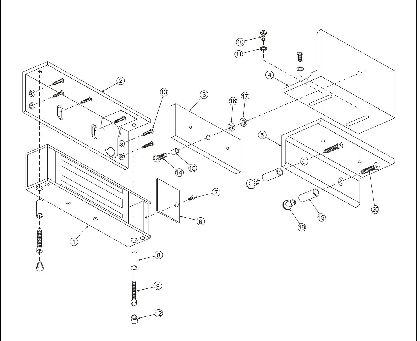
Note: Refer to Page 6 for parts legend.