DynaLock 2000 3000LC Series -Installation Instructions
Open the original PDF document
View PDF

SERIES 2011 AND 3000LC ELECTROMAGNETIC LOCK MOUNTING INSTRUCTIONS FOR A SINGLE OUTSWING DOOR

PLEASE READ BEFORE ATTEMPTING INSTALLATIONS
Attention to detail and familiarizing yourself with the actual door entrance conditions and installation instructions will prove invaluable as you begin installation of this high quality lock.
* NOTE: If this lock is supplied with the DSM feature be certain to mount the armature with the DSM block extension adjacent to the wiring access cover.
HANDLING
The Electromagnetic lock and armature are ruggedly constructed and designed to provide years of trouble free service. Care must be taken during installation and during actual use so that the lock face and the armature face are free of dirt, rust, burrs, paint, or any other obstruction which may interfere with the lock and armature making good contact. TENANCE
MAINTENANCE
The lock coil assembly and door armature have been plated for maximum corrosion resistance but to insure peak lock performance, clean the lock and armature faces with a mild detergent and a clean soft cloth, then apply a light coat of WD40 to lubricate and protect these surfaces. This need only be done when dirt build-up is noticed.
MOUNTING
The lock coil must mount rigidly to the underside of the door frame header and against the vertical lock jamb located opposite the jamb that contains the hinges. The door mounted armature is supplied with hardware that allows it to pivot slightly about the central mounting screw to compensate for door mis-alignment. Armature mounting hardware is supplied for a standard 1-3/4" thick door.
For wider doors order the following special armature screw packs:
Part # 300687 for 2" doors.
Part # 300688 for 2-1/4" doors.
DynaLock Corp. 705 Emmett Street P.O. Box 2728 Bristol, CT 06011-2728 Phone (860)582-4761 Fax (860)585-0338
INSTALLATION
1. Inspect the door frame and determine if an angle bracket, filler or spacer plate is required. The lock will require a 2" wide stop.
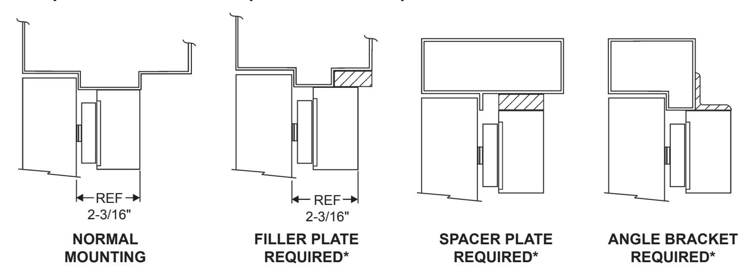
* See Price Book or Call DynaLock Corp.
-
2.
Determine the hand of door LHRB or RHRB and look at the template edge for proper positioning of template.
- A. Fold the template on the dotted line to form a 90 Degree angle.
- B. With the door in the closed and latched position, place the template against the header and door.
- C. Transfer all hole locations to both door and header with center punch.
- D. Remove the template from the door.
3. Prepare the door for ARMATURE MOUNTING
From the three illustrations below select one that resembles your door type, and follow the instructions for the armature screw mounting hole. On either side of this location drill a 1/4" dia. hole 9/16" deep. (see Template).
GLASS AND ALUMINUM OR HOLLOW METAL DOOR SOLID CORE DOOR REINFORCED DOOR
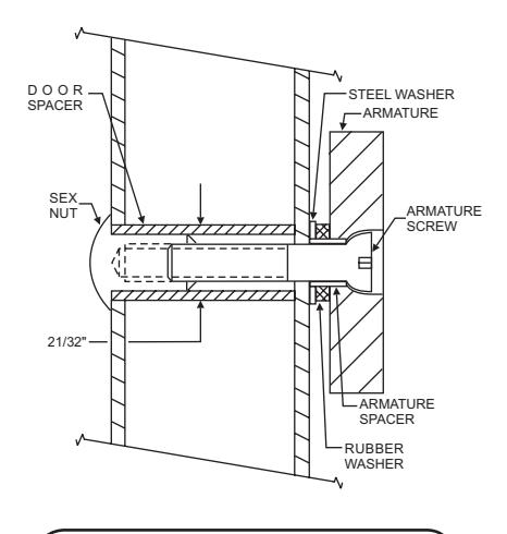
Drill an 11/32" diameter hole through the door. From the sex nut side only enlarge the hole to 21/32" diameter.
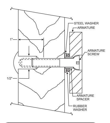
Drill an 11/32" diameter hole through the door. From the sex nut side drill 1/2" diameter hole to 1" depth.
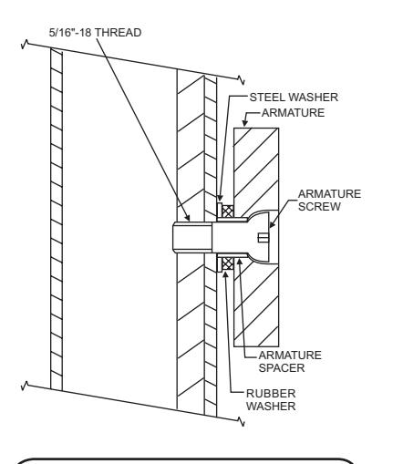
Drill a 17/64" diameter hole and tap for 5/16-18 thread
4. MOUNTING the ARMATURE to the door
Refer to illustrations in step 3 to verify the correct assembly of mounting hardware and mount the armature to the door. The center screw should be finger tight plus 1/8" to 1/4" turn with Hex wrench. Failure to properly secure an armature to the door could result in serious injury or security breach.
5. PREPARE the HEADER for baseplate mounting
Refer to Template and drill two 1/8"dia. mounting and 9/16" wiring hole where shown.
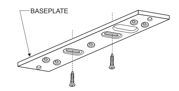
6. MOUNTING the BASEPLATE to the header
Separate the baseplate from the lock housing with the Hex wrench. Place the baseplate against the header with the counter sunk slots visible, and the large slot over the wire hole. Using an electric drill with a Phillips bit attach the baseplate to the header at both slotted locations with screws provided. Tighten the screws just snug enough to allow for final adjustment.
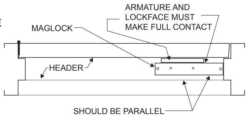
7. ALIGNING the LOCK and ARMATURE
Close and latch the door. Temporarily mount the lock to the baseplate and verify the lock face and armature are making full contact for the entire armature length. If any adjustment is required gently tap the baseplate with a soft mallet until full contact is achieved. Mark two baseplate corner locations lightly with a pencil for reference. Remove lock from baseplate and tighten both adjustment screws. Drive the remaining 5 screws into the header using the baseplate as a physical template. Screw heads must not project above the baseplate.
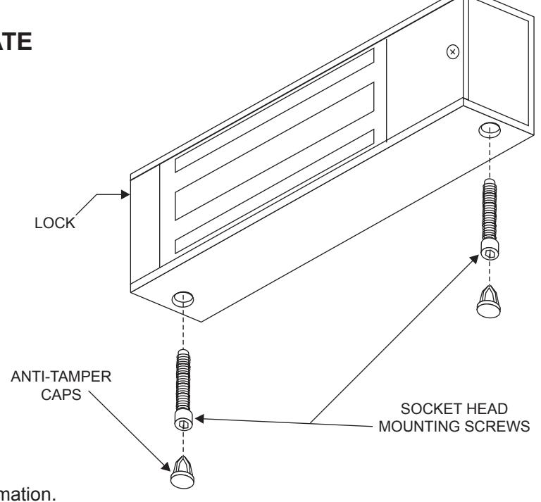
8. ATTACHING the LOCK to the BASEPLATE
With the Hex wrench permanently fasten the lock to the baseplate with the two 1/4"-20 x 1-1/4" machine screws removed in Step 6. Install the tamper plugs over the mounting screws with the soft mallet.
9. THE MECHANICAL INSTALLATION
The mechanical installation is now complete. Refer to the wiring instructions manual for additional information.
- (1) Electric Drill
- (1) #2 Phillips Screw Driver
- (1) Soft Faced Mallet
- (1) Hammer
- (1) Center Punch
- (1) 3/16" Hex Wrench
- (1) Pencil & Tape
Drill Bits: 1/8", 1/4", 17/64", 11/32", 1/2",9/16", 21/32"
REQUIRED TOOLS BILL OF MATERIALS
- (1) LOCK ASSEMBLY
- (1) ARMATURE
- (1) HARDWARE KIT
- (1) MOUNTING TEMPLATE
- (1) INSTALLATION MANUAL
- (1) WIRING MANUAL
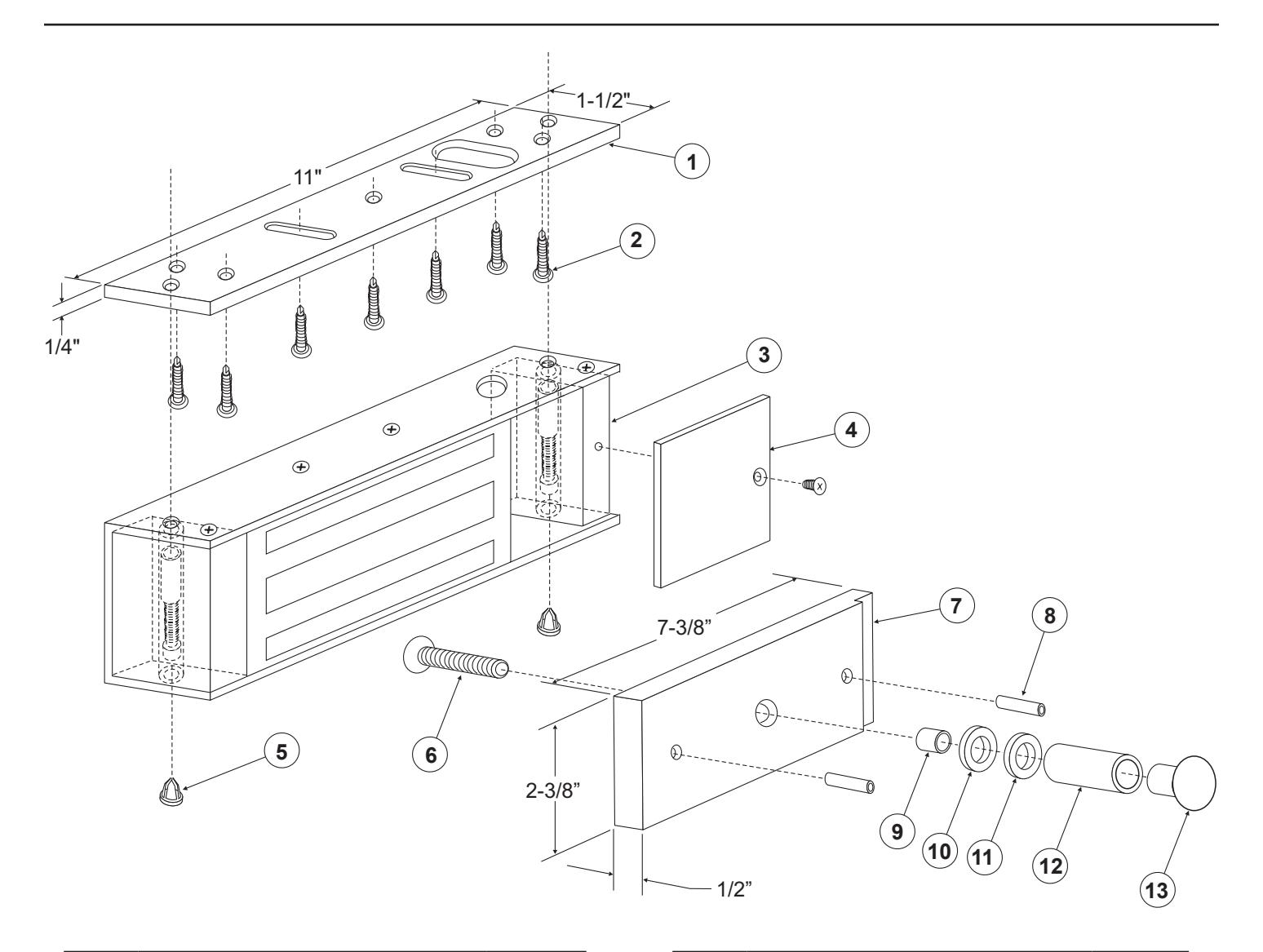
| ITEM | DESCRIPTION | PART # |
|---|---|---|
| 1 | Baseplate | 300110 |
| 2 | #10x1" Self-Tapping Screw (7) | * |
| 3 | Housing Assembly | 300107 |
| 4 | Access Cover | 300009 |
| 5 | Anit-Tamper Plug (2) | * |
| 6 | 5/16-18x2" Armature Screw | * |
| 7 | Armature | 300013 |
| ITEM | DESCRIPTION | PART # |
|---|---|---|
| 8 | Anti-Spin Pin (2) | * |
| 9 | Armature Spacer | * |
| 10 | Rubber Washer | * |
| 11 | 1/4" Steel Washer | * |
| 12 | Spacer Tube | * |
| 13 | Sex Nut | * |
* Hardware Kit P/N 300760