DynaLock 1600 Series Brochure
Open the original PDF document
View PDF

1600 Series Electric Strikes
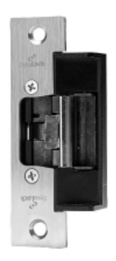

Description
DynaLock 1600 Series Electric Strikes are universally adaptable to suit all door and frame types and accomodate most locking devices with up to a 3/4" latch projection. To simplify ordering and speed installation all 1600 Series models feature 12/24V AC/DC field-selectable operation, dial-selectable fail-safe or fail-secure operating mode, 1/4" horizontal adjustment and modular, plug-in wire connections.
All models are also available in a low-profile, 1-1/16" backset version, for narrow-style alumunium frames, which accept up to a 5/8" latch projection. Optional latch/keeper monitor switches are also available.
Typical applications include non-fire rated doors in most commercial, industrial and institutional centers, retail outlets and health care facilities.
Features
- Field Selectable Lock Mode
- Field Selectable Voltage
- Horizontal Adjustability
- •Low Profile Version
- Plug-in Wire Connections
- UL Listed 1034 Burglary Resistant
- •Tested To 70 ft. lbs. Dynamic Force
- •Tested To Over 1,000,000 Cycles
- •3 Year Limited Warranty
Options
LMS Lock Monitor Switches. Latch/Keeper status monitor switches (see page 3 for details).
SF Special Finish. US32D standard. US3, US4, US10, US10B and US32 available.

1600 Series Electric Strike Selection
Part Number Configuration
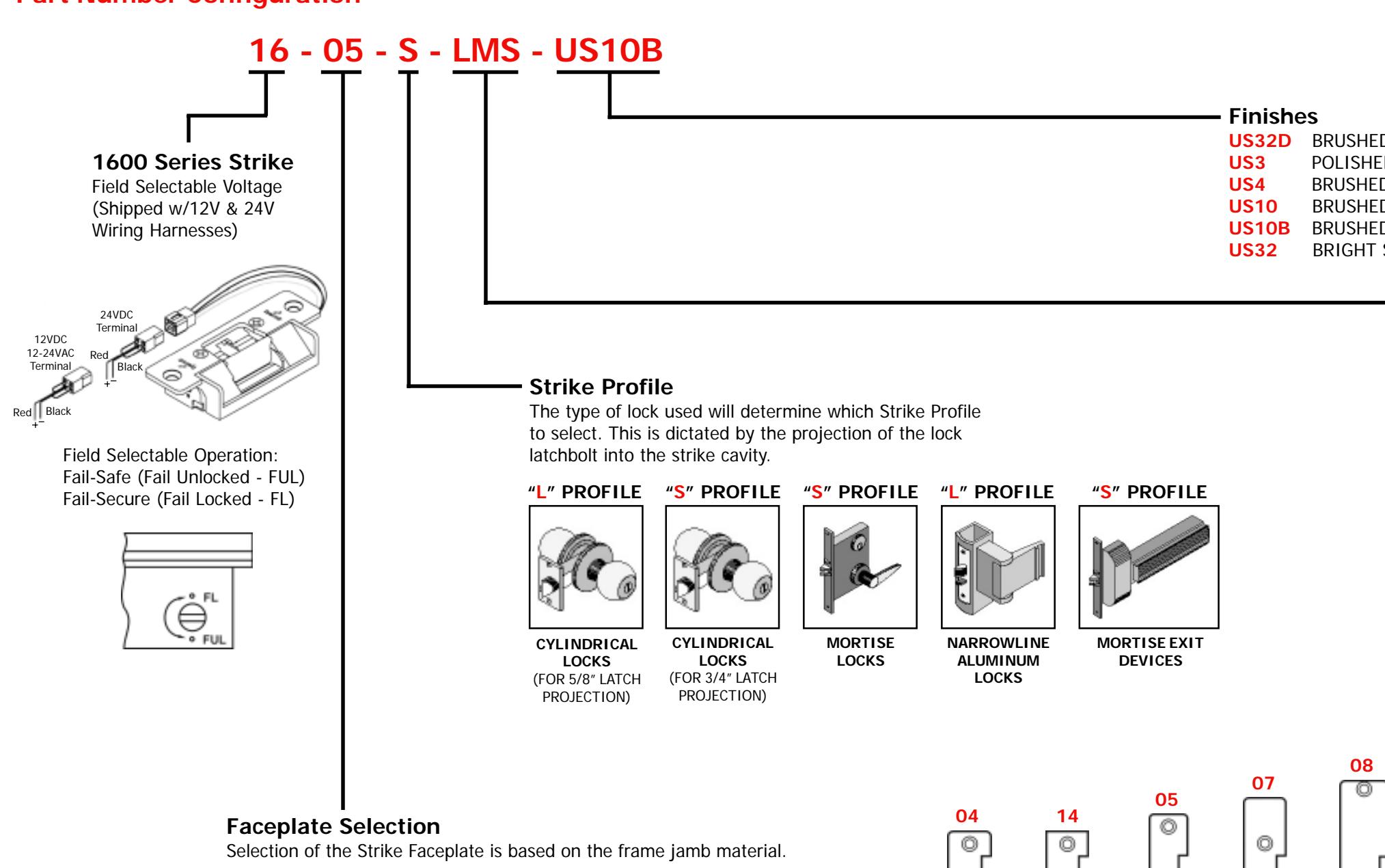
US32D BRUSHED STAINLESS STEEL (STANDARD)
POLISHED BRASS BRUSHED BRASS
BRUSHED LIGHT BRONZE US10B BRUSHED DARK BRONZE BRIGHT STAINLESS STEEL
LMS Lock Monitor Switches (Optional)
Two SPDT switches monitor latchbolt projection and locked/unlocked condition of strike keeper.
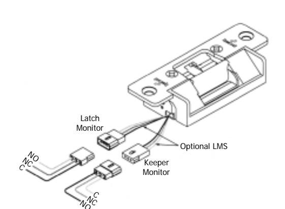
Latch Monitor Wires
Black = Common (C)
Blue = Normally Closed (NC)
Orange = Normally Open (NO)
Keeper Monitor Wires
Black = Common (C)
Yellow = Normally Closed (NC)
Green = Normally Open (NO)
Note: Contacts are indicated with the keeper in a closed and locked position,
with no latch present.
- 04 1-1/4" x 4-7/8" ANSI ROUND CORNER (ALUMINUM OR WOOD FRAMES)
- 1-1/4" x 4-7/8" ANSI SQUARE CORNER (HOLLOW METAL OR WOOD FRAMES)
- 1-1/8" x 5-7/8" ROUND CORNER (ALUMINUM OR WOOD FRAMES) 05
- 1-1/4" X 6-7/8" ROUND CORNER (ALUMINUM OR WOOD FRAMES)
2
1-7/16" X 7-15/16" ROUND CORNER (ALUMINUM OR WOOD FRAMES)
| 04 | 14 | 05 | 07 | |
|---|---|---|---|---|
| © | © | © | © | |
|
?
]
⊚] |
0 | © | | 0 |
| GENERAL ELECTRICAL SPECIFICATIONS | |||||||
|---|---|---|---|---|---|---|---|
| VOLTAGE | DUTY | SOUND | AMPS* | OHMS** | |||
| 12VDC | Continuous | Silent | 0.375 | 37 | |||
| 24VDC | Continuous | Silent | 0.190 | 148 | |||
| 12 to 24VAC | Intermittent | Buzz | 0.565/0.280 | 148 | |||
* Ratings are based on max. current draw @ +10°C and include initial
3
** Nominal resistance at +25°C +- 7%.
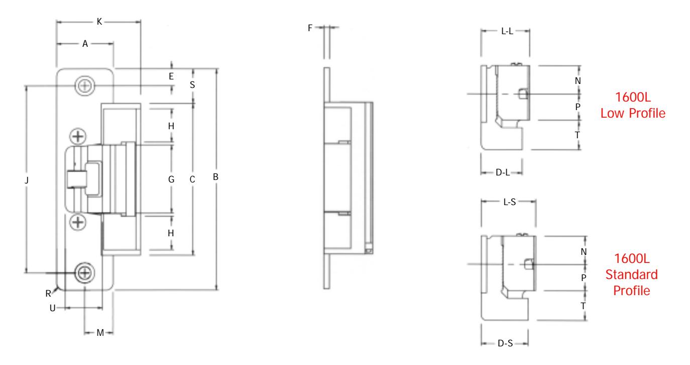
1600 Series Electric Strikes
Profile Dimensions
|
D
IM EN SI O N |
A | B | C |
D
-S |
D
-L |
E | F | G | H |
|---|---|---|---|---|---|---|---|---|---|
|
FR
AC TI O NA L IN CH ES |
1/
1- 4 |
7/
4- 8 |
/3
3- 11 2 |
5/
1- 32 |
1/
1- 16 |
3/
8 |
1/
8 |
1/
1- 2 |
/6
47 4 |
|
DE
CI M AL I NC HE S |
1.
25 0 |
4.
87 5 |
3.
34 4 |
1.
15 6 |
1.
06 3 |
.3
75 |
.1
25 |
1.
50 0 |
.7
34 |
|
M
ET RI C M IL LI M ET ER S |
31
.7 5 |
12
3. 83 |
84
.9 9 |
29
.0 0 |
27
.0 0 |
9.
53 |
3.
18 |
38
.1 0 |
18
.5 9 |
|
D
IM EN SI O N |
J | K |
S
L- |
L-
L |
M | N | P | R | S |
|---|---|---|---|---|---|---|---|---|---|
|
FR
AC TI O NA L IN CH ES |
1/
8 4- |
27
/3 2 1- |
13
/6 1- 4 |
1/
1- 16 |
5/
8 |
5/
8 |
/6
37 4 |
5/
32 |
/6
49 4 |
|
CI
NC S DE M AL I HE |
4.
12 5 |
1.
84 4 |
1.
20 3 |
1.
06 3 |
.6
25 |
.6
25 |
.5
78 |
.1
56 |
.7
66 |
|
M
ET RI C M IL LI M ET ER S |
10
4. 78 |
46
.9 9 |
30
.5 6 |
26
.9 6 |
.8
8 15 |
.8
8 15 |
3
14 .6 |
06
4. |
19
.4 5 |
Note: Dimensions shown above are with 04 faceplate.
|
SI
O T D IM EN N |
D
ef lt au |
in
M |
M
ax |
|---|---|---|---|
|
FR
AC TI O NA L IN CH ES |
/3
21 2 |
1/
2 |
/6
49 4 |
|
DE
CI M AL I NC HE S |
0.
65 6 |
0.
50 0 |
0.
76 6 |
|
C
S M ET RI M IL LI M ET ER |
16
.5 1 |
12
.4 9 |
19
.5 1 |
|
SI
O U D IM EN N |
D
ef lt au |
in
M |
M
ax |
|---|---|---|---|
|
FR
AC TI O NA L IN CH ES |
/1
13 6 |
45
/6 4 |
/3
31 2 |
|
DE
CI M AL I NC HE S |
0.
81 3 |
0.
70 3 |
0.
96 9 |
|
C
S M ET RI M IL LI M ET ER |
.8
20 0 |
17
.8 1 |
24
.7 9 |
Note: T and U dimensions are relative to horizontal adjustability.
DYNALOCK CORPORATION
705 EMMETT STREET / PO BOX 2728 BRISTOL, CT 06011-2728
PHONE: 877-DYNALOCK / FAX: 860-585-0338 E-MAIL: INFO@DYNALOCK.COM WEBSITE: WWW.DYNALOCK.COM