Dorma 9000 Series Electric Exit Decvice Kit Installation Instructions
Open the original PDF document
View PDF

ELECTRIC EXIT DEVICE KIT INSTALLATION INSTRUCTIONS MOTOR DRIVE ELECTRIC LATCH RETRACTION
1550K-MDD
DORMA 9000 SERIES
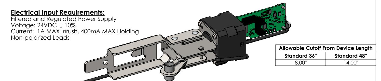
PROVIDES SIMULTANEOUS ELECTRIC LATCH RETRACTION AND DOGGING (TOUCH BAR DEPRESSED)
Installation:
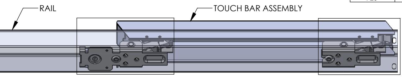
- 1. Separate the rail from the touch bar assembly.
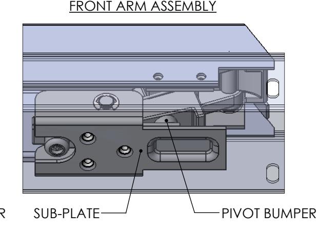
- 2. Separate the sub-plate from the front arm assembly.
- 3. Remove and discard the pivot bumper from the front pivot arm.
- 4. Attach the sub-plate to the front arm assembly.
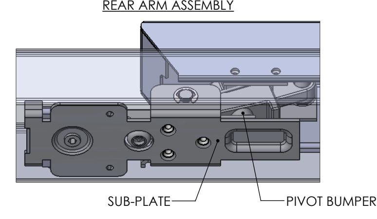
- 5. Separate the rear arm assembly from the touch bar assembly.
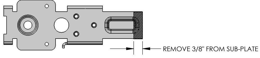
- 6. Separate the sub-plate from the rear arm assembly and modify.
- 7. Remove and discard the pivot bumper from the rear pivot arm.
| 2-Conductor Wire Run | |||
|---|---|---|---|
| Distance | Wire Gauge | ||
| 70' | 22 | ||
| 110' | 20 | ||
| 180' | 18 | ||
| 280' | 16 | ||
| 450' | 14 | ||
| 720' | 12 | ||
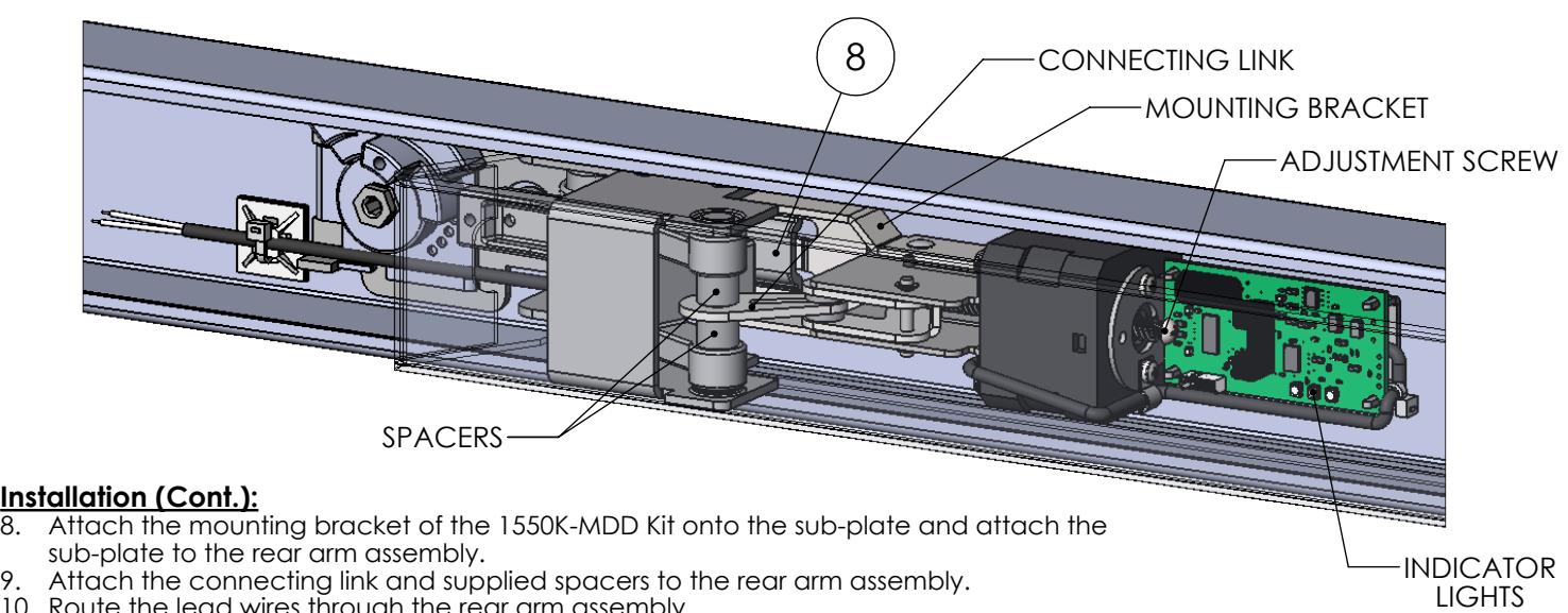
- 10. Route the lead wires through the rear arm assembly.
- 11. Attach the rear arm assembly to the touch bar assembly.
- 12. Attach the rail to the touch bar assembly.
- 13. Secure the lead wires to the inside of the rail using the supplied ty-wrap mount and ty-wrap.
- 8 14. Apply the supplied technical assistance labels to the chassis cover and the end cap. Do not remove any regulatory labels adhered to the device.
Motor Drive Electric Latch Retraction Adjustment:
- 1. Verify the device is properly adjusted for mechanical operation. Electric operation should not exceed the mechanical operation or there will be a high risk of damage to the device. We suggest setting the latch retraction under electric operation at 1/16" less than the latch retraction under mechanical operation.
- 2. Locate the adjustment screw in the rear of the motor assembly. Rotate the adjustment screw clockwise to increase the latch retraction or counterclockwise to decrease the latch retraction.
Onboard Indicator Light Assignments:
Maintain input power to the exit device and check the onboard indicator lights.
Remove input power before attempting a solution.
|
Green
(Power) |
Yellow
(Sensor) |
Red
(Error) |
Indication | Possible Solution |
|---|---|---|---|---|
| Off | Off | Off | No Power. |
Connect the wiring between the power
supply and the exit device. |
| On | On | Off |
Normal Operation. The touch bar is retracted to the dogged
position and dogged; the latch is retracted by default. The device is allowed 2 attempts. |
|
| On | Off | On |
Error in operation. The touch bar did not retract to the dogged
position within 2 attempts. |
Rotate the adjustment screw
counterclockwise to decrease the latch retraction. |
| On | On | On |
Error in operation. Without power being removed, the touch
bar went from being dogged to unintentionally being extended, and then the touch bar did not retract to the dogged position within 2 attempts. |
Clear the jam condition manually. |
| On | Blink | On |
Error in operation. The touch bar did not extend from the
dogged position when the power was last removed. The device will not attempt a retraction. |
Clear the jam condition manually. |
| On | Blink | Simultaneous |
Error in operation. The input voltage dropped below the
specification during operation. |
Decrease the wire run or increase the wire
gauge. |
| On | Alternating Blink | Error in operation. An electronics fault was detected. | An electronics replacement is required. |