Door Position Switch Installation Instructions – I-EA00289
Open the original PDF document
View PDF

DEVICES COVERED IN THIS DOCUMENT: 2-659-0369
1. DESCRIPTION
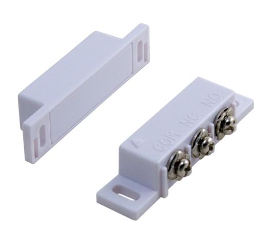
2. SPECIFICATIONS
| Voltage maximum: | 30 VAC/VDC |
|---|---|
| Current maximum: | 0.24 A |
| Power maximum: | 3.0 W |
| Electrical configuration: | SPDT |
| Wiring (12" 22AWG): | open or closed |
| Gap distance maximum: | 2" |
Specifications are subject to change without prior notice. All values measured in specific
conditions.
3. PRECAUTIONS

- Shut off all power going to header before attempting any wiring procedures.
- Maintain a clean and safe environment when working in public areas.
- Constantly be aware of pedestrian traffic around the area.
- Always stop pedestrian traffic through the doorway when performing tests that may result in unexpected reactions by the door.
- Always check placement of all wiring before powering up to ensure that moving door parts will not catch any wires and cause damage to equipment.
- Ensure compliance with all applicable safety standards (i.e. ANSI A156.10/19) upon completion of installation.
-
DO NOT attempt any internal repair of the components. All repairs and/or component replacements must be performed by Hager. Unauthorized disassembly or repair:
- 1.May jeopardize personal safety and may expose one to the risk of electrical shock.
- 2.May adversely affect the safe and reliable performance of the product resulting in a voided warranty.
Rev XX Page 1 of 2
Rev Date: XX/XX/XXXX

4. INSTALLATION
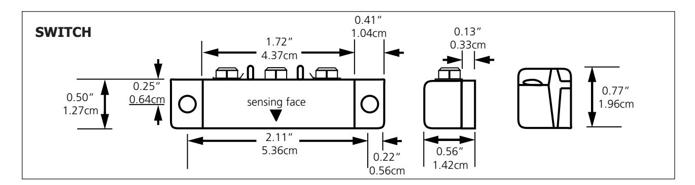
- 1. Determine mounting location on door frame.
- 2. Mark and drill two holes for mounting the switch.
- 3. Mount the switch to the frame with the screws.
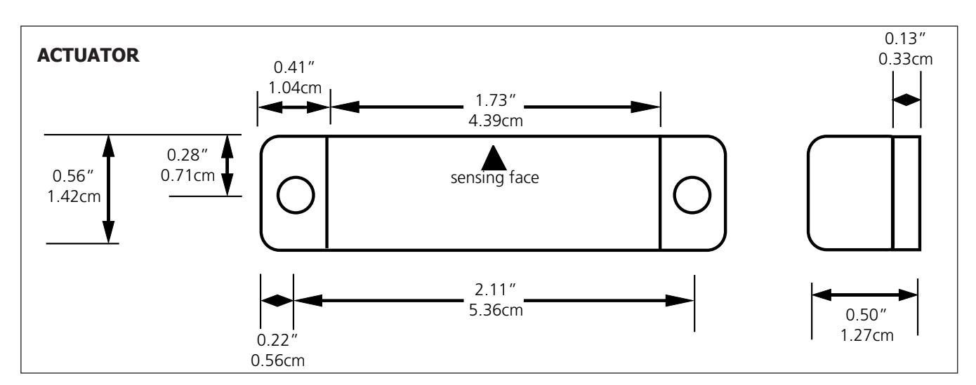
- 4. Align the magnet on the door with the switch.
- 5. Mark and drill two holes for mounting the magnet.
- 6. Mount the magnet with the screws.
- 7. Wire the switch as needed for the application.
INSTALLATION/SERVICE COMPLIANCE EXPECTATIONS
The sensor manufacturer cannot be held responsible for incorrect installations or inappropriate adjustments of the sensor/device; therefore, the sensor manufacturer does not guarantee any use of the sensor outside of its intended purpose.
The sensor manufacturer strongly recommends that installation and service technicians be AAADM-certifi ed for pedestrian doors, IDA-certifi ed for doors/gates, and factory-trained for the type of door/gate system.
Installers and service personnel are responsible for executing a risk assessment following each installation/service performed, ensuring that the sensor system installation is compliant with local, national, and international regulations, codes, and standards.
Once installation or service work is complete, a safety inspection of the door/gate shall be performed per the door/gate manufacturer recommendations and/or per AAADM/ANSI/DASMA guidelines (where applicable) for best industry practices. Safety inspections must be performed during each service call – examples of these safety inspections can be found on an AAADM safety information label (e.g. ANSI/DASMA 102, ANSI/DASMA 107).
Verify that all appropriate industry signage and warning labels are in place.


Rev XX Rev Date: XX/XX/XXXX Page 2 of 2