Dexter ED2000 Rim Panic Fire Installation Instructions 111061
Open the original PDF document
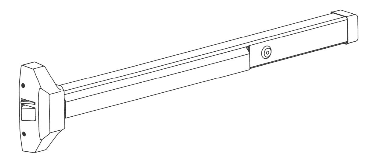
View PDFREVERSIBLE PANIC / FIRE EXIT RIM DEVICES
INSTALLATION INSTRUCTIONS
These instructions are presented in step by step sequence. Attach a template to tape to your door and frame as an aid to prepare for device mounting.
Please read thoroughly before installation.
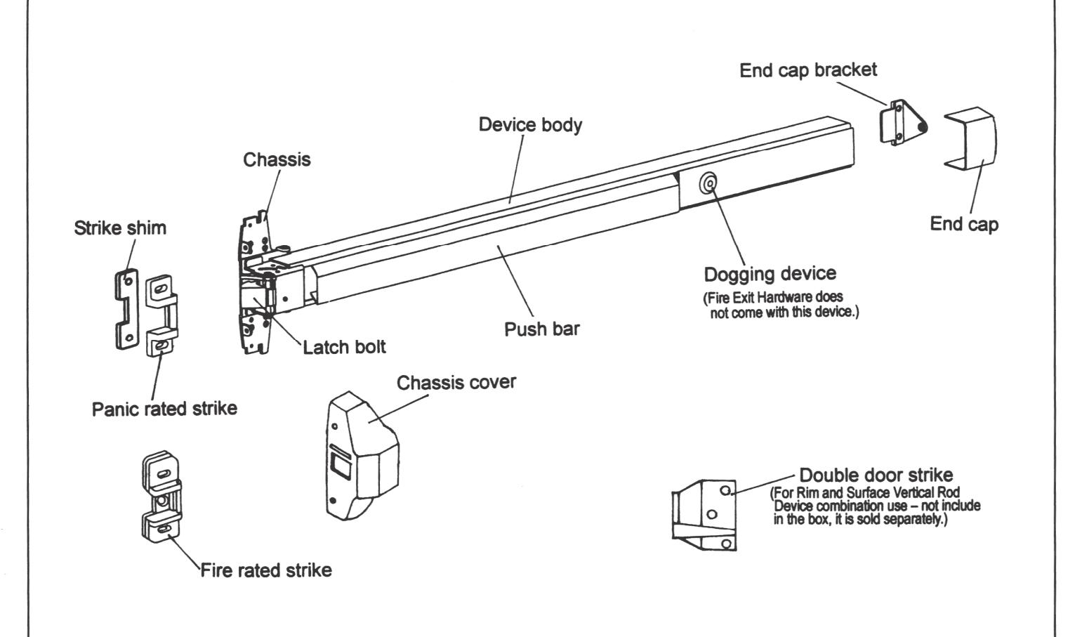
NAME OF MAIN PARTS
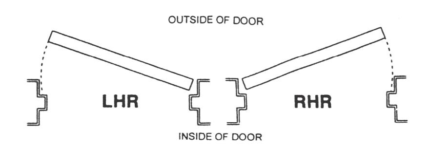
DOOR HANDING
Use this diagram to determine the hand of door.
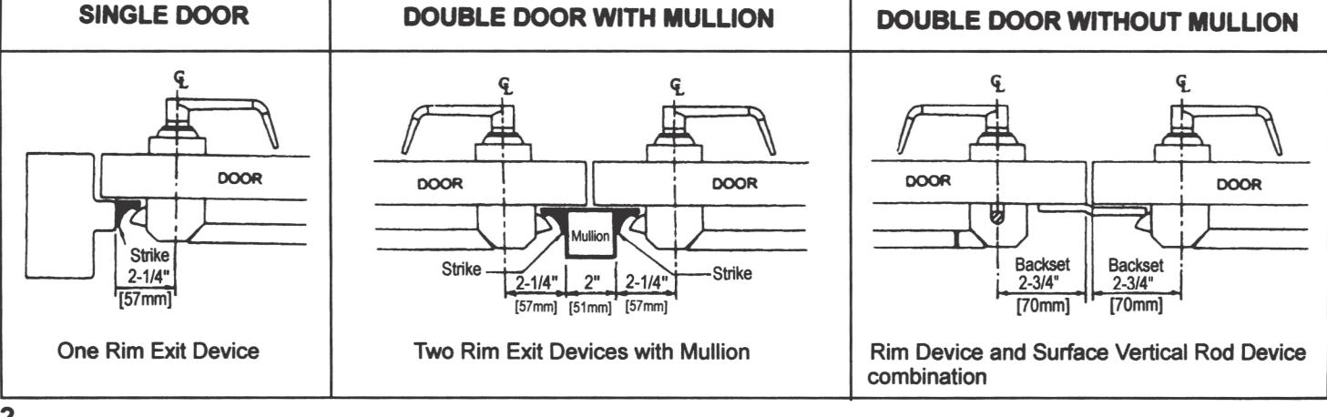
DOOR APPLICATIONS
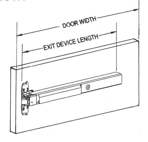
STEP 1: MEASURE AND CUT DEVICE TO LENGTH
The exit device has two sizes: one sized for a 36" door width and one sized for a 48" door width. For 36" or 48" wide doors, no cutting required, skip to next step.
- 1) Measure door opening (door width).
- 2) Measure exit device length NOT including end cap.
- 3) Exit device length must be 4" shorter than door width.
- 4) For other door widths, cut exit device to appropriate length. Be sure the end of device body and cover plate are flush before cutting.
Note: Device must be cut square for proper end cap fit.
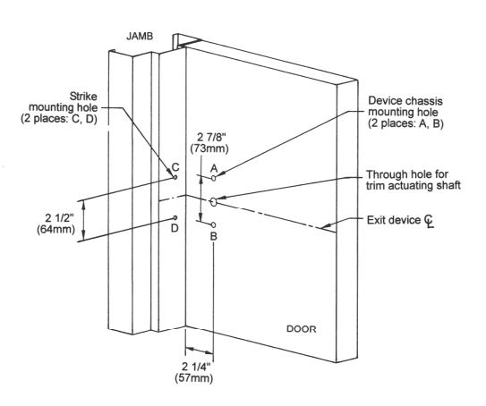
STEP 2 · MARK AND DRILL MOUNTING HOLES
- 1) Mark center line of exit device by drawing a line across the door and stop 40" above finished floor as shown at right.
- 2) Fold or apply template and align center lines on template with center lines on door then mark locations of the exit device 2 mounting holes as shown on template.
- 3) Move template up against stop then mark 2 mounting holes for strike (3 mounting holes for fire rated exit device).
- 4) Drill holes marked on door and jamb or mullion.
STEP 3: INSTALL DEVICE
A. Device Body Installation
- 1) Remove chassis cover from device chassis. Mount device body horizontally to the drilled position by supplied mounting screws or sex bolts.
- 2) If using trim, be sure to line up trim actuating shaft (tailpiece) with cam located on back of device chassis. Details see the installation instructions and template of the trim.
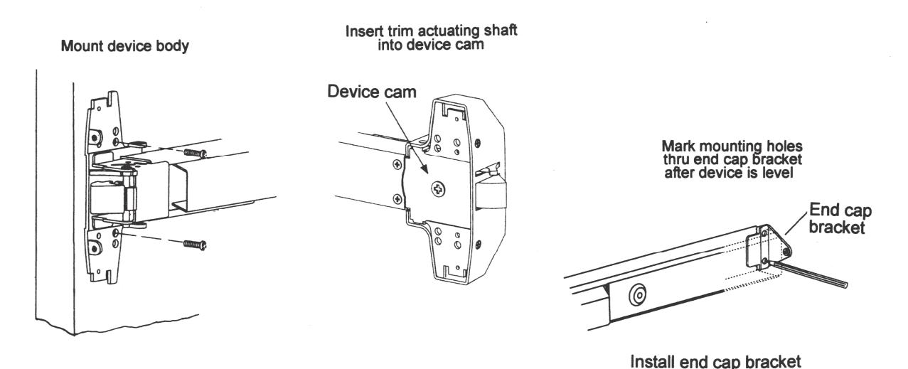
B. End Cap Installation
- 1) Remove end cap from end cap bracket. Mark hole locations by either using template or holding end cap bracket lip into end of device body.
- 2) Mark, drill and tap two mounting holes.
- 3) Install end cap bracket and end cap.
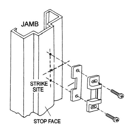
STEP 4: INSTALL STRIKE
- Place strike to the drilled position then using supplied screws to mount it.
- Open and close door to verify latch bolt and dead latch are aligned properly.
- 3) Adjust strike if it is to tight fit or loose fit before tighten screws.
- Once strike is adjusted, secure center screw (for fire rated strike only).
NOTE:
For Panic Rated Rim Exit Device
- 1. 1/8" strike shim is for prepared door with 1/2" (13mm) stop use, which is mounted beneath strike.
- 2. If the stop is 5/8" high, strike shim is not necessary.
For Fire Rated Rim Exit Device - Without strike shim.
STEP 5: INSTALL COVERS
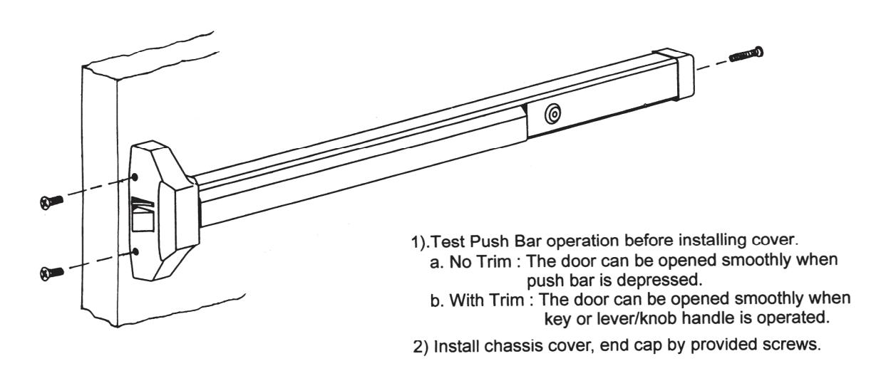
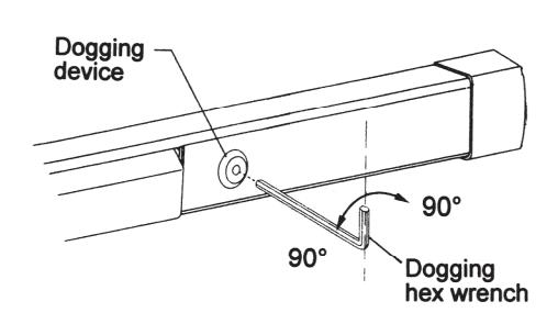
STEP 6: DOG DEVICE
Dogging device during high traffic period of the day will greatly extend life of this device. (A dogging device is not available on fire rated models as fire door must remain closed and latched.)
Dogging:
Depress push bar, insert dogging hex wrench, and turn clockwise 90 degrees. The push bar will remain depressed and the latch will stay retracted.
Release Dogging:
Hold push bar, insert dogging hex wrench, and turn counterclockwise 90 degrees. The push bar will return to the up position and latch will extend to lock door.
4 REV:05,01/2015