Dexter ED1000T Escutheon Lever Wide Stile Trim Installation Instructions 111054
Open the original PDF document
View PDFESCUTCHEON LEVER TRIM INSTALLATION INSTRUCTIONS
Trims covered by these instructions: Cylinder Escutcheon (CE) – Key locks & unlocks lever Blank Escutcheon (BE) – Lever is always operable Night Latch Escutcheon (NL) – Key retracts latch bolt Dummy Escutcheon (DE) – Pull when dogged
DOOR APPLICATIONS
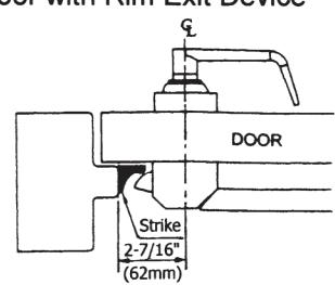
Single Door with Rim Exit Device
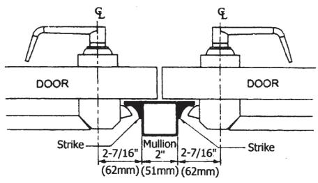
Double Door with Removable Mullion
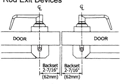
Double Door with One Rim Exit Device and One Surface Vertical Rod Exit Device
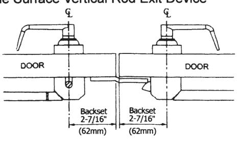
Double Door with Two Surface Vertical Rod Exit Devices
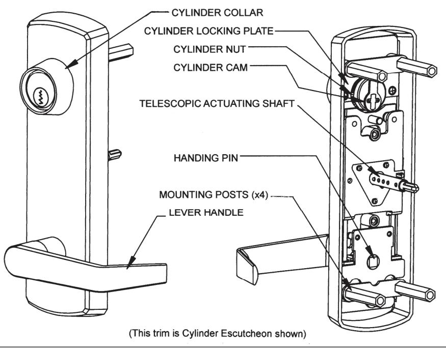
A. SET TRIM HANDING
- Rotate lever handle to the right or left direction to match the desired door handing. (See Fig. 1.) Skip to step 2 for Dummy Trim and Night Latch Trim models.
- Align the handle for the desired door handling then insert the square handling pin into the hub. (See Fig. 2.)
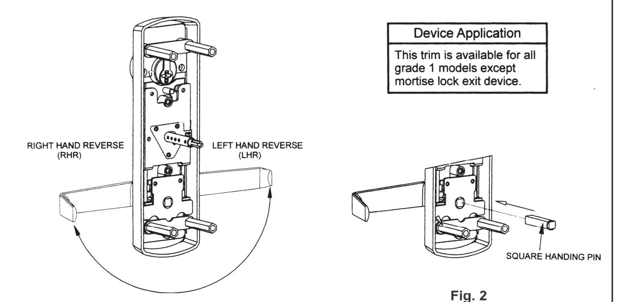
Fig. 1
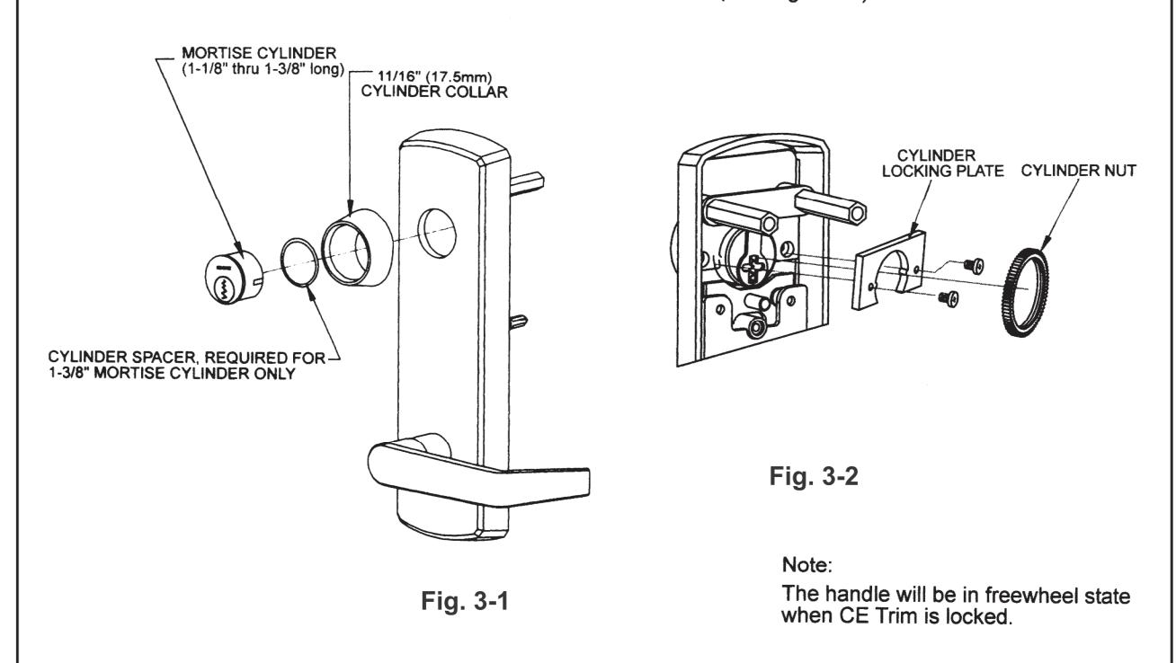
B. INSTALL MORTISE CYLINDER (For CE Trim model only).
- 1. Slide wave washer and cylinder collar onto mortise cylinder body. Then, install mortise cylinder into escutcheon trim with cam up position. (See Fig. 3 -1.)
- 2. Install cylinder locking plate and fasten it with provided screws. Then, screw cylinder nut onto the back of mortise cylinder until secure. (See Fig. 3 2.)
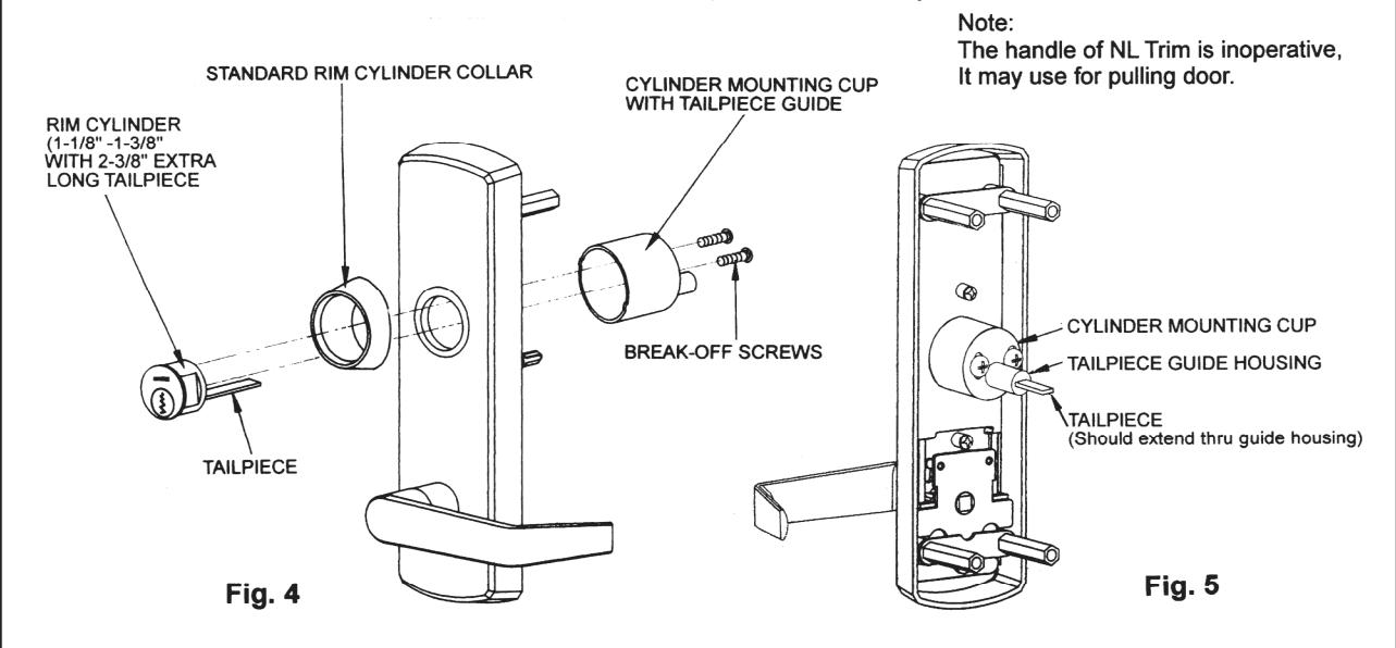
C. INSTALL RIM CYLINDER (For NL Trim model only)
- 1. Check standard length tailpiece on the rim cylinder is long enough or not. If not, use an extra long tailpiece (2-3/8") to replace it.
- 2. Slide cylinder collar onto rim cylinder body.
- 3. Install rim cylinder into escutcheon and align tailpiece with tailpiece guide, and through the cylinder mounting cup. (See Fig. 4.)
- 4. Adjust two break-off screws to eliminate excess length then fasten the rim cylinder. (See Fig. 5.)
- 5. Don't overtighten the screws and verify that tailpiece guide rotates freely.
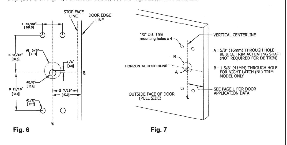
D. MARK AND DRILL MOUNTING HOLES ON DOOR
- Mark horizontal centerline by matching it to exit device centerline, which can be found on the inside face of door.
- Refer to DOOR APPLICATIONS section on page 1 to determine the location of the vertical centerline. This vertical centerline should match exit device vertical centerline located on the inside face of door. Be careful to check the backset that is to door edge or mullion/stop face from the vertical centerline.
- 3. Mark and drill dia 1/2" holes for four mounting posts as shown on template. (See Fig. 6.)
- Mark and drill a 5/8" hole for trim actuating shaft, which mates with exit device. (See A on Fig. 7.) Night Latch Trim model skips this step, Dummy Trim is also not required this step. See exit device instructions for more details.
- 5. Mark and drill a 1-5/8" hole, centered 1/4" (6mm) above horizontal centerline, for Night Latch Trim model only. (See B on Fig. 7.) For further details, see the Night Latch Trim template.
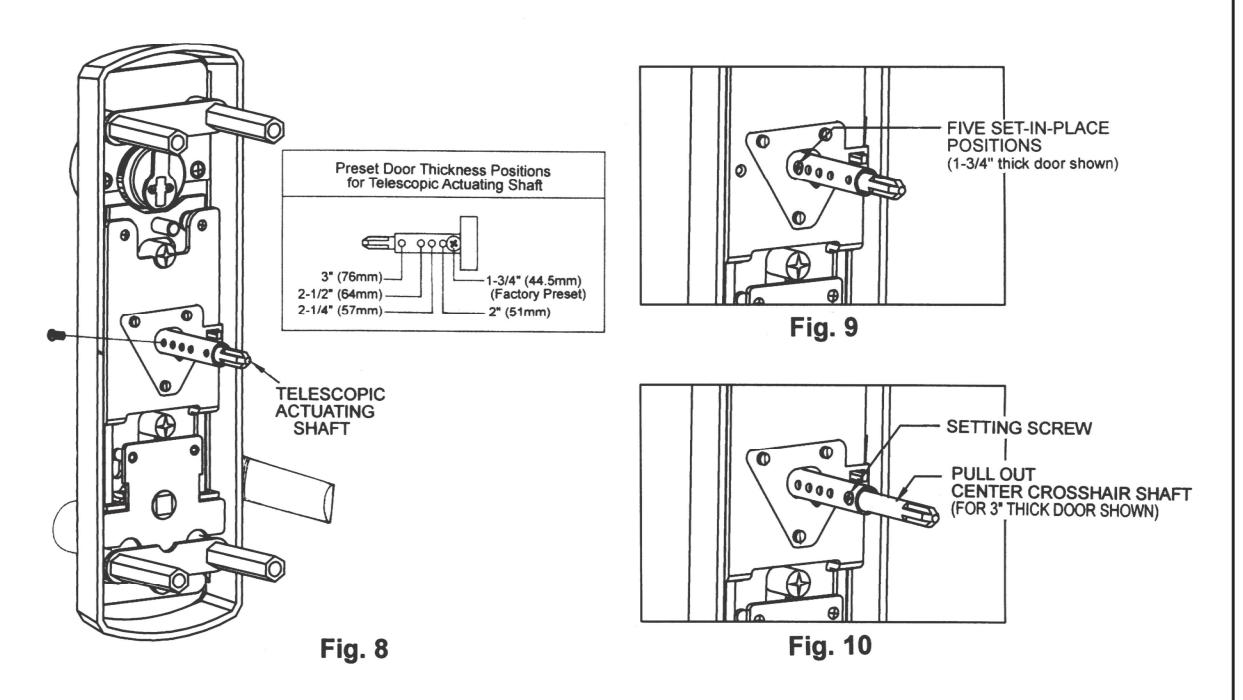
E. ADJUST TELESCOPIC ACTUATING SHAFT (For BE and CE Trim only)
- 1. The trim spindle is a telescopic actuating shaft which is preset at factory for a 1-3/4 " thick door use. (See Fig. 8.) There are 5 set-in-place positions for the following door /shim thickness: 1-3/4 ", 2 ", 2-1/4 ", 2-1/2 ", and 3 ". (See Fig. 9.) For thicker door applications, pull out the center crosshair shaft then set it at appropriate position by a setting screw. (See Fig. 10.)
- 2. Check for proper engagement with exit device in the next step.
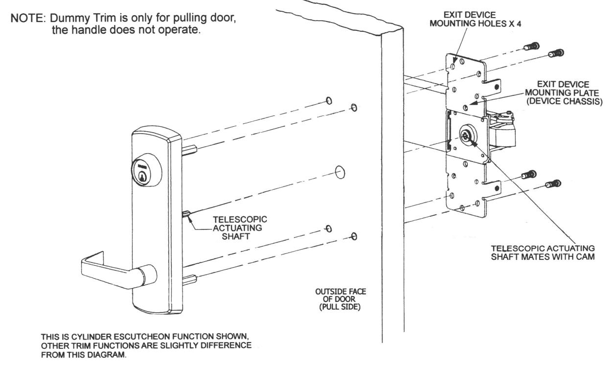
F. INSTALL ESCUTCHEON TRIM
- 1. Insert trim mounting posts and telescopic actuating shaft through door.
- 2. Mate telescopic actuating shaft with cam on back of the exit device.
- 3. Fasten the trim from the four holes on device mounting plate with provided screws.
- 4. Test installation by operating lever handle or key to verify trim.
4 REV : 03,12/2013