Dexter ED1000 SV Panic Fire Installation Instructions 111052
Open the original PDF document
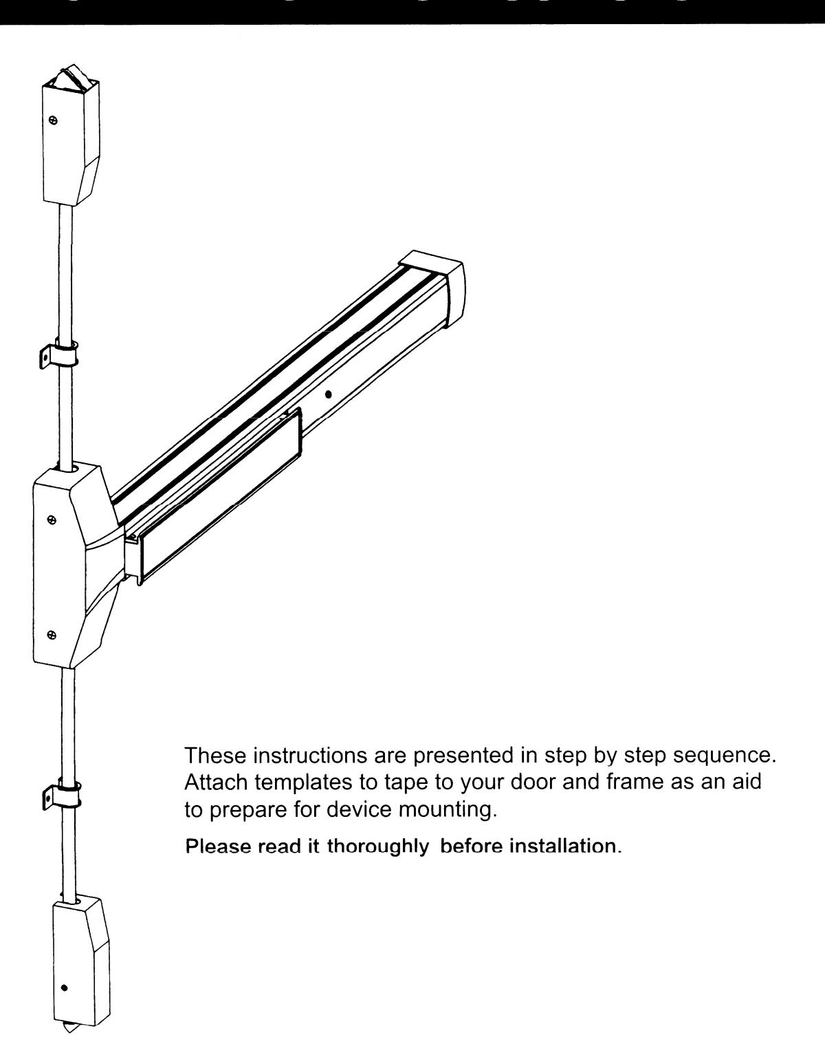
View PDFPANIC / FIRE EXIT SURFACE MOUNTED VERTICAL ROD DEVICES
INSTALLATION INSTRUCTIONS
DESIGNATION OF PARTS
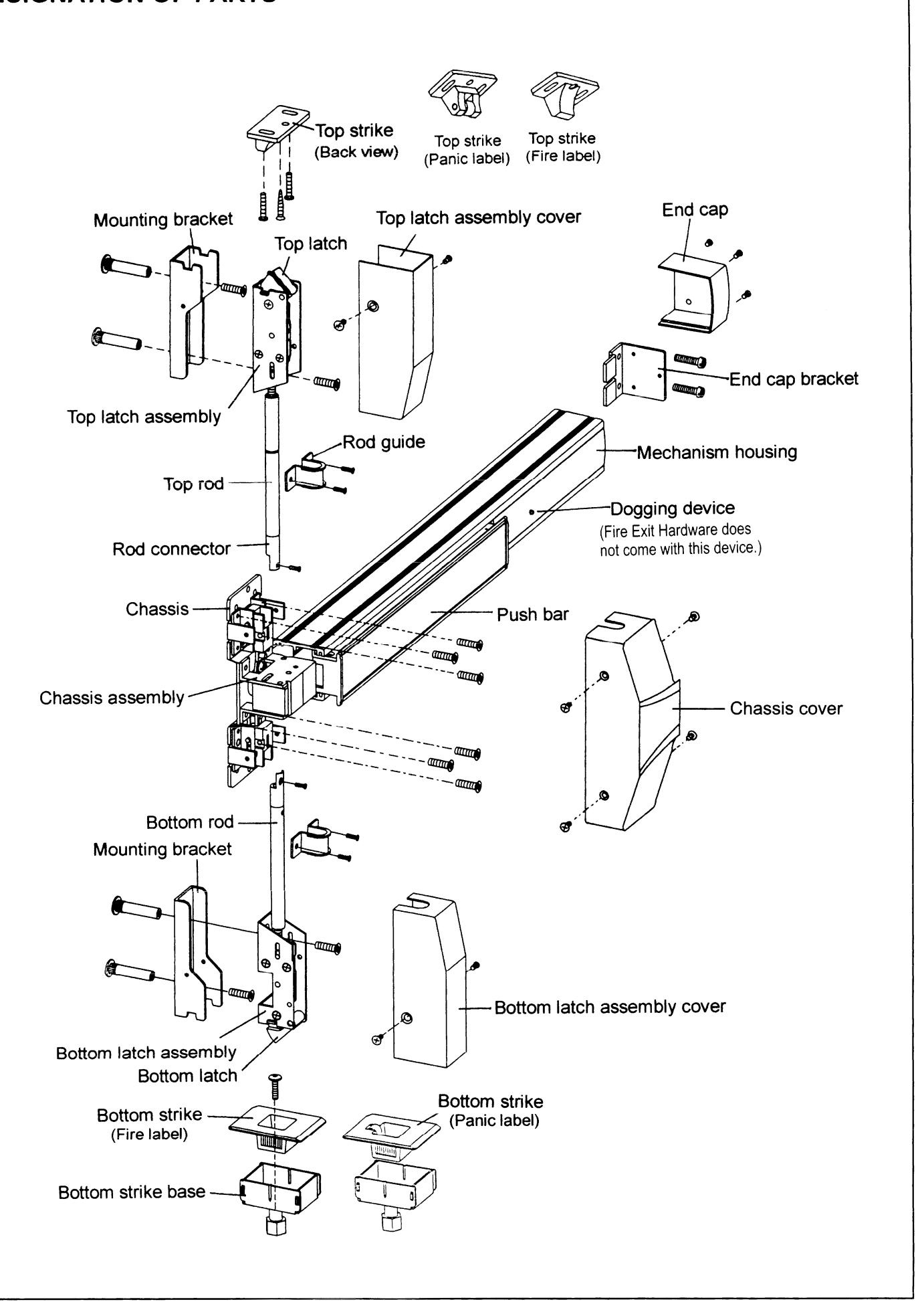
BEFORE INSTALLING THIS EXIT DEVICE:
- 1. Check device to be sure the type is correct for the application.
- 2. Check device for the correct length, finish and outside trim to be used.
STEP 1: PREPARE DOOR
- 1. Mark position of holes on the door by templates. (See Figure 1.)
- 2. Spot and drill all holes as marks on door for device chassis, top & bottom latch mounting brackets, end cap bracket.
- 3. Mortise holes for outside trim if required.
Note:
Any hole drilled from the outside need pilot holes drilled from the inside to ensure good alignment.
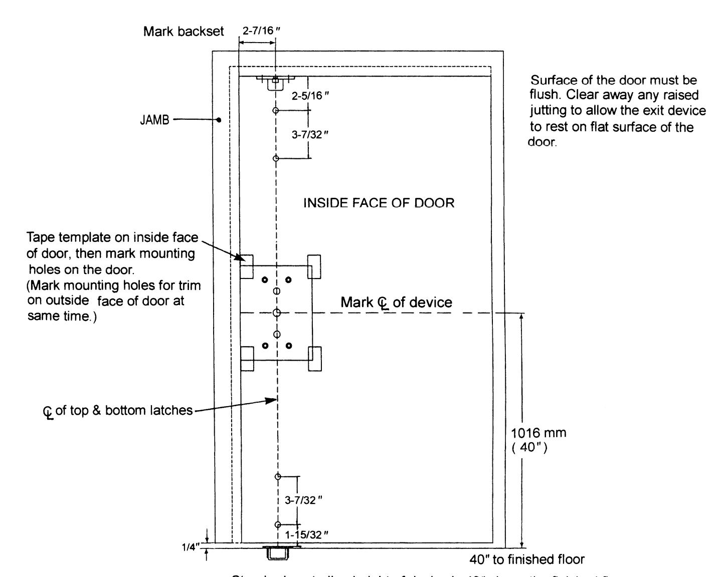
Standard centerline height of device is 40" above the finished floor.
Figure 1
STEP 2: INSTALL BRACKETS, DEVICE & TRIM
- 1. Remove chassis cover from chassis assembly and end cap from end cap bracket.
- 2. Cut the length if required.
For user information: this model device has 2 different lengths.
For use on 3' wide door device = Approx. 33"
For use on 4' wide door device = Approx. 44"
The lengths of devices are precut for 36" and 48" wide door use, no additional cutting is necessary. If narrow door installation is needed, cut device "A" portion to door width minus 4" to fit properly.
Note:
If cutting is necessary, device must be cut plain and clean all burrs for proper end cap fit
- 3. Mounting exit device horizontally to the drilled position on the door securely by supplied screws, and bolt device chassis to trim or sex bolts if using (see the trim installation instructions).
- 4. If using a knob or lever trim, be sure to line up the trim actuating shaft with the device cam which is located on back of the exit device. (Refer to View "+" for cam description.)
- Insert end cap bracket lip into end of device body, then fasten it with provided screws.
- 6. Remove top and bottom latch covers and mounting brackets from both top and bottom latch assemblies. Install two latch mounting brackets on top and bottom of the door (see Figure 2).
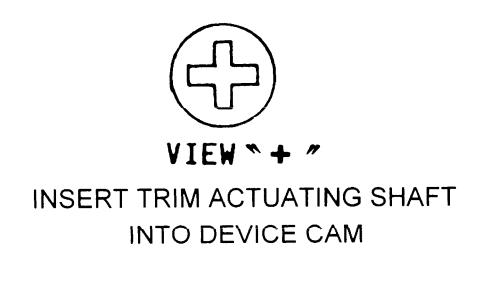
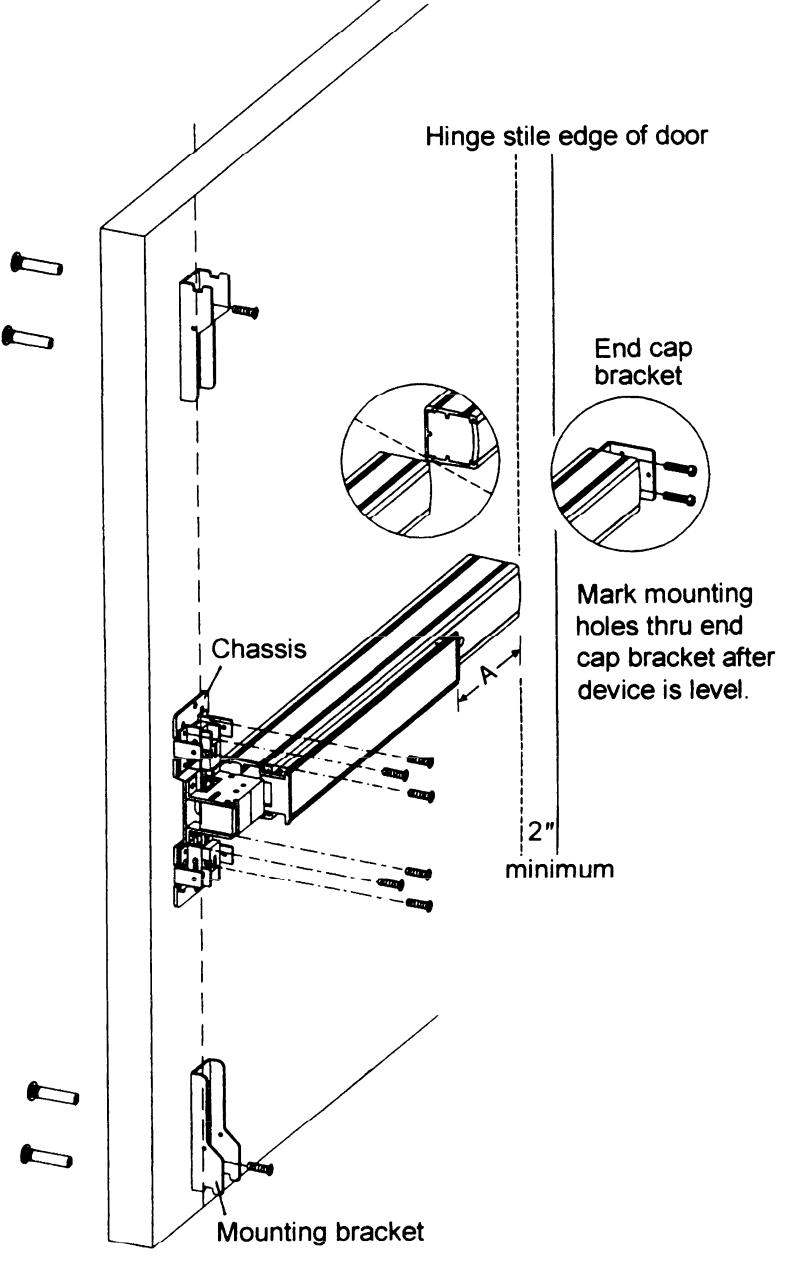
Figure 2
STEP 3: INSTALL BOTTOM ROD AND BOTTOM STRIKE
- 1. Mount bottom latch assembly into mounting bracket. (See Figure 3.)
- 2. Screw the threaded end of bottom rod into bottom latch assembly. (See Figure 4.)
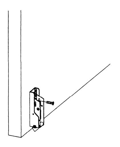
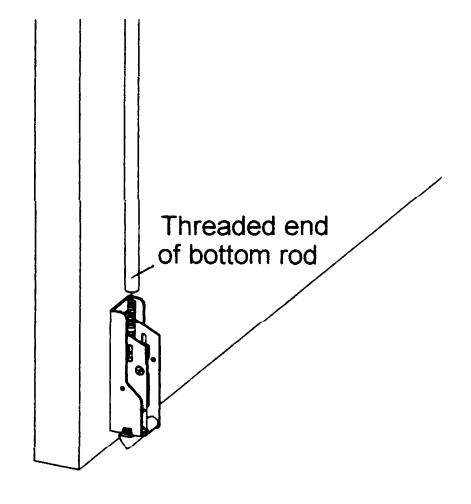
Figure 3
Figure 4
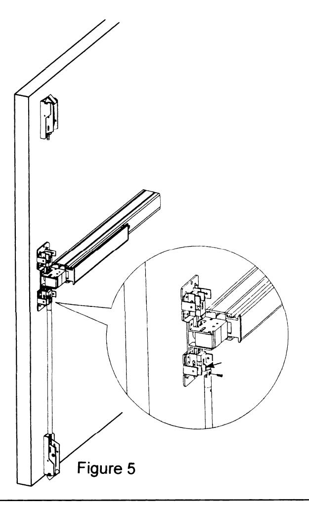
3. Tighten bottom rod on arrow mark position of chassis assembly. (See Figure 5.)
Note: If the hole of bottom rod connector does not match in alignment with the mounting hole, to adjust the overall length by turning rod in or out of latch assembly.
4. Install bottom strike into finished floor or threshold, and be sure to align center line of bottom latch with center line of bottom strike. (See Figure 6.)
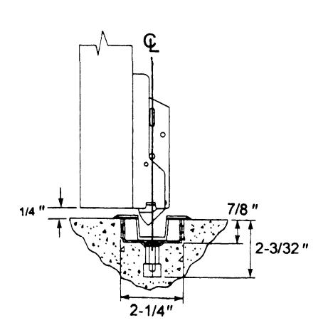
Figure 6
-
5. Depress push bar and release for checking correct installation:
- 5-1 Make sure bottom latch can be held retracted and flush with the edge of door when push bar is depressed.
- 5-2 Check bottom latch bolt has 19/32" (15mm) throw minimum when push bar is released.
STEP 4: INSTALL TOP ROD AND TOP STRIKE
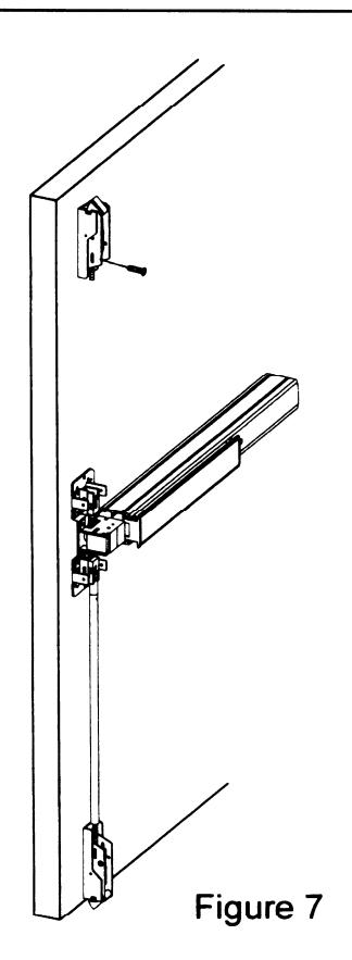
- 1. Mount top latch assembly into mounting bracket. (See Figure 7.)
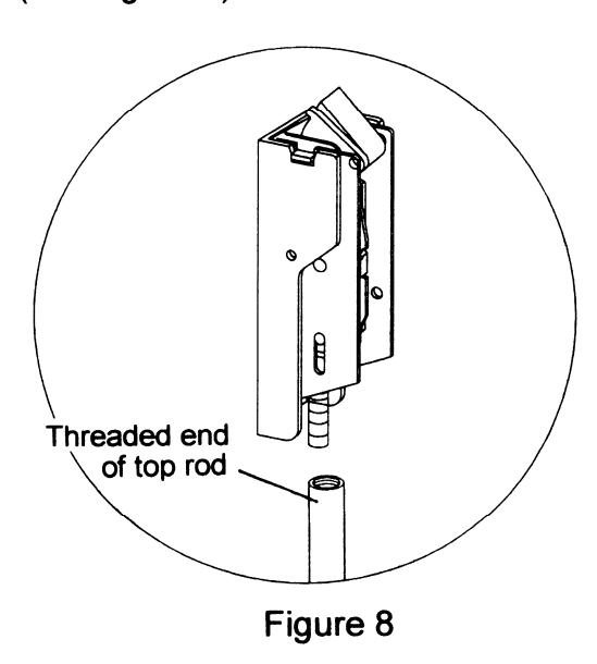
- 2. Screw the threaded end of top rod into top latch assembly completely. (See Figure 8.)
3. Measure and cut the length of top rod. The length of top rod is measured to the edge of rod connector which is going to be fastened on arrow mark position of chassis assembly in next step. Mark the cutting line then cut the excess portion. (See Figure 9.)
4. Insert rod connector into the non-threaded end of top rod and fasten the setting screw securely. (See Figure 10.)
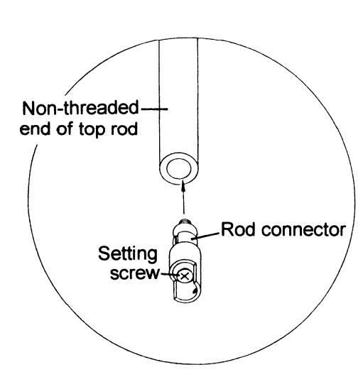
Figure 10
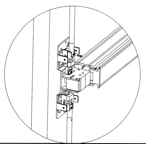
5. Tighten top rod with rod connector onto arrow mark position of chassis assembly. (See Figure 11.)
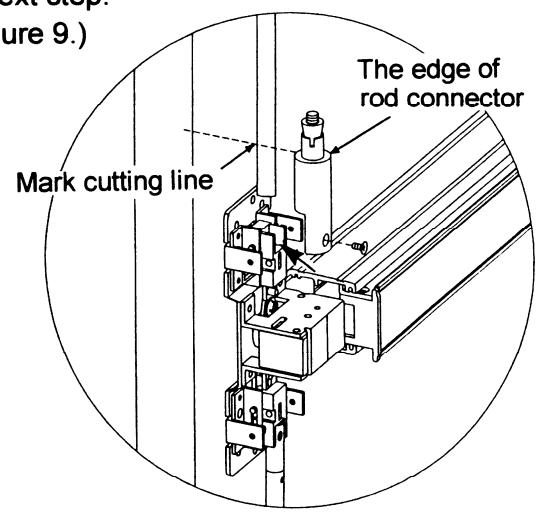
Figure 9
6. Mark mounting holes for top strike on stop face of the top frame as shown by Strike Template (see Figure 12), then fasten with supplied screws (see Figure 13).
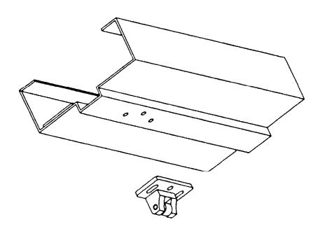
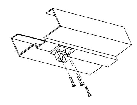
Figure 12
Figure 13
STEP 5: TEST OPERATION
- 1. Depress push bar, top latch should be held retracted. While top latch bolt is retracted, the bottom latch clears floor and bottom strike at same time then door will be opened.
- 2. Release push bar, both top latch bolt and bottom latch bolt should be full extended.
- 3. Check device operation by depressing and releasing push bar for several times to assure final correct installation.
- 4. Repeat device operation by opening and closing door for several times with outside trim to make sure all installation no problem.
- 5. Redo adjustment procedure if either top latch bolt is not held retracted or bottom latch bolt does not clear floor and bottom strike.
STEP 6: INSTALL COVERS
- Before installing covers, make sure and secure latch bolts engagement. Adjust strikes if required.
- 2. Install all device covers and two rod guides in position. (See Figure 14.)
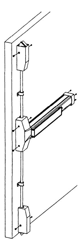
Figure 14
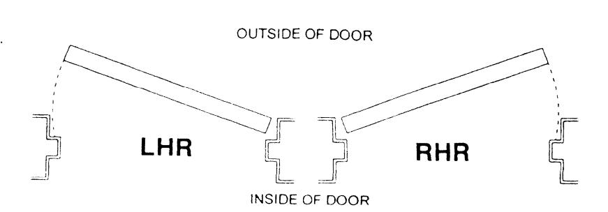
Door Handing
Use the diagram to determine the hand of door.
NOTE:
Dogging device during high traffic period of the day will greatly extend life of this device (panic device only).
Dogging:
Depress push bar, insert dogging wrench and turn clockwise 34°
Depress push bar

The push bar will remain pressed and the latches will keep retracted.
Release dogging:
Depress push bar, insert dogging wrench and turn counter-clockwise 34°
Depress push bar
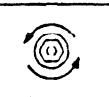
The push bar will return to up position and the latches will project to lock the door.
Dogging wrench