Dexter DCR8000 RWPA Installation Instructions 111046
Open the original PDF document
View PDFDCR8000 SERIES Surface Mounted
Door Closer Non Hold-Open Standard:Back Check Power adjustable 1-4
Installation Instructions for PARALLEL ARM (PUSH SIDE) Mounting
THIS TEMPLATE COVERS PARALLEL ARM INSTALLATIONS TO 180° OPENINGS.
Parallel bracket accessory required and is included.
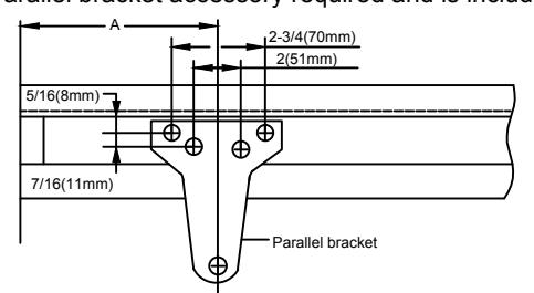
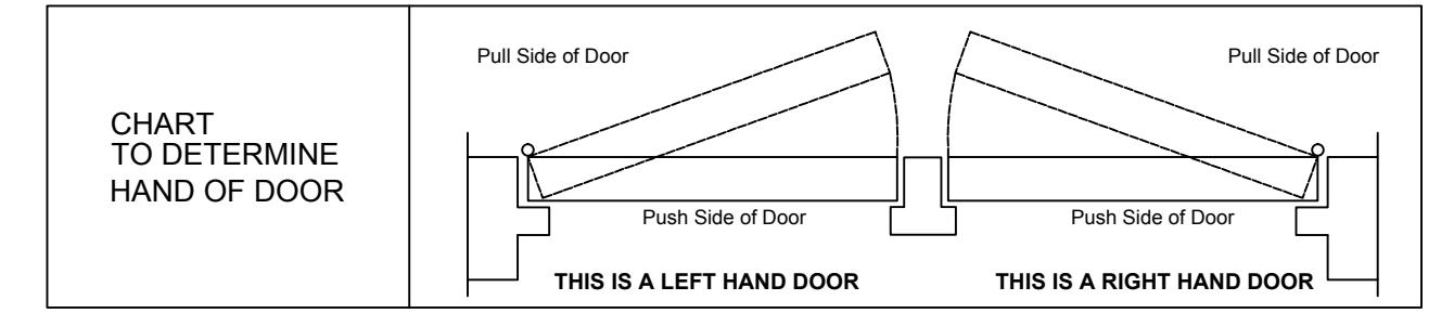
- Left hand door shown
- Right hand door opposite To 120°
- Dimensions are in inches
- Do not scale drawing
| _ | |
|---|---|
| 0 | |
|
DIM.B
IZE:4&5 |
|
|
6 15/16
(176.2mm) |
4 3/4
(120.6mm)
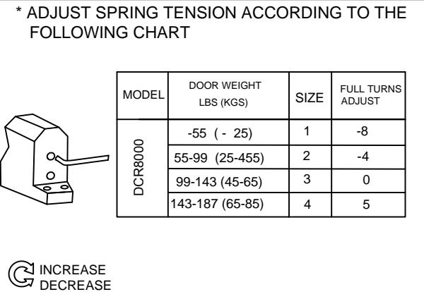
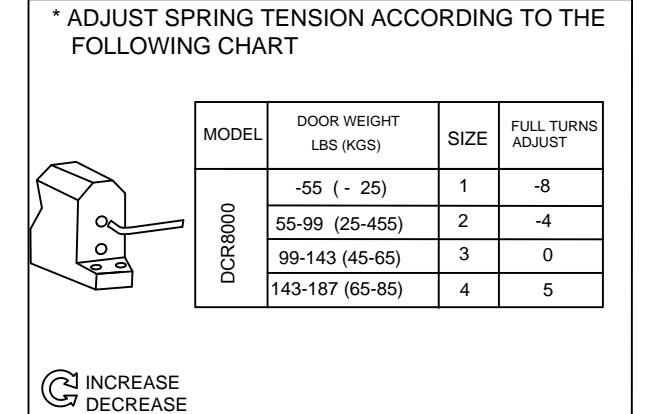
* ADJUST SPRING TENSION ACCORDING TO THE FOLLOWING CHART
| MODEL |
DOOR WEIGHT
LBS (KGS) |
SIZE |
FULL TURNS
ADJUST |
|
| DCR8000 | 0 | -55 ( - 25) | 1 | -8 |
| 55-99 (25-455) | 2 | -4 | ||
| CR | 99-143 (45-65) | 3 | 0 | |
| 143-187 (65-85) | 4 | 5 |
থ increase DECREASE
* NOTE: FACTORY PRESET SIZE 3 MAX. 13 FULL TURNS FROM MIN. SETTING.
INSTALLATION INSTRUCTIONS
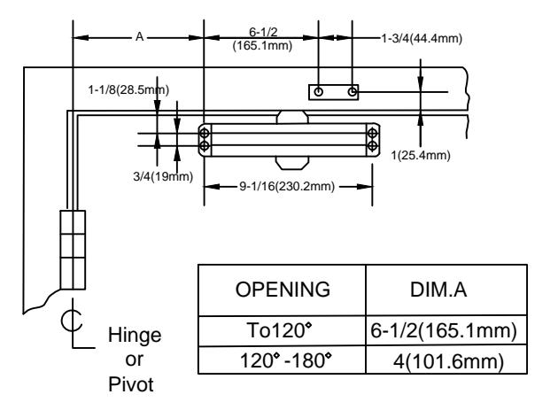
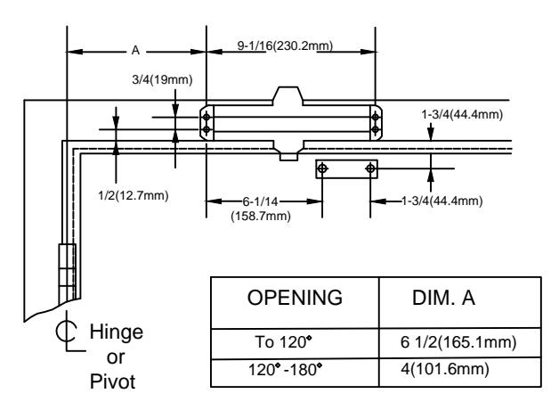
OPENING
120°-180°
SIZE: 4 & 5
(277.8mm)
(222.2mm)
10 7/9
8 3/4
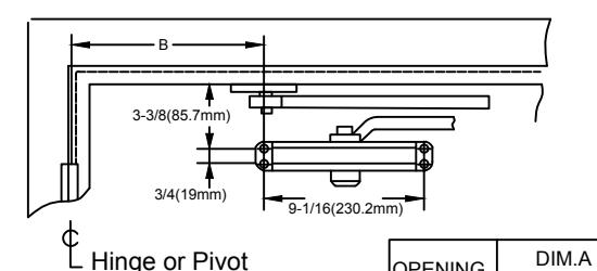
- 1. Select door opening angle and use dimensions shown above, mark four (4) holes on door for door closer and three(3) holes underside of frame for paralled of bracket.
- 2. Drill pilot holes in door and frame to #14 all-purpose screws or drill and tap for 1/4-20 machine screws.
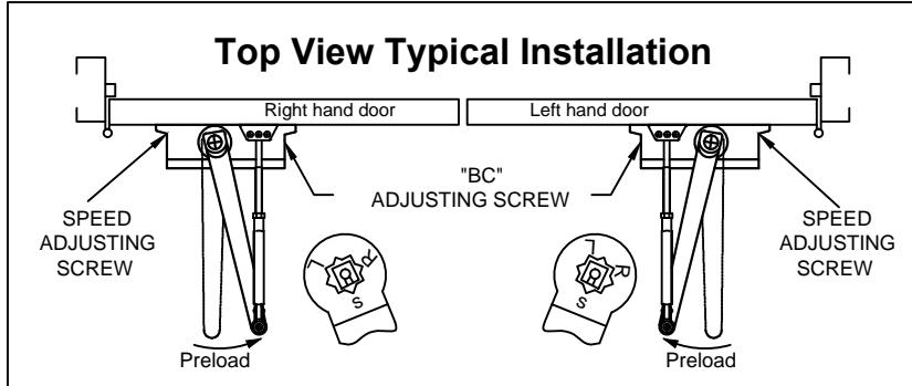
- 3. Mount closer on door using screws provided. SPEED adjusting valve must be positioned away from hinge edge
- 4. Install parallel Arm Bracket to frame using screws provided 5. Using a wrench on the square shaft at bottom of closer, rotate
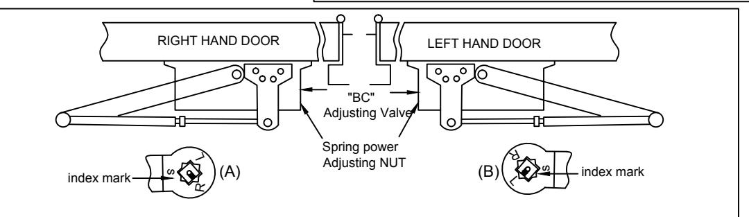
- shaft approximately 45 degree toward hinge of door. Hold and place main arm of shaft on top of closer at proper index mark
- FOR LEFT HAND DOOR "L"(illustration "A"). FOR RIGHT HAND DOOR "L"(illustration "B"). Tighten arm screw with lockwasher securely.
- 6. Remove arm shoe from fore arm and discard. Install ROD end of forearm to bracket using screw/washer assembly provided.
- 7. Adjust length of adjustable forearm so that adjustable forearm is
- 8. Adjust closing speed of door following instructions as shown Page 1
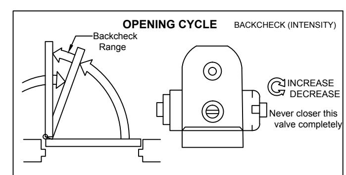
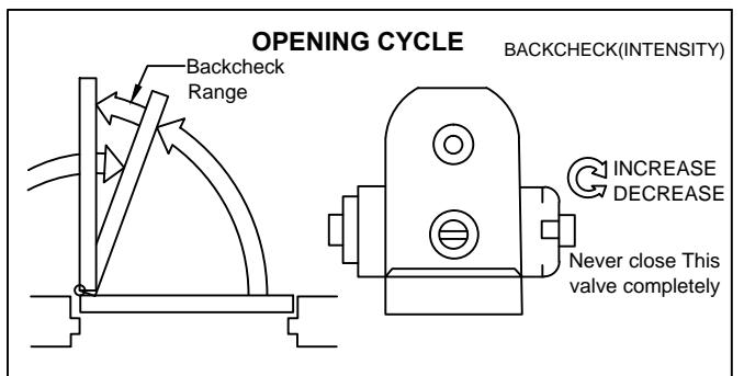
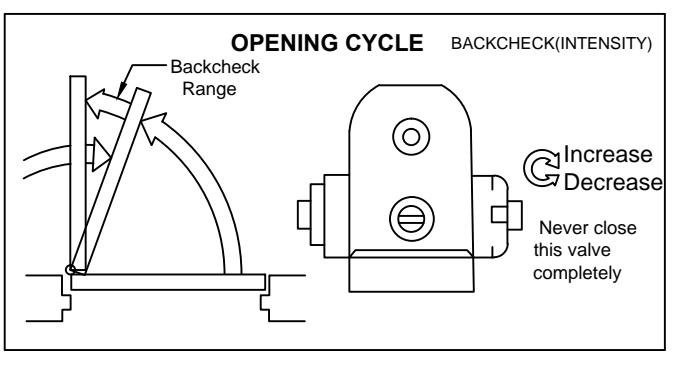
OPENING CYCLE
NOTE: These instructions apply only to closers equipped with backcheck
To increase backcheck intensity, turn valve marked "BC" clockwise. To decrease backcheck intensity, turn valve marked "BC" counter-clockwise.
DCR8000 SERIES Surface Mounted
Door Closer Non Hold-Open Standard:Back Check Power adjustable 1-4

INSTALLATION INSTRUCTIONS
Top Jamb Installation Regular Arm installation Closer installs on PULL/HINGE side of door
Non Hold Open Arm Left Hand Door-RH or Right Hand Reverse -RHR See Page 2
Closer Installs on Frame on PUSH/STOP side of door. Non Hold Open Arm Left Hand Door-RH or Right Hand Reverse -RHR See Page 3
Parallel Arm Installation Closer installs on PUSH/STOP side of door. Non Hold Open Arm Left Hand Door-RH or Right Hand Reverse -RHR See Page 4
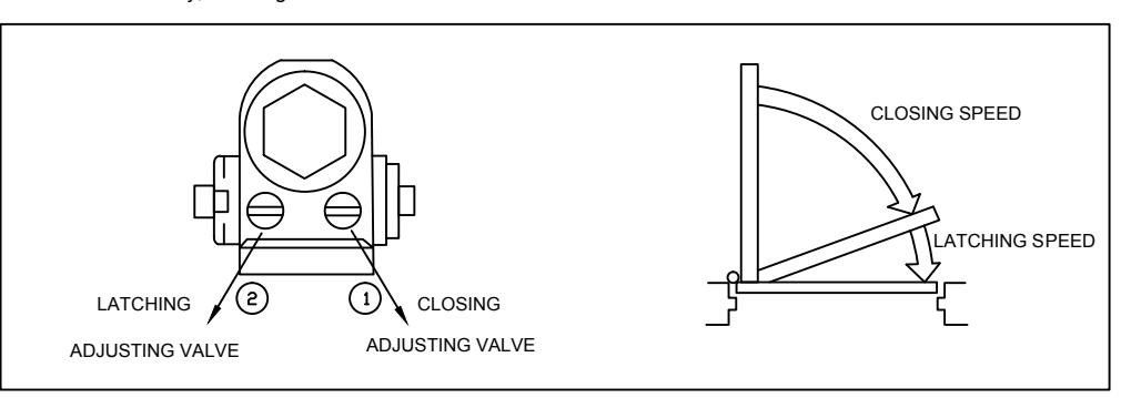
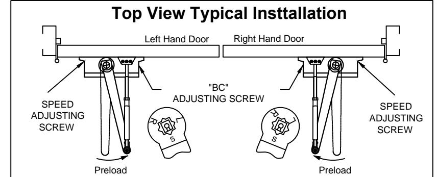
CLOSER ADJUSTMENT
CLOSING CYCLE
NOTE : Closing arcs("CLOSE"and"LATCH") are controlled by two(2) seperate speed adjusting valves. Adjust the CLOSING speed first and then adjust the LATCHING speed.
- 1. "CLOSING" speed adjustment is accomplished by full rotations of the speed adjusting valve.
- -Turn the speed adjusting valve CLOCKWISE for a SLOWER CLOSE arc closing speed
- -Turn the speed adjusting valve COUNTER-CLOCKWISE for a FASTER CLOSE arc closing speed. 2 "LATCH" speed adjustment accomplished by full rotations of the speed adjusting valve.
- -Turn the speed adjusting screw CLOCKWISE for a SLOWER latch are closing speed.
- -Turn the speed sdjusting screw COUNTER-CLOCKWISE for a FASTER Latch arc closing speed.
CAUTION!! Do not turn speed adjusting valve more than two(2) full turns counter-clockwise from its factory set position, as two speed adjusting valves could dislodged from the door closer body, resulting in the loss of internal fluid and failure of the device.
Page: 4 Page: 1
DCR8000 SERIES
Surface Mounted
Door Closer Non Hold-Open Standard:Back Check Power adjustable 1-4
Installation Instructions for REGULAR ARM (PULL SIDE) Mounting
THIS TEMPLATE COVERS REGULAR ARM INSTALLATIONS TO 180° OPENINGS.
- Right hand door shown
- left hand door opposite
- Dimensions are in inches
- Do not scale drawing
OPENING CYCLE
1. Select door opening angle and use dimensions shown above, mark four (4) holes on door for door closer and two (2) holes on frame for arm shoe.
INSTALLATION INSTRUCTIONS
- 2. Drill pilot holes in door and frame for #14 all-purpose screws or drill and tap for 1/4-20 machine screws.
- 3. Install forearm/arm shoe assembly to frame using screws provided.
- 4. Mount closer on door using screws provided . SPEED ADJUSTING VALVE MUST BE POSITIONED TOWARD HINGE EDGE
- 5. Install main arm to top pinion shaft, perpendicular to door as shown below. Secure tightly with arm screw/washer assembly provided.
- 6. Adjust length of forearm so that forearm is perpendcular to frame when assembled to preloaded main arm (Illustration helow) Secure forearm to main arm with screw/washer assembly provided.
- 7. Snap pinion cap over shaft at bottom of closer.
- 8 Adjust closing speed of door, following instructions as shown page 1.
* NOTE: FACTORY PRESET SIZE 3
MAX. 13 FULL TURNS FROM MIN. SETTING.
-
NOTE: these instructions apply only to closers equipped with backcheck
- To increase backcheck intensity, turn valve marked "BC" clockwise
- To decrease backcheck intensity , turn valve marked "BC" counter-clockwise.
DCR8000 SFRIFS Surface Mounted
Door Closer Non Hold-Open Standard:Back Check Power adjustable 1-4
Installation Instructions for TOP JAMB (PUSH SIDE) Mounting
THIS TEMPLATE COVERS TOP JAMB INSTALLATIONS TO 180° OPENINGS
- Left hand door shown
- Right hand door opposite
- Dimensions are in inches
- Do not scale drawing
INSTALLATION INSTRUCTIONS
- 1. Select door opening angle and use dimensions shown above, mark four (4) holes on frame for door closer and two (2) holes on door of arm shoe
- 2. Drill pilot holes in door and frame for #14 all-purpose screws or drill and tap for 1/4-20 machine screws
- 3. Install forearm/arm shoe assembly to door using screws provided.
- 4. Mount closer on frame using screws provided SPEED ADJUSTING VALVE MUST BE POSITIONED TOWARD HINGE EDGE
- 5. Install main arm to top pinion shaft, perpendicular to door as shown below, Secure tightly with arm screw/washer assembly provided.
- 6. Adjust length of forearm so that forearm is perpendicular to frame when assembled to preloaded main arm(illustration below). Secure forearm to main arm with screw/washer assembly provided.
- 7. Snap pinion cap over shaft at bottom of closer.
- 8. Adjust closing speed of door, following instructions: as shown Page1
* NOTE: FACTORY PRESET SIZE 3 MAX. 13 FULL TURNS FROM MIN. SETTING.
OPENING CYCLE
NOTE: These instrucions apply only to closers equipped with backcheck
- To increase backcheck intensity, turn valve marked "BC"
- To decrease backcheck intensity, turn valve marked "BC" counter-clockwise.
Page: 2 Page: 3