Detex ValueSeries EU2W Installation Instructions
Open the original PDF document
View PDFSTEP 4: ROUTING WIRES THROUGH DEVICE Wires can be routed through device or door LOOSEN set screw with 3/32 hex wrench. Do NOT remove. ROUTE wires SLIDE extrusion through extrusion b )away from pushpad assembly NOTE: 1. Detex recommends the power supply to be located within 15 feet of the device. 2. Detex recommends using minimum 20 GA wire for power 3. Current draw: 24VDC = 150 mA RHR 12VDC = 250 mA SHOWN Fail-Secure=Black or Blue spiral tubing Fail-Safe=Red or Yellow spiral tubing CONNECT solenoid and harness wires Rim SVR INSERT excess wires into door TRIM excess wires Installation Continuation: f ) SLIDE extrusion back to pushpad assembly Tighten set screw with 3/32" hex wrench

104849 March 5, 2014
Detex Corporation, 302 Detex Drive, New Braunfels, Texas 78130-3045 (830)629-2900 / 1-800-729-3839 / Fax (830)620-6711 E-MAIL: detex@detex.com INTERNET: www.detex.com
INSTALLATION INSTRUCTIONS FOR "EU2W" LEVER TRIM, 4-1/2" MINIMUM STILE
ELECTRIC UNLOCK: NOTE: Trim is not field reversible.
A DC power source is connected across the brown wires to power the internal solenoid. The solenoid connection is not polarized. The applied voltage will unlock for Fail-Secure and lock for Fail-Safe. Units are color coded as follows:
24 VDC Fail-Secure (Black spiral tubing) p/n 104209-1 24 VDC Fail-Safe (Red spiral tubing) p/n 104209-2 12 VDC Fail-Secure (Blue spiral tubing) p/n 104209-3 12 VDC Fail-Safe (Yellow spiral tubing) p/n 104209-4
STEP 1: PREP TRIM DEVICE Install tailpiece for RIM or SVR
NOTE: Mortise cylinder NOT supplied with trim, but can be ordered separately. Cylinder P/N: 102281-X Cylinder plate P/N: 100754 Short collar included Hex nut P/N: 100572-X P/N: 100783 INSTALL mortise cylinder (A short cylinder collar is supplied for cylinders 1" to 1-1/8" long. For cylinders greater than 1-1/8", order tall collar P/N 100752-X) For Fail Secure Trims: SLIDE locking bar to unlock lever & hold, Then, ROTATE lever as shown in Step b below LOOSEN screw P/N: 102291-108 (e) Install Tailpiece P/N: 101478 TIGHTEN screw (b) ROTATE lever Follow steps a thru f in order
104849
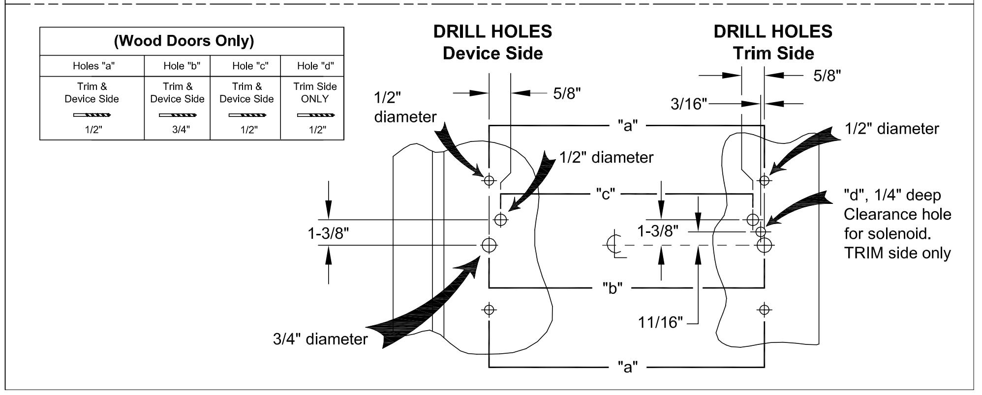
STEP 2a: PREP DOOR (Rim & SVR)
Mark & Drill holes
1/4-20 x 1"
NOTES:
- 1) For a retrofit application, remove device before installing new trim.
- 2) LHR installation shown (Reverse all steps for RHR).
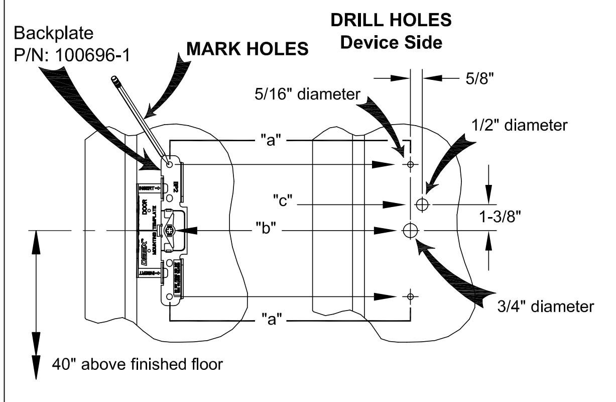
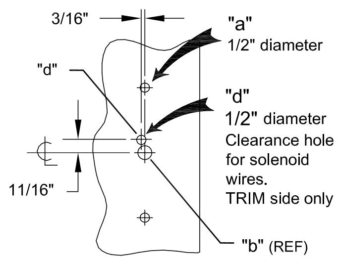
| (Metal Doors Only) | ||||
|---|---|---|---|---|
| Holes "a" | Hole "b" | Hole "c" | Hole "d" | |
|
Device
Side |
Trim
Side |
Trim &
Device Side |
Device
Side ONLY |
Trim Side
ONLY |
| 5/16" | 1/2" | 3/4" | 1/2" | 1/2" |
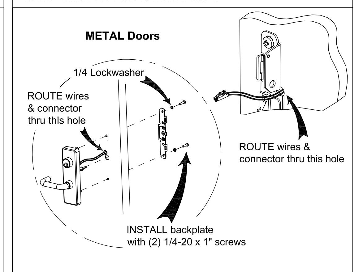
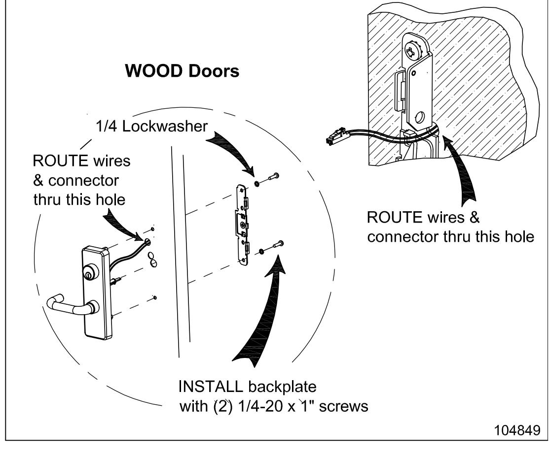
1/4 Lock washer
DRILL HOLES Trim Side
STEP 3a: INSTALL TRIM DEVICE (Rim & SVR) Install TRIM for Rim & SVR Device