Detex Advantex EUxDM Installation Instructions
Open the original PDF document
View PDF

Detex Corporation, 302 Detex Drive, New Braunfels, Texas 78130-3045 830-629-2900 / 800-729-3839 / Fax 800-653-3839 / Text photos only: 830-481-6433 / INTERNET: www.detex.com
INSTALLATION INSTRUCTIONS FOR "EU" LEVER TRIM
Drawing # 104200
| Table of Contents | Page |
|---|---|
| Device parts breakdown view & part numbers | 2 |
| Part numbers (continued) | 3 |
| Prep Trim | 4 |
| Prep Door | 5 |
| Install Trim | 6 |
| Routing Wires through Device | 7 |
Should you have a Question/Problem with your Detex device please call Detex Technical Support from job site at 1-800-729-3839 and choose option 2 on our menu. Please do not return the product to the distributor.
For WARRANTY information, scan code below or go to www.detex.com/warranty
For device installation videos, scan code below or go to www.detex.com/videos

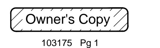

LHR ASSEMBLIES SHOWN
RHR assemblies opposite
| PARTS BREAKDOWN | ||||
|---|---|---|---|---|
| Item | P/N | QTY | Description | |
|
1 106264
106264 101376 101376 101375 101375 101374 101374 |
106264-7 | 1 | LEVER ASSY, Q, 626 | |
| 106264-14 | LEVER ASSY, Q, 693 | |||
| 106264-15 | LEVER ASSY, Q, 695 | |||
| 101376-7 | LEVER ASSY, S, 626 | |||
| 101376-14 | LEVER ASSY, S, 693 | |||
| 101376-15 | LEVER ASSY, S, 695 | |||
| 101375-7 | LEVER ASSY, U, 626 | |||
| 101375-14 | LEVER ASSY, U, 693 | |||
| 101375-15 | LEVER ASSY, U, 695 | |||
| 101374-7 | LEVER ASSY, T, 626 | |||
| 101374-14 | LEVER ASSY, T, 693 | |||
| 101374-15 | LEVER ASSY, T, 695 | |||
| 2 | 106603 | 2 | WASHER, FLAT, 1"x0.02 THK (J LEVER ONLY) | |
| 100851 | 1 | WASHER, FLAT, 1"x0.06 THK (ALL EXCEPT J LEVER) | ||
| 3 | 104210-9 | 1 | ESCUTCHEON ASSY, BP1, EU, 630 FINISH (BP11 FOR EUV) | |
| 4 | 100771 | 1 | STOP, ROTATIONAL | |
| 5 | PP-5305-108 | 1 | SCREW, MACH, 10-24 X 1/2 PFH | |
| 6 | 100777 | 4 | STANDOFF, HEX | |
| 100777-1 | STANDOFF, HEX, CVR (V) | |||
| 7 | 100775 | 1 | WASHER, FLAT | |
PARTS BREAKDOWN Item OTY Description P/N 8 1 CLUTCH SPRING 103047 1 BOTTOM GEAR, WIDE 9 103043 TORQUE PLATE, WIDE 10 1 103044 11 1 KEY, SHEAR PIN, STEEL 103994 WASHER CLUTCH 12 100821 1 SOLENOID ALIGNMENT LOCK, EU 13 104205 1 SCREW, 10-24, CUSTOM 14 102536-1 SOLENOID, 24V, PULL TYPE, FAIL SECURE 104209-1 SOLENOID, 24V, PUSH TYPE, FAIL SAFE 104209-2 15 SOLENOID, 12V, PULL TYPE, FAIL SECURE 104209-3 SOLENOID, 12V, PUSH TYPE, FAIL SAFE 104209-4 16 100766 SPRING, RETURN 17 101509 SPRING, RETURN, HELPER 104212-1 RACK ASSEMBLY, EU, RHR 18 104212-2 RACK ASSEMBLY, EU, LHR 104206-2 COVER PLATE, MACHINED, EU, LHR COVER PLATE, MACHINED, EU, RHR 104206-1 19 106459-2 COVER PLATE, MACHINED, LS, EU, LHR COVER PLATE, MACHINED, LS, EU, RHR 106459-1 PP-5378-106 SCREW, MACH, 8-32 x 3/8 PPH 20 102291-108 SCREW, MACH, 6-32 x 1/2 SEMS, PPH 21 PP-5367-110 SCREW, MACH, 6-32 x 5/8 PPH (LS) 22 104202 TOP GEAR, MACHINED, EU 104213-2 23 LOCK SLIDE ASSY, EU, LHR LOCK SLIDE ASSY, EU, RHR 104213-1 105673-1 LEVER TRIM HARDWARE KIT, RIM, SVR 24KIT 105673-2 LEVER TRIM HARDWARE KIT, MORTISE 105673-3 LEVER TRIM HARDWARE KIT, V 100754 PLATE, CYLINDER POSITION 24A 1 24B 100783 1 NUT. HEXAGON, CYLINDER 24C 101478 SHAFT EXTENSION ASSEMBLY 24D 106694 TAILPIECE ASSEMBLY, D TRIM, CVR UNIVERSAL 24E 103218 SHAFT, INPUT (MORTISE) CYLINDER COLLAR, SHORT 100572-9 100752-9 CYLINDER COLLAR, TALL 26 105964 1 WASHER, WAVE CYLINDER HOUSING, SFIC, MORTISE, 7 PIN, CHROME 103800-626 27 CYLINDER, MORTISE, 5 PIN, CHROME 102281-7-X BRACKET, SOLENOID PLUNGER 28 104207
SCREW, MACH, 8-32x1/4" PPH
BRACKET, SOLENOID
LOCKWASHER, #8
SCREW, MACH, 8-32x3/8" PPH (LS)
ELECTRIC UNLOCK:
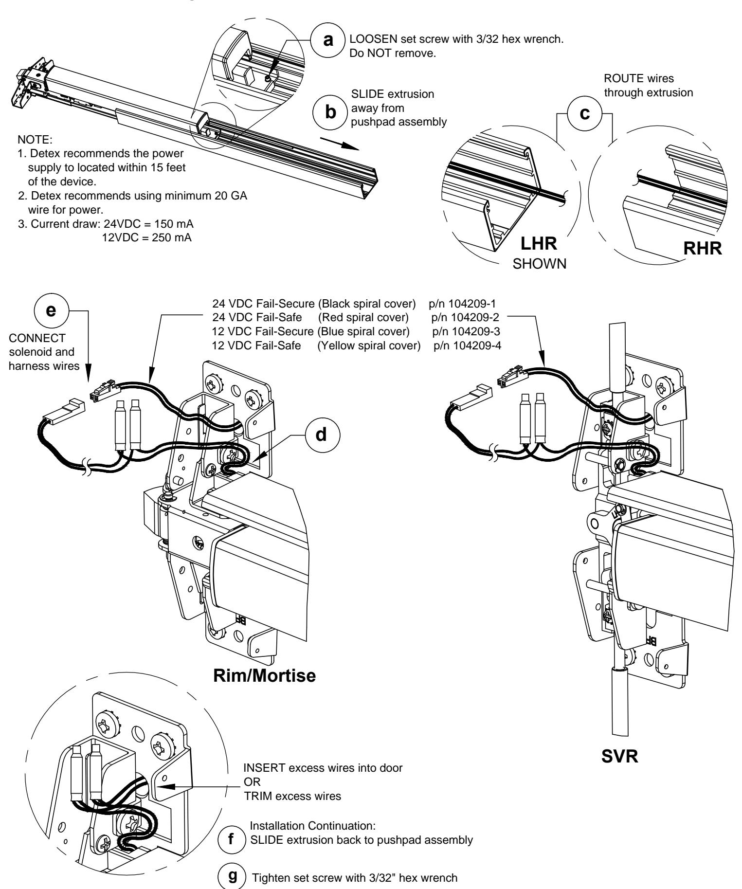
A DC power source is connected across the brown wires to power the internal solenoid. The solenoid connection is not polarized. The applied voltage will unlock for Fail-Secure and lock for Fail-Safe.
Units are color coded as follows:
24 VDC Fail-Secure (Black spiral cover) p/n 104209-1 24 VDC Fail-Safe (Red spiral cover) p/n 104209-2 p/n 104209-3 12 VDC Fail-Secure (Blue spiral cover) 12 VDC Fail-Safe (Yellow spiral cover) p/n 104209-4
FOR ITEM 27 "-X" REFERS TO KEY CODE AA-KK
PP-5378-104
PP-5378-106
PP-5067-8
104208
29
30
31
LHR ASSEMBLIES SHOWN
RHR assemblies have switch assemblies & levers on opposite side NOTE: Assemblies CANNOT be rehanded
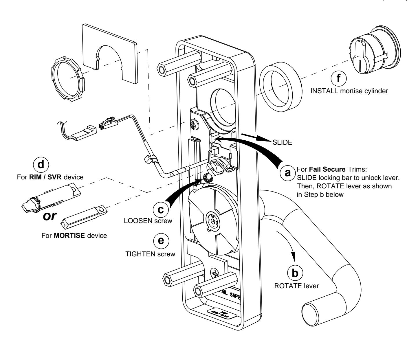
STEP 1: PREP TRIM DEVICE
Install tailpiece for RIM, SVR or input shaft for MORTISE and cylinder
NOTE: Mortise cylinder NOT supplied with trim, but can be ordered separately .
Mortise Cylinder with standard Yale cam required on 08/09 trim (sold separately)
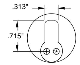
STEP 2a: PREP DOOR (Rim & SVR) DRILL HOLES DRILL HOLES Device Side Trim Side NOTES: 1) For a retrofit application, remove lock and device before installing new trim. 2) LHR installation shown (Reverse all steps for RHR). Ø3/16"enlarge to Ø1/2" Ø5/16" trim side only Ø5/8" DEVICE side only Using the plastic template and backplate, Ø1/2" mark these 5 locations for METAL hole for solenoid wires. 2" and WOOD doors on the DEVICE SIDE Trim side only 11/16" Ø3/4" (ref) door frame thru enlarge to Ø1/2" Ø5/16" trim side only FOR METAL DOORS ONLY thru DRILL HOLES DRILL HOLES Device Side Trim Side 3/16"enlarge to Ø1/2" Ø5/16" trim side only Ø5/8" thru Ø5/8" 40" (ref) thru above Ø1/2" x 1/4" deep finished hole for solenoid floor connector clearance. 2" Trim side only 11/16" Ø3/4" (REF) thru enlarge to Ø1/2" Ø5/16"

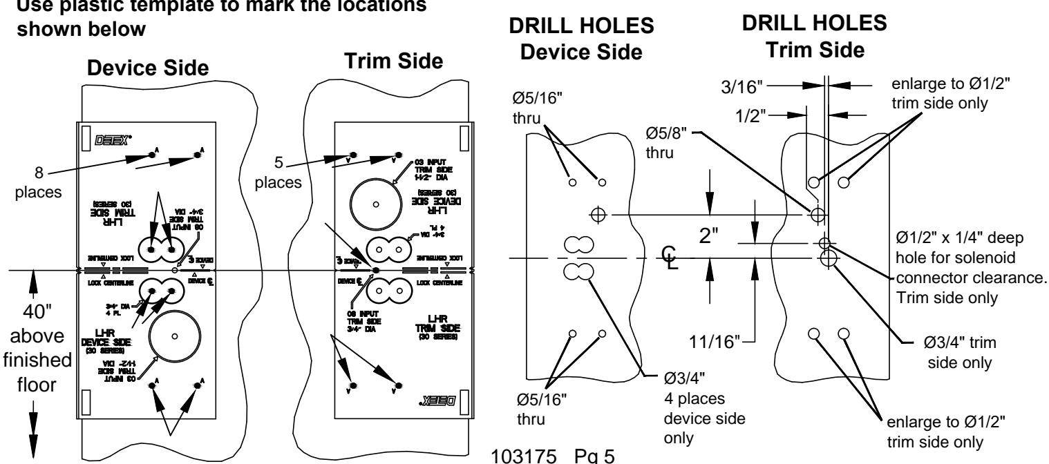
thru
trim side only
FOR WOOD DOORS ONLY
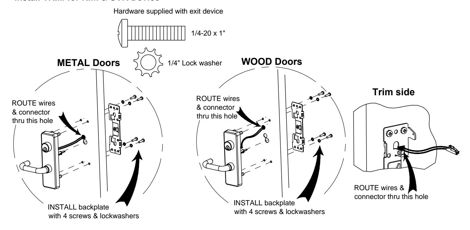
STEP 3a: INSTALL TRIM DEVICE (Rim & SVR)
Install TRIM for Rim & SVR Device
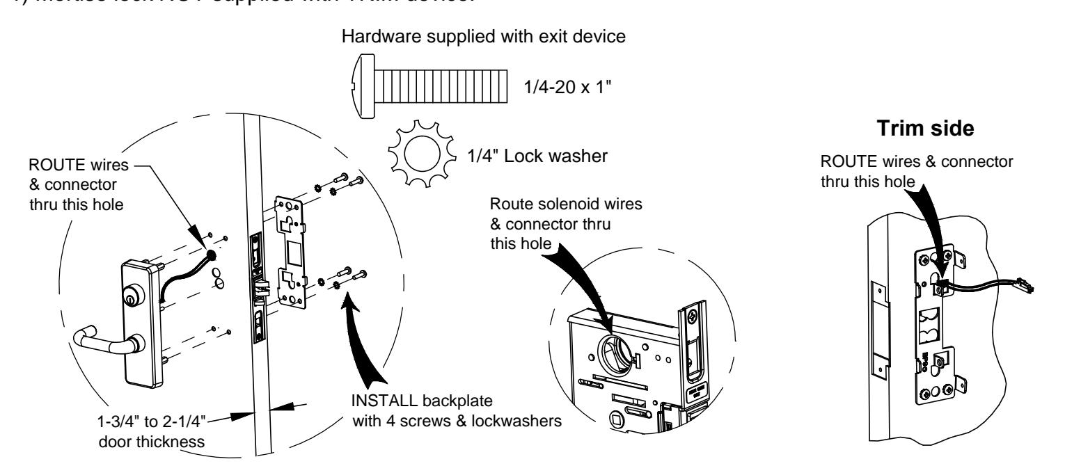
STEP 3b: INSTALL TRIM DEVICE (Mortise)
Install TRIM for Mortise Device
NOTE:
1) Mortise lock NOT supplied with TRIM device.
TRIM INSTALLATION COMPLETE
Continue installation using device instructions.
STEP 4: ROUTING WIRES THROUGH DEVICE
Wires can be routed through device or door