Detex Advantex 14DM Installation Instructions
Open the original PDF document
View PDF

Detex Corporation, 302 Detex Drive, New Braunfels, Texas 78130-3045 830-629-2900 / 800-729-3839 / Fax 800-653-3839 / Text photos only: 830-481-6433 / INTERNET: www.detex.com
INSTALLATION INSTRUCTIONS FOR MORTISE OUTSIDE LEVER TRIMS
Drawing: 101437 (08DM, 08DMT, 08DMU)
101996 (09DM, 09DMT, 09DMU) 101447 (14DM, 14DMT, 14DMU)
| Table of Contents | Page |
|---|---|
| Device parts breakdown view | 2 |
| Device part number list | 3 |
| Prep Trim, Prep Door Trim Side | 4 |
| Prep Door Device Side, Install Mortise Lock & Trim | 5 |
| Re-Handing Lever | 6 |
Should you have a Question/Problem with your Detex device please call Detex Technical Support from job site at 1-800-729-3839 and choose option 2 on our menu. Please do not return the product to the distributor.
For WARRANTY information, scan code below or go to www.detex.com/warranty
For device installation videos, scan code below or go to www.detex.com/videos


Tools Required: Safety Glasses Power Drill Tape Measure Level Pencil Center Punch #2 and #3 Phillips Screw Drivers Drill bits: 5/16" 1/2" 3/4"
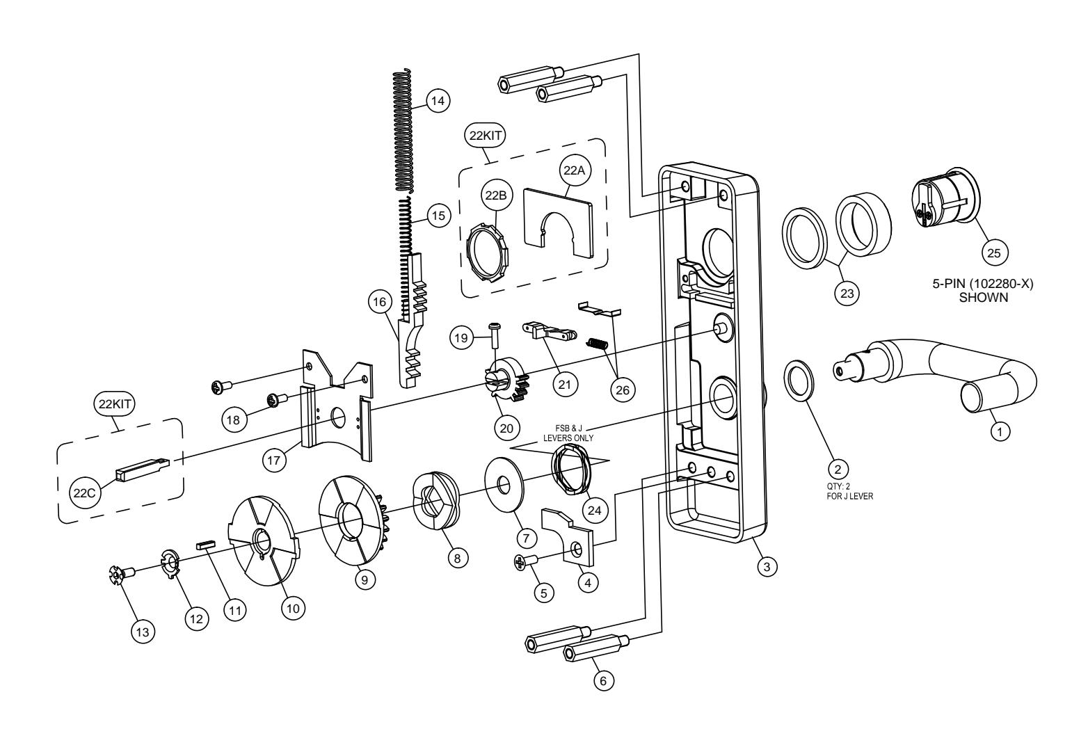
Your particular part or configuration may not be shown: Contact Detex technical support at 800-729-3839 (option 2)
| PARTS BREAKDOWN | |||
|---|---|---|---|
| Item | P/N | QTY | Description |
| 1 1 1 1 1 1 1 1 1 1 1 1 1 1 1 1 1 1 1 | 106264-7 | LEVER ASSY, Q, 626 | |
| 106264-14 | LEVER ASSY, Q, 693 | ||
| 106264-15 | 1 | LEVER ASSY, Q, 695 | |
| 101376-7 | LEVER ASSY, S, 626 | ||
| 101376-14 | 1 | LEVER ASSY, S, 693 | |
| 101376-15 | LEVER ASSY, S, 695 | ||
| 101375-7 | LEVER ASSY, U, 626 | ||
| 101375-14 | LEVER ASSY, U, 693 | ||
| 101375-15 | LEVER ASSY, U, 695 | ||
| 101374-7 | LEVER ASSY, T, 626 | ||
| 101374-14 | LEVER ASSY, T, 693 | ||
| 101374-15 | LEVER ASSY, T, 695 | ||
| 106603 | 2 | WASHER, FLAT, 1"x0.02 THK (J LEVER ONLY) | |
| 2 | 100851 | 1 | WASHER, FLAT, 1"x0.06 THK (ALL EXCEPT J LEVER) |
| 101373-9 | ESCUTCHEON ASSY, 08DM / 09DM, BP1, 630 FINISH | ||
| 3 | 101459-9 | 1 | ESCUTCHEON ASSY, 14DM, BP1, 630 FINISH |
| 4 | 100771 | 1 | STOP, ROTATIONAL |
| 5 | PP-5305-108 | 1 | SCREW, MACH, 10-24 X 1/2 PFH |
| 6 | 100777 | 4 | STANDOFF, HEX |
| 7 | 100775 | 1 | WASHER, FLAT |
| 8 | 103047 | 1 | CLUTCH SPRING |
| 9 | 103043 | 1 | BOTTOM GEAR, WIDE |
| 10 | 103044 | 1 | TORQUE PLATE, WIDE |
| 11 | 103994 | 1 | KEY, SHEAR PIN, STEEL |
| 12 | 100821 | 1 | WASHER CLUTCH |
| 13 | 102536-1 | 1 | SCREW, 10-24, CUSTOM |
| 14 | 100766 | 1 | SPRING, RETURN |
| 15 | 101509 | 1 | SPRING, RETURN, HELPER |
| 16 | 101436 | 1 | RACK ASSEMBLY |
| 17 | 100753 | 1 | COVER PLATE |
| 18 | PP-5378-106 | 2 | SCREW, MACH, 8-32 x 3/8 PPH |
| 19 | PP-5367-108 | 1 | SCREW, MACH, 6-32 x 1/2 PPH |
| 20 | 100762 | 1 | TOP GEAR |
| 21 | 101993 | 1 | LOCK SLIDE |
| 22KIT | 105673-2 | 1 | LEVER TRIM HARDWARE KIT |
| 22A | 100754 | 1 | PLATE, CYLINDER POSITION |
| 22B | 100783 | 1 | NUT, HEXAGON, CYLINDER |
| 22C | 103218 | 1 | SHAFT, INPUT (MORTISE) |
| 23 | 100572-9 | 1 | CYLINDER COLLAR, SHORT |
| 100752-9 | CYLINDER COLLAR, TALL | ||
| 24 | 105964 | 1 | WASHER, WAVE |
| 25 | 103800-626 | 1 | CYLINDER HOUSING, SFIC, MORTISE, 7 PIN, CHROME |
| 102281-7-X | CYLINDER, MORTISE, 5 PIN, CHROME | ||
| 26 | 101997 | 1 | SPRING, COMPRESSION, 09 TRIM (09 function only) |
| 100773 | L | FLAT SPRING LOCKING (08 function only) | |
FOR ITEM 25 "-X" REFERS TO KEY CODE AA-KK
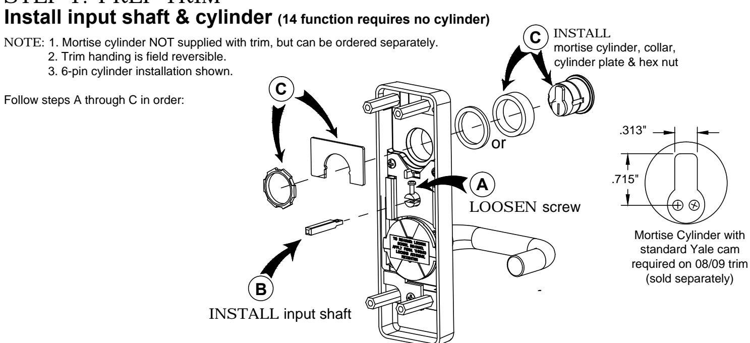
STEP 1: PREP TRIM
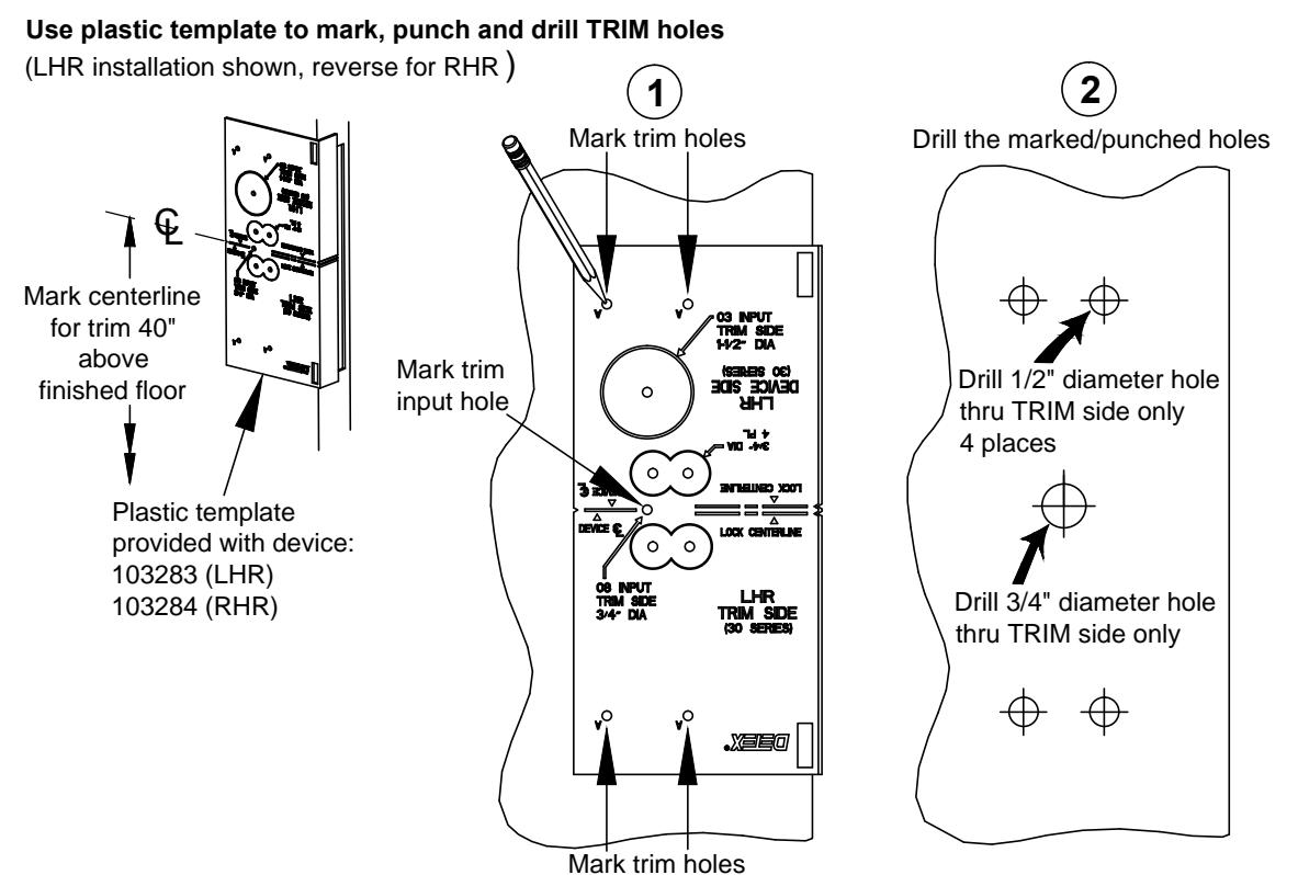
STEP 2: PREP DOOR - Trim Side
Mark and drill holes. (LHR installation shown, reverse for RHR)
STEP 2: PREP DOOR - Mortise - Device Side
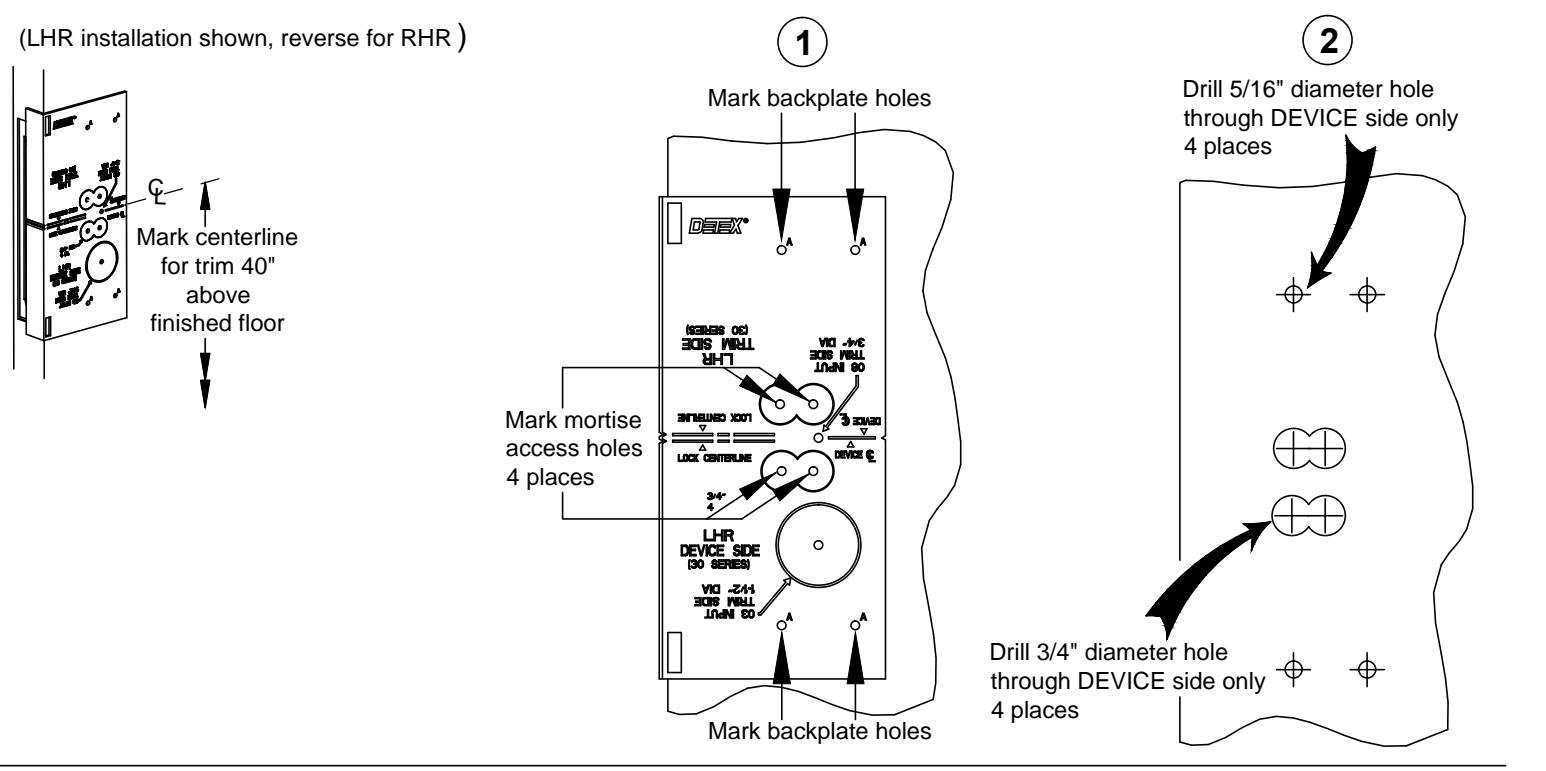
NOTE:
1) For a retrofit application, remove mortise lock (if required) and device before installing new trim.

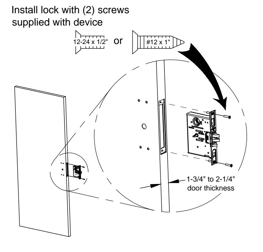
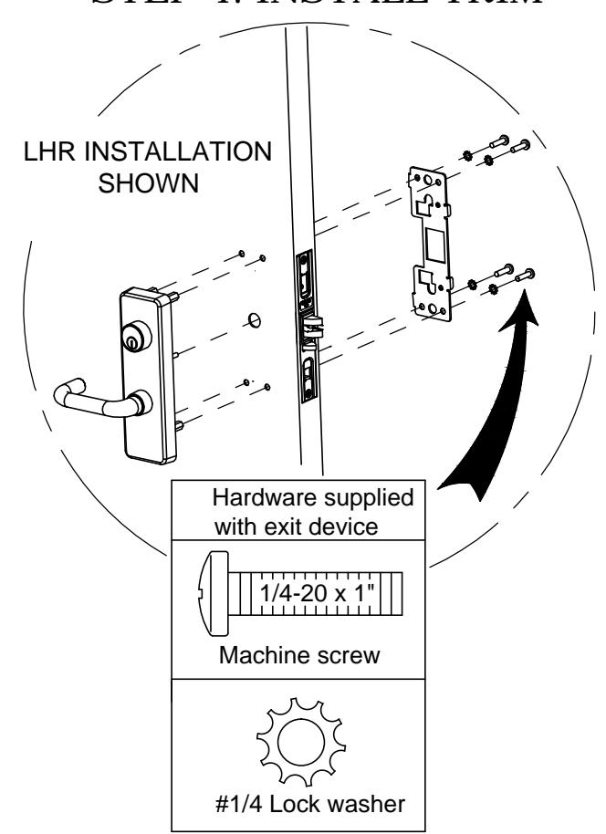
TRIM INSTALLATION COMPLETE Continue installation using device instructions 101349
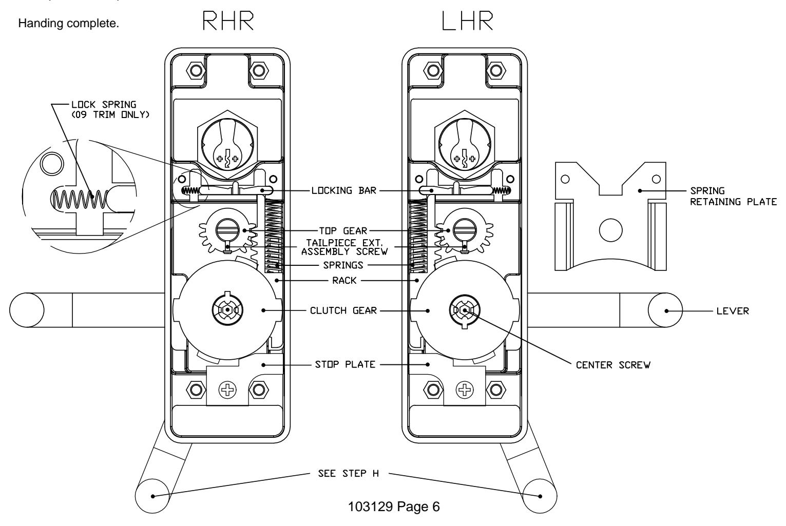
RE-HANDING LEVER (if required)
- A. Remove tailpiece extension assembly screw. Remove tailpiece extension assembly if already installed.
- B. Remove stop plate.
- C. Warning: Springs under pressure! Remove spring retaining plate and carefully remove the springs.
- D. Swith lock spring to opposite side (for 09 function only).
- E. Remove top gear.
- F. Loosen the clutch center screw approximately two (2) turns. Bend locking tab back to disengage with notch.
- G. Slide the locking bar away from the rack (not necessary for 14 function). Remove the rack while rotating the lever.
- H. Continue rotating the lever to the opposite side.
- I. Rotate the lever to the position shown. Partially engage the rack and the clutch gear on the opposite side.
- J. Rotate the lever until the rack is completely seated.
- K. Insert the top gear.
- L. Add permanent thread locking adhesive and tighten the clutch center screw. Bend tab over screw notch so the screw cannot turn.
- M. WARNING: Springs under pressure! Install the springs. Hold the lever in the open position, firmly compressing the springs in place.
- N. While holding the lever in the open position, replace the spring retaining palte and fasten the two (2) screws.
- O. Reverse the stop plate and fasten the screw.
- P. Replace the tailpiece extension and screw.