Design Hardware 1000 Marks M9900 Electric Exit Device Kit Installation Instructions II-E1500-39
Open the original PDF document
View PDF

ELECTRIC EXIT DEVICE KIT INSTALLATION INSTRUCTIONS MOTOR DRIVE ELECTRIC LATCH RETRACTION 1550K-MDH
2-Conductor Wire Run Distance Wire Gauge 70' 22 110' 20 180' 18 280' 16 450' 14 720' 12
II-E1500-39 REV. 10/2019
DESIGN HARDWARE 1000 SERIES
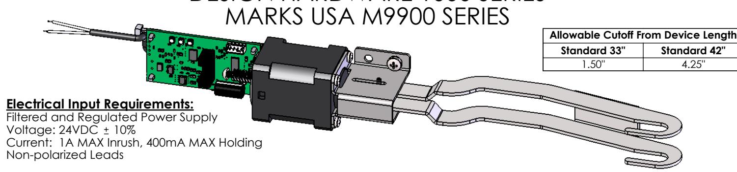
PROVIDES SIMULTANEOUS ELECTRIC LATCH RETRACTION AND DOGGING (PUSH BAR DEPRESSED)
Installation:
- 1. Separate the mechanism case from the baseplate assembly.
- 2. Remove the manual dogging assembly, if present, from the baseplate assembly and discard.
- 3. Skip to step 11 if installing in a 33" device or a 42" device with an 18" push bar.
- 4. Separate the push bar from the baseplate assembly by removing the lower push bar mounting pins.
- 5. Separate the front push bar end cap from the push bar.
- 6. Slide the push bar cover forward to expose the rear push bar end cap mounting screws.
- 7. Replace the rear push bar end cap mounting screws one at a time with the supplied screws to maintain the correct position of the end cap.
- 8. Attach the supplied connecting bracket with connecting pin installed using the supplied locknut.
- 9. Slide the push bar cover back to the original position and attach the front push bar end cap to the push bar.
- 10. Attach the push bar to the baseplate assembly using the lower push bar mounting pins.
- 11. Locate the 1550K-MDH Kit near the holes that secured the manual dogging assembly.
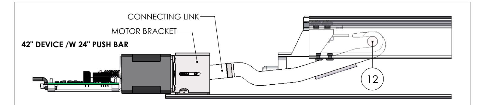
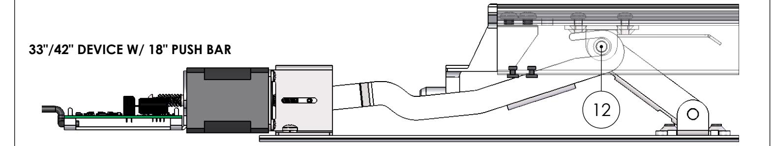
- 12. Attach the connecting link to the installed connecting bracket and pin for the 42" device with 24" push bar or the rear mechanism of the push bar for the 33" device or for the 42" device with 18" push bar.
- 13. Attach the motor bracket to the baseplate assembly using the supplied screws and lockwashers through the holes that secured the manual dogging assembly.
- 14. Attach the mechanism case to the baseplate assembly.
- 15. Install the ratchet clip into the mechanical dogging hole of the slide cover.
- MECHANISM CASE RATCHET CLIP PUSH BAR COVER SUPPLIED CONNECTING PIN SUPPLIED CONNECTING BRACKET SUPPLIED SCREWS SUPPLIED LOCKNUT BASEPLATE ASSEMBLY LOWER PUSH BAR MOUNTING PINS FRONT PUSH BAR END CAP REAR PUSH BAR END CAP END CAP SCREWS 42" DEVICE W/ 24" PUSH BAR 16. Apply the supplied technical assistance labels to the head cover and the end cover. Do not remove any regulatory labels adhered to the device.
2720 CLARK AVE. ~ ST. LOUIS, MO 63103 ~ 1-800-753-5558 ~ www.acsi-inc.com
Motor Drive Electric Latch Retraction Adjustment:
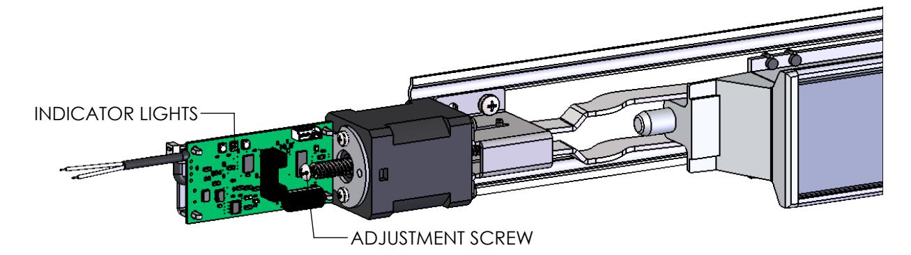
- Verify the device is properly adjusted for mechanical operation. Electric operation should not exceed the mechanical operation or there will be a high risk of damage to the device. We suggest setting the latch retraction under electric operation at 1/16" less than the latch retraction under mechanical operation. Locate the adjustment screw in the rear of the motor assembly. Rotate the adjustment screw clockwise to increase the latch retraction or counterclockwise to decrease the latch retraction.
Onboard Indicator Light Assignments:
Maintain input power to the exit device and check the onboard indicator lights.
Remove input power before attempting a solution.
|
Green
(Power) |
Yellow
(Sensor) |
Red
(Error) |
Indication | Possible Solution |
|---|---|---|---|---|
| Off | Off | Off | No Power. | Connect the wiring between the power supply and the exit device. |
| On | On | Off | Normal Operation. The push bar is retracted to the dogged position and dogged; the latch is retracted by default. The device is allowed 2 attempts. | |
| On | Off | On | Error in operation. The push bar did not retract to the dogged position within 2 attempts. | Rotate the adjustment screw counterclockwise to decrease the latch retraction. |
| On | On | On | Error in operation. Without power being removed, the push bar went from being dogged to unintentionally being extended, and then the push bar did not retract to the dogged position within 2 attempts. | Clear the jam condition manually. |
| On | Blink | On | Error in operation. The push bar did not extend from the dogged position when the power was last removed. The device will not attempt a retraction. | Clear the jam condition manually. |
| On |
Simultaneous
Blink |
Error in operation. The input voltage dropped below the specification during operation. | Decrease the wire run or increase the wire gauge. | |
| On | Alternating Blink | Error in operation. An electronics fault was detected. | An electronics replacement is required. | |