DS1-X Tester Installation Instruction
Open the original PDF document
View PDF

DS1-x
I N S E R T I n s t r u c t i o n s
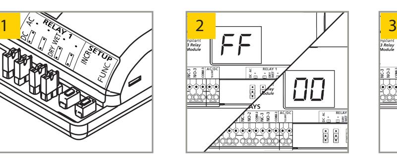
The Command Access DS1-X is a mulit-function Door Sequencing Relay Board
INCLUDED IN KIT DS1-X
Features
- Versatility with 13 programmable logic functions
- Two-button programming combined with dual seven-segment display provides simple setup.
- Two 3-AMP relays and one 1-AMP relay, all with built-in surge suppresion, eliminates the need for external components with installing some electric locking devices.
- Wet output with AC/DC voltage for powering an electric locking device directly from the module.
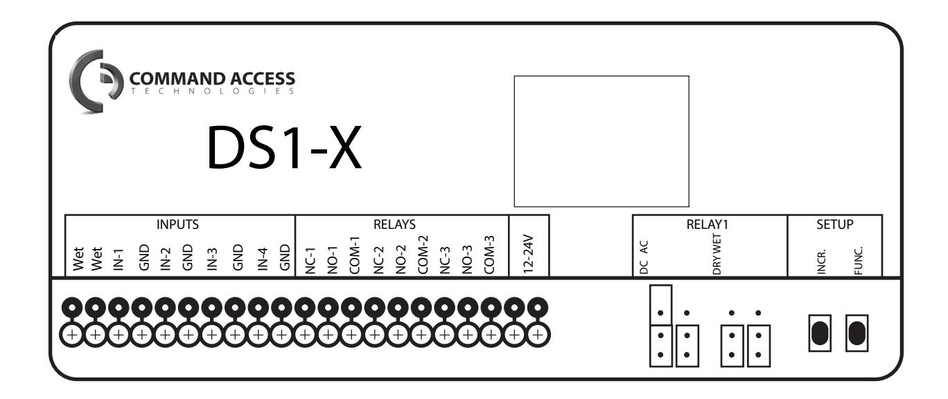
dimensions and specifications

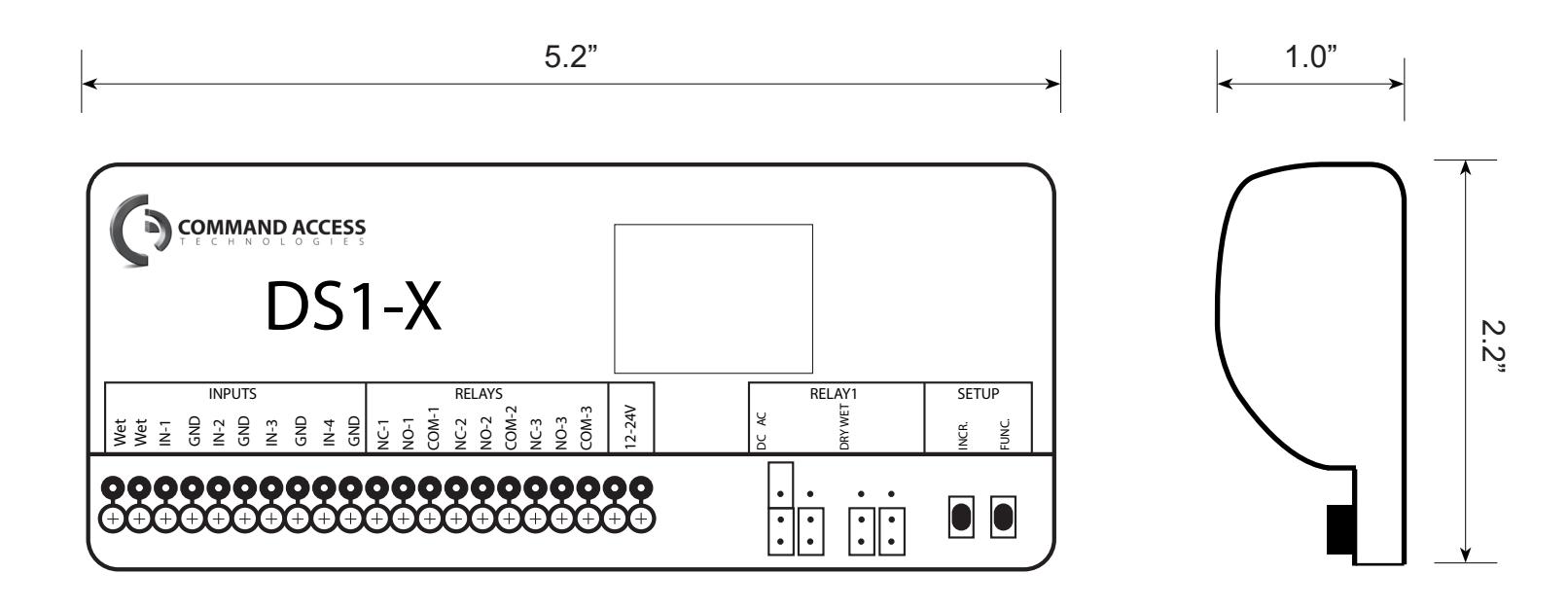
specifications
• Supply Voltage: • Power Consumption: • Relay Hold Time: • Delay Between Relays: 12 - 24 VAC / VDC +/-10% 30 - 130 mA; DRY output up to 60 seconds per relay up to 60 seconds per relay
with 1/4, 1/2 and 3/4 second options
• Input Specification:
Inputs 1, 2, 3, 4 DRY contact
WET Input 5 - 24 VAC / VDC +/-10%
• Contact Rating:
Relay 1 (DRY) 3A @ 24 VAC / 30 VDC
Relay 1 (WET) 1A
Relay 2 Relay 3 3A @ 24 VAC / 30 VDC 1A @ 24 VAC / 30 VDC

PRECAUTIONS

- Shut o all power going to header before attempting any wiring procedures.
- Maintain a clean & safe environment when working in public areas.
- Constantly be aware of pedestrian traffic around the door area.
- Always stop pedestrian traffic through the doorway when performing tests that may result in unexpected reactions by the door. ESD (electrostatic discharge): Circuit boards are vulnerable to damage by electrostatic discharge. Before handling any board
- ensure you dissipate your body's ESD charge.
- Always check placement of all wiring before powering up to ensure that moving door parts will not catch any wires and cause damage to equipment.
- Ensure compliance with all applicable safety standards (i.e. ANSI A156.10) upon completion of installation.
-
DO NOT attempt any internal repair of the components. All repairs and/or component replacements must be performed by Command Access:
- 1. May jeopardize personal safety and may expose one to the risk of electrical shock.
- 2. May adversely aect the safe and reliable performance of the product resulting in a voided warranty.
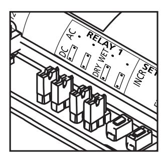
JUMPERS
PRECAUTIONS TO OBSERVE WHEN USING A 'WET' OUTPUT
- Never change the jumper settings when the module has power connected to it or when a load is applied.
- Never allow 2 dierent voltage sources to be connected to the load (electric strike for example) at the same time. This can result in serious damage to equipment.
- Always move both jumpers when changing a jumper set.
- If an EL device is being powered by a separate power source, DO NOT select the 'WET' output option on the DS1-X. If 'WET' is selected, the next activation of the module will send a voltage to the load and if there is already a voltage being applied from another source, the DS1-X and possibly the load will be permanently damaged.
- When using the 'WET' output option on the DS1-X, set all desired switch positions ('WET' 'DRY' and AC DC) before the module is powered and before any loads are applied.
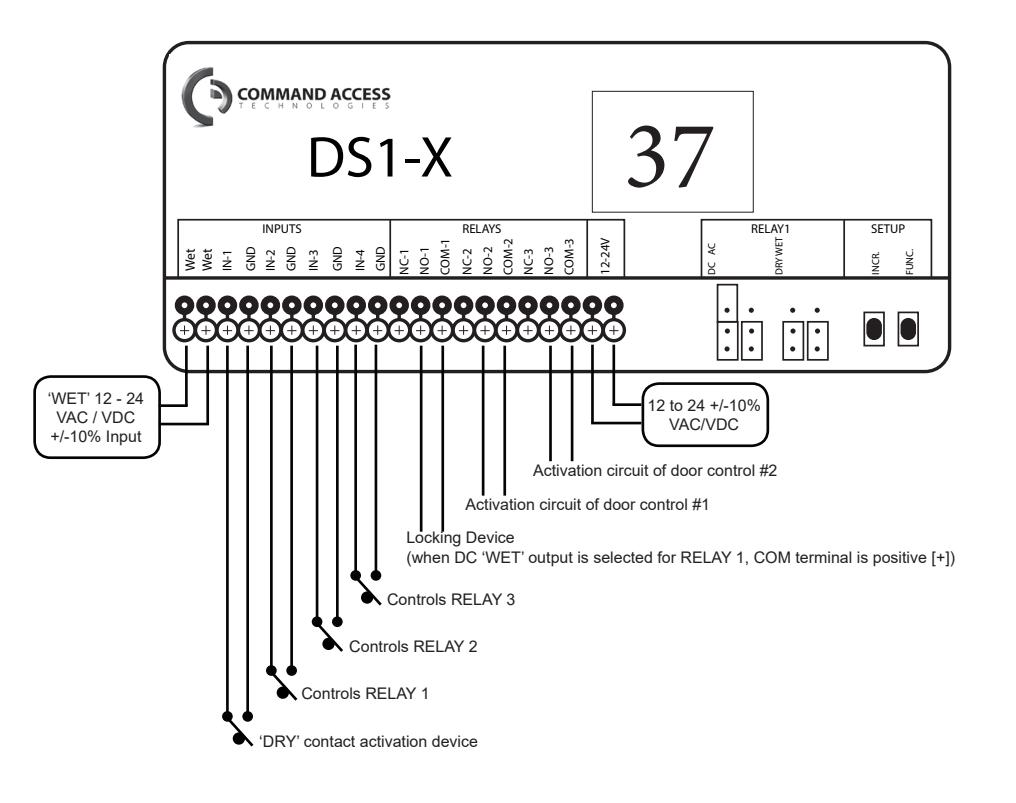
- When DC 'WET' output is selected, COM terminal is positive(+) and the ground(-) is switched between NO and NC.
-
Ensure there is no other voltage connected to the load. Whatever the Input voltage is at the DS1-X, the output will correspond. The following can also be observed:
- 1. If voltage Input at the DS1-X is AC, then output selection can be AC or DC.
- 2. If voltage Input at the DS1-X is DC, then output selection can only be DC.
- 3. The maximum load applied to Relay 1 should never exceed 1A. If more than one device is to be connected, add the consumption values together for a total value. If current is excessive, damage to equipment can result.
- 4. On the DS1-X, the 'WET' output is only available at Relay 1.
- When supplying DS1-X with AC input voltage and selecting Relay 1 output for 'WET' and DC OUTPUT VOLTAGE, note that the resulting DC output will be the rectified AC input voltage and therefore, about 40% higher than the AC input voltage (rms).
CAUTION: Relay 1 'WET' OPTION IS ACTIVE FOR ALL FUNCTIONS!
| RELAY 1 OUTPUT |
DRY/WET JUMPER
2 |
AC OUTPUT VOLTAGE
3 |
DC OUTPUT VOLTAGE
4 |
|---|---|---|---|
| DRY | both jumpers set to DRY | N/A | N/A |
| WET 1 | both jumpers set to WET | both jumpers set to AC | both jumpers set to DC |
NOTES :
- 1. "WET output" allows the DS1-X to supply a voltage output of up to 1 A on relay 1 for powering maglocks or electric strikes directly from the DS1-X. Rating of power supply which powers the DS1-Xmust be at least 1 A.
- 2. Default jumper settings make relay 1 DRY.
- 3. AC voltage only available if DS1-X is powered by AC voltage.
- 4. DC voltage available if DS1X is powered by AC or DC voltage.

WIRING
Each DS1-X function is wired dierently. Please review and follow the appropriate wiring diagram shown for each function.
FUNCTIONS
| FUNCTION | DESCRIPTION | LOGIC |
|---|---|---|
| 10 | timer |
•
activation of relay 1 via trigger of input 1 • reverse logic available |
| 11 | ratchet / latching |
•
ratchet/latching of relay 1 via trigger of input 1 |
| 22 |
2-relay sequencer
+ inhibitor |
•
sequence of relay 1 and relay 2 with inhibiting of input 1 until input 2 , input 3 , or WET input is triggered • activation of input 4 reinhibits input 1 |
| 28 |
2-relay sequencer
+ door position |
•
sequence of relay 1 and relay 2 via trigger of input 1 or WET input • input 2 allows delay to run when open but not when closed |
| 29 | deactivation timer |
•
sequence of relay 1 and relay 2 via trigger of input 1 or WET input • input 2 , once opened after sequence, allows relay 1 to deactivate • input 2 allows delay to run when open but not when closed • input 3 disables sequence, reverse logic available |
| 36 |
3-relay sequencer
+ '1-shot' |
•
sequence of relay 1 and relay 2 and relay 3 via trigger of input 1 or WET input • relay 1 , relay 2 , and relay 3 can be maintained or '1-shot' |
| 37 |
3-relay sequence with
'independent relay' |
•
sequence of relay 1 and relay 2 and relay 3 via trigger of input 1 or WET input • relay 1 , relay 2 , and relay 3 can be 'independent' or sequenced |
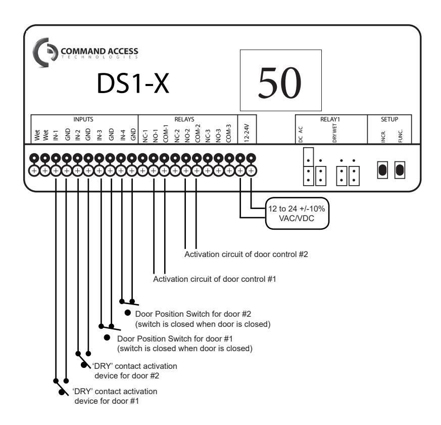
| 50 | interlock timer |
•
interlock of relay 1 and relay 2 via trigger of input 1 and input 2 , respectively |
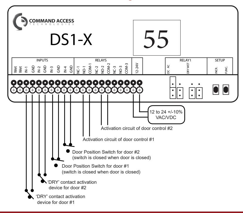
| 55 |
interlock ratchet /
latching |
•
interlock ratchet of relay 1 and relay 2 via trigger of input 1 and input 2 , respectively |
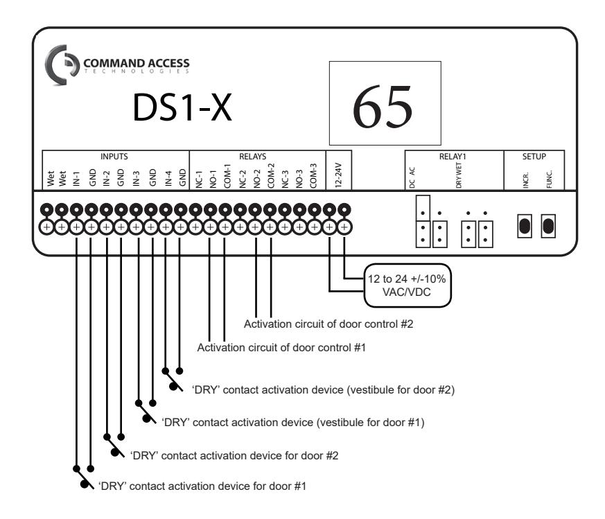
| 65 |
2-way 2-relay
sequence |
•
sequence of relay 1 and relay 2 via trigger of input 1 • sequence of relay 2 and relay 1 via trigger of input 2 • input 3 triggers relay 1 individually, input 4 triggers relay 2 individually |
| NL |
normally locked
restroom |
•
sequence of relay 1 (lock), relay 2 (door), and relay 3 (occupied indicators) for normally locked, single occupancy restrooms |
| NU |
normally unlocked
restroom |
•
sequence of relay 1 (lock), relay 2 (door), and relay 3 (occupied indicators) for normally unlocked, single occupancy restrooms |
| DN |
3-relay sequencer +
'day / night mode' |
•
sequence of relay 1 and relay 2 and relay 3 via trigger of input 1 or WET input • input 2 operation dependent upon input 4 ('day / night mode') |
| 00 | disable |
•
DS1-X disabled • 00 is the default setting and has no assigned function |
PARAMETERS
| PARAMETER | DESCRIPTION | LOGIC | |
|---|---|---|---|
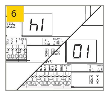
| h1 | relay 1 hold time |
00 - 60 seconds
countdown begins AFTER release of input 1 or WET input |
|
| h2 | relay 2 hold time |
00 - 60 seconds
countdown begins AFTER d1 (delay between relay 1 & relay 2) expires |
|
| h3 | relay 3 hold time |
00 - 60 seconds
countdown begins AFTER d2 (delay between relay 1 & relay 3) expires |
|
| d1 |
delay between
relay 1 & relay 2 |
00 - 60, _1 (1/4), _2 (1/2), _3 (3/4) seconds
delay begins AT activation of input 1 or WET input |
|
| d2 |
delay between
relay 1 & relay 3 |
00 - 60, _1 (1/4), _2 (1/2), _3 (3/4) seconds
delay begins AT activation of input 1 or WET input |
|
| rL | reverse logic |
00 = normal logic
input 1 trigger must be NO and close its contact to trigger |
01 = reverse logic
input 1 trigger must be NC and open its contact to trigger |
| nP | no parameters | no parameters available for selected function | |

PROGRAMMING
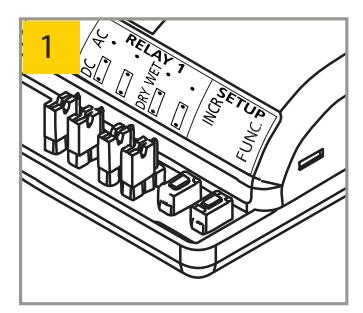
Press and hold INCR + FUNC for 3 seconds.
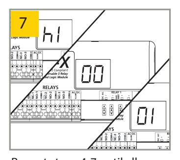
Display will toggle between FF and 00 for 5 seconds. 1,2
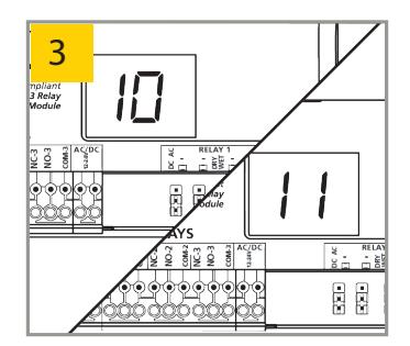
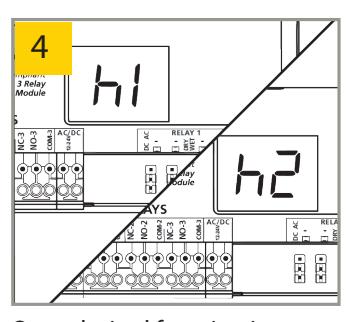
While FF / 00 is displayed, press INCR to cycle through functions.
Once desired function is selected, press FUNC to cycle through parameters.
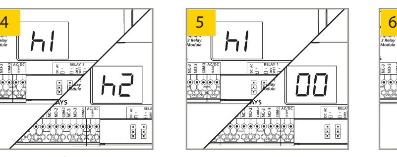
Display will toggle between parameter and its current value for 5 seconds.
Press3 INCR to cycle through parameter's values.
Repeat steps 4-7 until all function parameters are set. Wait 5 seconds for DS1-X to save and display function.

Relay hold time(s) and delay time(s) MUST be set for any relay that is to be utilized.
Ex: For function 36, if using only relay 1, h1 must be set...if using relay 1 and relay 2, h1, h2, and d1 must be set.
NOTES :
- 1. Function 00 disables the DS1-X.
- 2. " nP" means no parameters are applicable for the selected function.
- 3. Pressing and holding INCR will rapid cycle.

PROGRAMMING PARAMETERS
* see page 3 for specific parameter details *
10 – timer
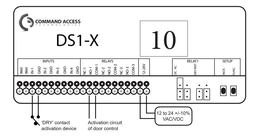
AVAILABLE PARAMETERS:
h1 - relay 1 hold time rL - reverse logic
1. Trigger INPUT 1.
• RELAY 1 will close and hold for time h1.
FUNCTION 10 NOTE: Reverse logic allows for a Normally Closed (NC) INPUT 1.
11 – ratchet / latching
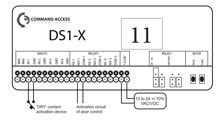
AVAILABLE PARAMETERS:
NONE
-
1. Trigger INPUT 1.
- RELAY 1 will close and hold indefinitely.
-
2. Trigger INPUT 1.
- RELAY 1 will open.
22 – 2-relay sequencer + inhibitor
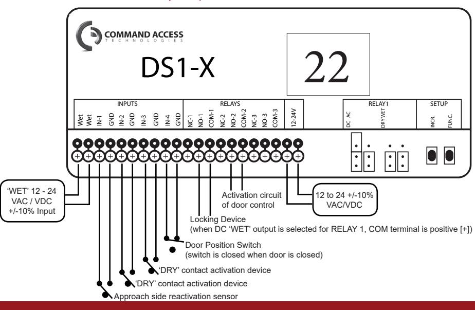
AVAILABLE PARAMETERS:
h1 - relay 1 hold time
h2 - relay 2 hold time
d1 - delay between relays 1 & 2
h1 must be greater than d1 when using an electric lock
-
1. Trigger INPUT 2, 3, or 'WET'.
- RELAY 1 will close and hold for time h1.
- RELAY 2 will close after time delay d1 and hold for time h2.
FUNCTION 22 NOTE: Ensure INPUT 1 does not initiate the sequence and that INPUT 4 is closed when the door is closed.

PROGRAMMING PARAMETERS (cont)
28 – 2-relay sequencer + door position
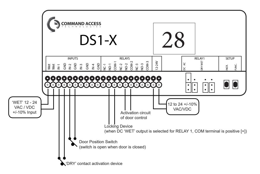
AVAILABLE PARAMETERS:
h1 - relay 1 hold time h2 - relay 2 hold time
d1 - delay between relays 1 & 2
h1 must be greater than d1 when using an electric lock
1. Trigger INPUT 1 or 'WET'.
- RELAY 1 will close and hold for time h1.
- RELAY 2 will close after time delay d1 and hold for time h2.
FUNCTION 28 NOTE: INPUT 2 allows the delay to run when the contact is open but triggers RELAY 2 immediately when the contact is closed.
29 – deactivation timer
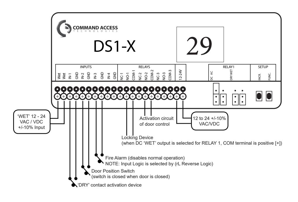
AVAILABLE PARAMETERS:
h1 - relay 1 hold time
h2 - relay 2 hold time
d1 - delay between relays 1 & 2
rL - reverse logic
h1 must be greater than d1 when using an electric lock
1. Trigger INPUT 1 or 'WET'.
- RELAY 1 will close and hold for time h1.
- RELAY 2 will close after time delay d1 and hold for time h2.
FUNCTION 29 NOTE:
INPUT 2 deactivates RELAY 1 once INPUT 2 is opened (and after the sequence has run).
INPUT 2 allows the delay to run when the contact is open, but triggers RELAY 2 immediately when the contact is closed.
INPUT 3 disables the sequence.

PROGRAMMING PARAMETERS (cont)
36 – 3-relay sequencer + '1-shot'
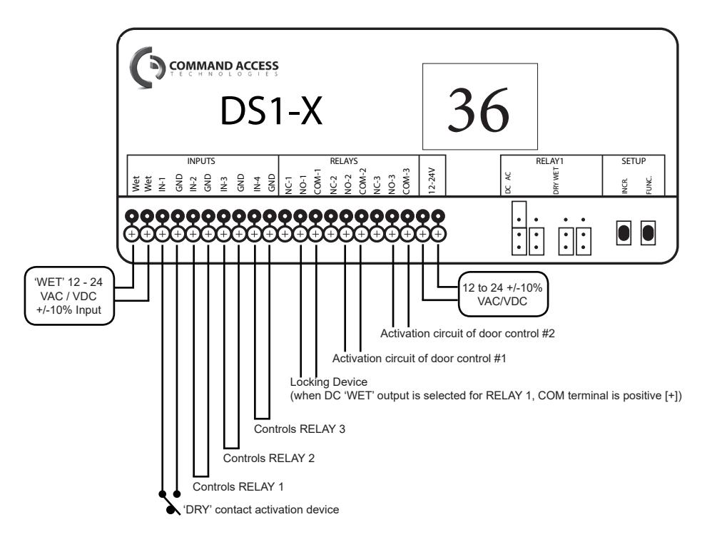
AVAILABLE PARAMETERS:
h1 - relay 1 hold time
h2 - relay 2 hold time
h3 - relay 3 hold time
d1 - delay between relays 1 & 2
d2 - delay between relays 1 & 3
h1 must be greater than d1 when using an electric lock
1. Trigger INPUT 1 or 'WET'.
- RELAY 1 will close and hold for time h1.
- RELAY 2 will close after time delay d1 and hold for time h2.
- RELAY 3 will close after time delay d2 and hold for time h3.
FUNCTION 36 NOTE: If INPUT 1 or 'WET' is maintained, jumping INPUT 2, 3, and/or 4 will allow RELAY 1, 2, and/or 3 (respectively) to close, run the hold time and then open. If no jumpers are set, RELAYS 1, 2, and/ or 3 will close, hold and not time out (open, i.e. 1-shot) until INPUT 1 or 'WET' is released.
37 – 3-relay sequence with 'independent relay'
AVAILABLE PARAMETERS:
h1 - relay 1 hold time
h2 - relay 2 hold time
h3 - relay 3 hold time
d1 - delay between relays 1 & 2
d2 - delay between relays 1 & 3
h1 must be greater than d1 when using an electric lock
1. Trigger INPUT 1 or 'WET'.
- RELAY 1 will close and hold for time h1.
- RELAY 2 will close after time delay d1 and hold for time h2.
- RELAY 3 will close after time delay d2 and hold for time h3.
2. Trigger INPUT 2.
• RELAY 1 will close and hold for time h1.
3. Trigger INPUT 3.
• RELAY 2 will close and hold for time h2.
4. Trigger INPUT 4.
• RELAY 3 will close and hold for time h3.

PROGRAMMING PARAMETERS (cont)
50 – interlock timer
AVAILABLE PARAMETERS:
h1 - relay 1 hold time h2 - relay 2 hold time
1. Trigger INPUT 1.
• RELAY 1 will close and hold for time h1.
2. Trigger INPUT 2.
• RELAY 2 will close and hold for time h2.
FUNCTION 50 NOTE: If INPUT 1 is triggered, INPUT 2 and RELAY 2 will be inhibited until INPUT 3 (door position switch) is closed. Conversely, if INPUT 2 is triggered, INPUT 1 and RELAY 1 will be inhibited until INPUT 4 (door position switch) is closed.
55 – interlock ratchet / latching
AVAILABLE PARAMETERS:
NONE
-
1. Trigger INPUT 1.
- RELAY 1 will close and hold until indefinitely.
-
2. Trigger INPUT 1.
- RELAY 1 will open.
-
3. Trigger INPUT 2.
- RELAY 2 will close and hold indefinitely.
-
4. Trigger INPUT 2.
- RELAY 2 open.
FUNCTION 55 NOTE: If INPUT 1 is triggered, INPUT 2 and RELAY 2 will be inhibited until INPUT 3 (door position switch) is closed. Conversely, if INPUT 2 is triggered, INPUT 1 and RELAY 1 will be inhibited until INPUT 4 (door position switch) is closed.

PROGRAMMING PARAMETERS (cont)
65 – 2-way 2-relay sequence
nL – normally locked restroom
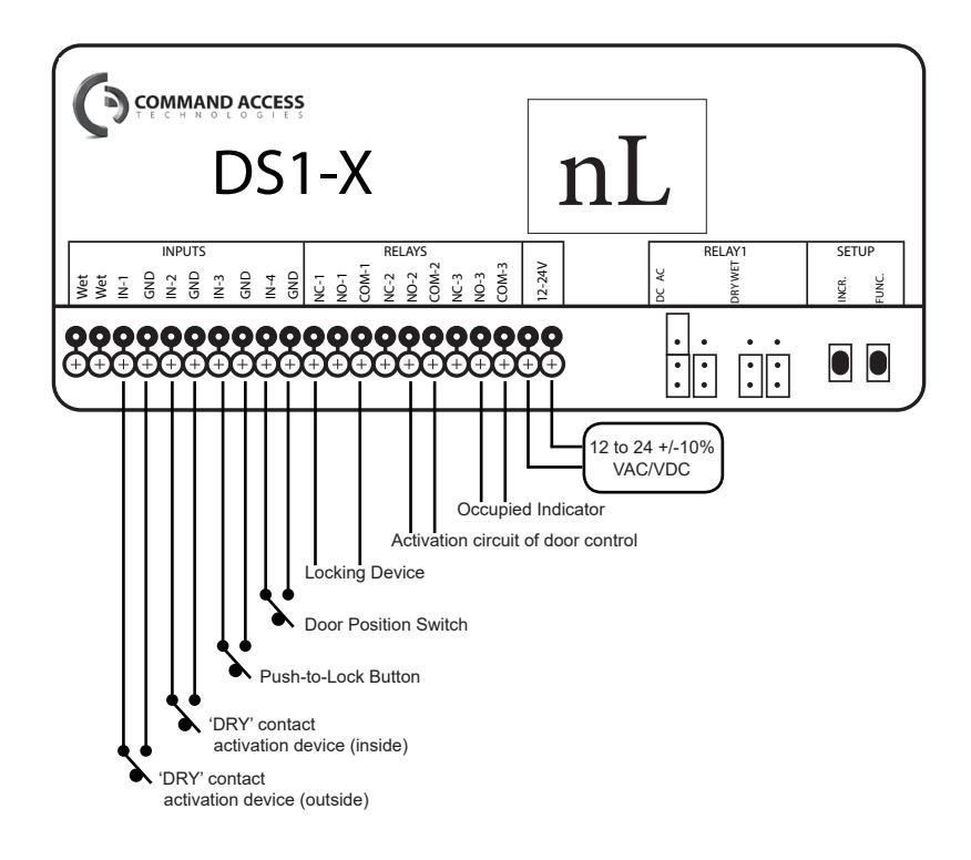
AVAILABLE PARAMETERS:
- h1 relay 1 hold time
- h2 relay 2 hold time
- d1 delay between relays 1 & 2
- d2 delay between relays 2 & 1
1. Trigger INPUT 1.
- RELAY 1 will close and hold for time h1.
- RELAY 2 will close after time delay d1 and hold for time h2.
2. Trigger INPUT 2.
- RELAY 2 will close and hold for time h2.
- RELAY 1 will close after time delay d2 and hold for time h1.
3. Trigger INPUT 3.
• RELAY 1 will close and hold for time h1.
4. Trigger INPUT 4.
• RELAY 2 will close and hold for time h2.
AVAILABLE PARAMETERS:
- h1 relay 1 hold time
- h2 relay 2 hold time
- d1 delay between relays 1 & 2
h1 must be greater than d1
1. Trigger INPUT 1.
- RELAY 1 will close and hold for time h1.
- RELAY 2 will close after time delay d1 and hold for time h2.
2. Trigger INPUT 3.
• RELAY 3 will close and INPUT 1 will be inhibited.
3. Trigger INPUT 2.
- RELAY 1 will close and hold for time h1.
- RELAY 2 will close after time delay d1 and hold for time h2.
- RELAY 3 will open.
FUNCTION nL NOTE: INPUT 3 will not function unless INPUT 4 is closed. INPUT 4 should be closed when door is closed.

PROGRAMMING PARAMETERS (cont)
nU– normally unlocked restroom
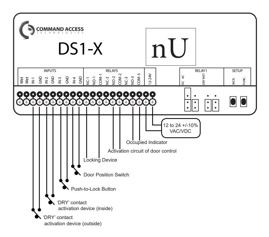
AVAILABLE PARAMETERS:
h2 - relay 2 hold time d1 - delay between relays 1 & 2
1. Trigger INPUT 1.
- RELAY 2 will close and hold for time h2.
-
2. Trigger INPUT 3.
- RELAY 1 and 3 will close and INPUT 1 will be inhibited.
-
3. Trigger INPUT 2.
- RELAY 1 will open.
- RELAY 2 will close after time delay d1 and hold for time h2.
- RELAY 3 will open.
FUNCTION nU NOTE: INPUT 3 will not function unless INPUT 4 is closed. INPUT 4 should be closed when door is closed.
dN– 3-relay sequence with 'day / night mode'
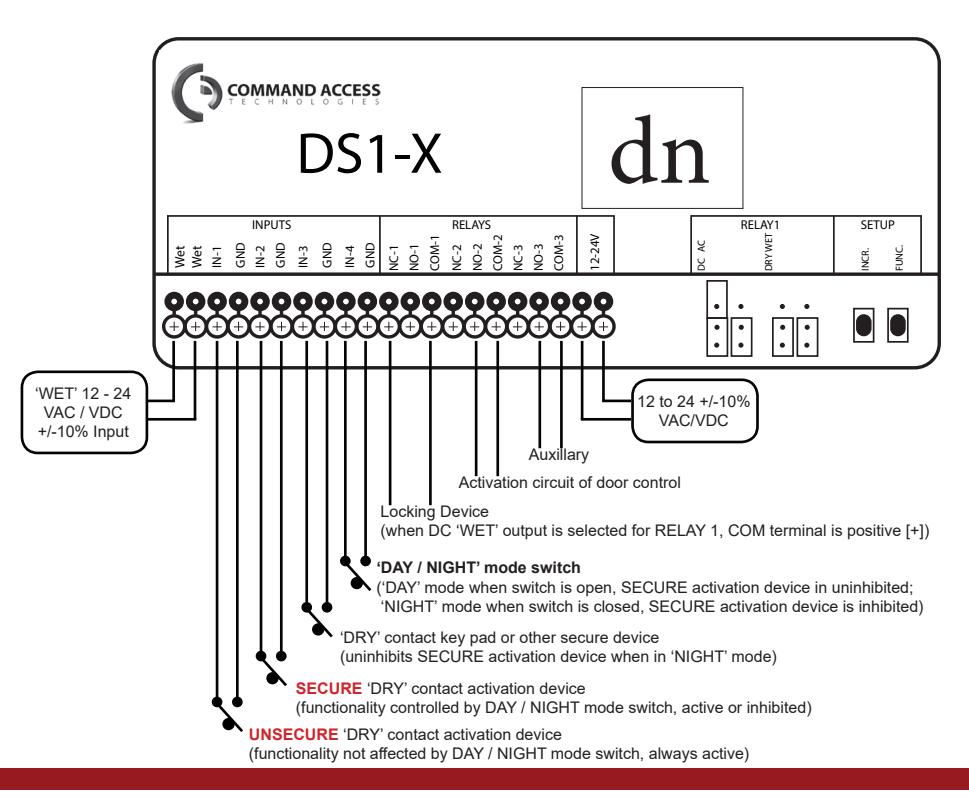
AVAILABLE PARAMETERS:
h1 - relay 1 hold time
h2 - relay 2 hold time
h3 - relay 3 hold time
d1 - delay between relays 1 & 2
d2 - delay between relays 1 & 3
1. Trigger INPUT 1, INPUT 2, or 'WET'.
- RELAY 1 will close and hold for time h1.
- RELAY 2 will close after time delay d1 and hold for time h2.
- RELAY 3 will close after time delay d2 and hold for time h3.
2. Trigger INPUT 3.
- RELAY 1 will close and hold for time h1.
- INPUT 2 will be uninhibited for 5 seconds.
FUNCTION dn NOTE: INPUT 2 will only function if INPUT 4 is open.

TEST
Upon completion of jumper settings, wiring, and programming, test the DS1-X to ensure all function parameters are working correctly and as intended for the specific application.
RELAY STATUS
| STATUS | DESCRIPTION |
|---|---|
| r1 | relay 1 closed when wired NO or open when wired NC |
| r2 | relay 2 closed when wired NO or open when wired NC |
| r3 | relay 3 closed when wired NO or open when wired NC |
| r- | relay 1 and relay 2 closed when wired NO or open when wired NC |
| r- | relay 1 and relay 3 closed when wired NO or open when wired NC |
| r- | relay 1, relay 2, and relay 3 closed when wired NO or open when wired NC |
FUNCTION CROSS REFERENCE
| DS1 FUNCTION | DS1-X FUNCTION |
|---|---|
| 21 | 22 |
| 25 | 28, 29 , 36 , or 37 |
| 35 | 36 or 37 |
| 75 | 28, 29 , 36 , or 37 |
TROUBLESHOOTING
|
DS1-X will not react
to any inputs |
Incorrect power |
Verify power supply of 12 to 24
VAC/VDC +/-10% is wired to correct terminals |
|---|---|---|
| Not programmed |
Ensure a function is programmed,
DS1-X does not show 00, and all ' h' values are set to at least 01 |
|
| Incorrect wiring |
Verify wiring is applied exactly as
described for specific function programmed |
|
| Defective DS1-X | Replace DS1-X | |
| DS1-X has no output | Incorrect output devices |
Ensure proper devices are
connected to outputs for the specific function programmed |
| Not programmed |
Ensure a function is programmed,
DS1-X does not show 00, and all ' h' values are set to at least 01 |
|
| Incorrect wiring |
Verify wiring is applied exactly as
described for specific function programmed |
|
| Incorrect jumper settings |
Ensure all jumpers are configured
correctly for specific application |
|
| Defective DS1-X | Replace DS1-X | |
|
DS1-X output is con
stant/maintained |
One or more of IN-1
through IN-4 have shorted |
Resolve respective short |
| E1, E2, E3, E4, E5 | EEPROM error | Reset DS1-X and reprogram |