DS1+ Installation Instruction
Open the original PDF document
View PDFd s 1 +

| Input Voltage: | 12/24VAC/VDC | Contact Rating: | 3A @ 30VDC | |
|---|---|---|---|---|
| Current Draw: |
20mA Idle / 60mA Operating
Response Time: |
0.3 seconds | ||
| Inputs: |
2 Wet and 2 Dry N.O.
Outputs: |
2 x Form C (SPDT) | ||
| Electrical Life: | 100,000 @ rated capacity | Modes: | 8 | |
| Time Delay |
D.O.R. #1: 1-30 Seconds
D.O.O. #2: 1-30 Seconds D.O.R. #3: 1-30 Seconds |
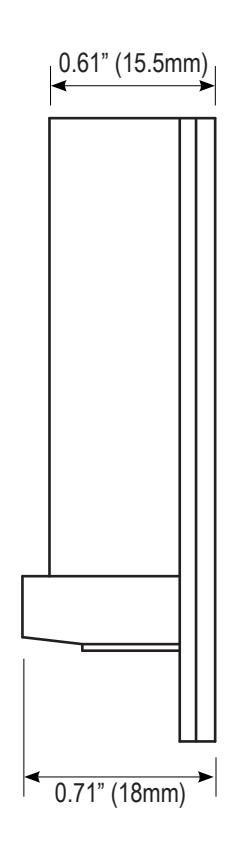
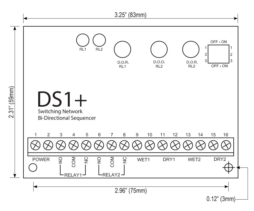
Dimensions: |
Width- 3.25" (83mm)
Height- 2.96" (59mm) Depth- 0.71" (18mm) |
|
| SW1 | SW2 | SW3 | Mode | Description |
|---|---|---|---|---|
| OFF | OFF | ON | 1a and 1b | Momentary and Momentary Apartment |
| ON | OFF | ON | 2 | Access Control (Maintained) |
| ON | ON | ON | 3 | Smoke Evacuation |
| OFF | ON | ON | 4 | Latching / Ratchet Mode |
| OFF | OFF | OFF | 5 | Bi-Directional Sequencer - Momentary |
| ON | OFF | OFF | 6 | Bi-Directional Sequencer - Maintained |
| OFF | ON | OFF | 7 | Restroom Control - Normally Unlocked |
| ON | ON | OFF | 8 | Restroom Control - Normally Locked |

Momentary Operation
In the Momentary position, even a stuck switch input will allow the door to time out and close, thereby providing security to occupants. The DS1+ will however still operate normally if one of the other inputs is activated. Essentially, it ignores the faulty activation source as all inputs are isolated.
Additionally, we provide a direct connection from an apartment interphone panel. Only Relay 1 (strike) will operate when a voltage is applied to this input. A vestibule courtesy switch will be energized for the set by Pot. 1.
Maintained Operation
Select Relay 1 Maintained for an access control application. When a maintained signal is applied to WET 1 input, the lock will remain energized, while the DRY 2 input allows a wall switch to open the door.
An input of DRY 1 will always unlock and open the door.
Select Relay 2 maintained if you are connecting the DS1+ to a fire alarm panel or to a pressure sensor.
In this mode the lock will fire momentarily but the operator relay will be held in as long as the input is maintained.
Latching/Ratchet Operation
In this mode the DS1+ will latch Relay 2 with a momentary activation of Dry/Wet 1. Relay is released when Dry/Wet 1 are activated a second time. If Dry/Wet 2 are activated, Relay 1 and Relay 2 are latched until Dry/Wet2 are activated again.
Washroom Door Controller
In this mode, complete control of a single occupant barrier-free washroom is obtained. It allows the user to lock and secure the door from the inside by depressing a Push-to-Lock button. The exterior wall switch is removed electronically from the circuit. To exit the washroom, simply exit manually via the lever-handle set (the door contact switch resets the relay, or, press the interior wall switch to unlock and activate the door operator. The door remains unlocked upon closure.
Another feature is the ability to use the DS1+ on "Normally Secure" washrooms. In this mode, the door is usually locked. To gain access, the user must first swipe a card, or enter a code into the Access System (i.e. keypad), which then signals the DS1+ to unlock and open the door. Once inside, the occupant presses the Push-to-Lock button, which removes the exterior wall switch from the circuit.
Exiting may be accomplished manually via the lever-handle set (the door contact switch resets the relay), or, by pressing the interior switch to unlock and activate the door operator. The door will re-lock upon closure.
Bi-Directional Door Sequencer
In this mode, the relay will sequence two automatic doors, in both directions. Upon a switch closure from one side, a signal is sent to the first door (Relay 1) then after an adjustable delay, the second door (Relay 2) receives a signal. When a switch closure is made from the opposite side, the sequence is reversed – Relay 2 is activated, then after the adjustable delay, relay 1 activates.
When used as a door sequencer the user can select either momentary position for the inputs or maintained position. In the momentary position, even a stuck switch input will allow the door to time out and close, thereby providing security to occupants.
The DS1+ will however still operate normally if one of the other inputs is activated. Essentially, it ignores the faulty activation source, as all inputs are isolated. In the maintained position, a switch that is held on will cause its respective relay (operator) to be held on. So, switch #1 would hold in relay #1 and switch #2 would hold in relay #2.
If an emergency (or anti-entrapment) switch is desired in the vestibule, then wire that switch directly to one of the operator inputs. Usually the exterior door is used in this case.
IMPORTANT: Do not apply power until you have read the instructions fully and made the required adjustments.

INSTALLATION
Mounting
The LEDs are visible through the wrap-around sleeve, which also has cutouts for adjusting the potentiometers and setting the dip switch. Once the unit has been adjusted it may be tucked up into the operator header or affixed using the supplied Velcro.
Wiring
Wiring of this unit is dependent on the mode desired; however, the following commonalities apply.
Note: Do not wire Safety Devices to the DS1+. If installed, wire your safety device directly to the operator control box as per usual.
IMPORTANT: Do not apply power to the unit until all secondary wiring is complete and dip switches have been set.
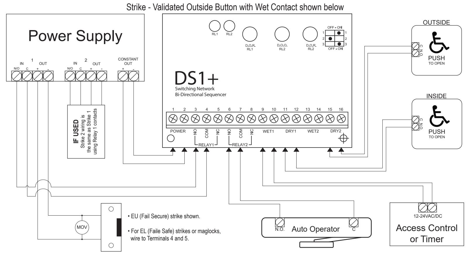
Both relay outputs are Form C and rated at 3amps maximum. Use Relay 1 for the strike or electromagnet. Generally, the N.O. and COM terminals (3 and 4) are used for a strike and COM and N.C. (4 and 5) are used with an electromagnet. The door operator will be wired to Relay 2 N.O. and COM terminals (6 and 7). In a door sequencing application, door 1 is Relay 1 and door 2 is Relay 2. The unit will operate on 12 or 24 volts, AC or DC. Connect to Terminals 1 and 2 which are non-polarity sensitive.
APPLICATIONS AND SET-UP INSTRUCTIONS
Standard Timer Mode (Mode 1)
Set dip switches as shown.
Connect a dry contact such as a wall switch to DRY1 (Terminals 11 and 12). A wet (powered) output connects to WET 2 (Terminals 13 and 14). Upon a switch activation the strike relay will fire for the time set by potentiometer 1 ( DOR RL1 ). After a delay, adjustable by potentiometer 2 ( DOO RL2 ), the operator will fire. The hold time for Relay 2 is set with potentiometer 2 ( DOR RL2 )
Most modern door operators have built-in time delays, and if so, it is usually desirable to use them to add sufficient hold open time. In this case adjust the DS1+ to send just a momentary pulse (1 or 2 seconds only). Observe the door and adjust timers until desired operation is observed.
The above dip switch setting is also used for applications such as apartment entries with an interphone panel. In each case the interphone input WET 1 (Terminals 9 and 10) will activate the strike relay only. If a courtesy switch is located in the vestibule, it is connected to DRY 2 (Terminals 15 and 16).
This input is only active when the strike relay is energized. Another application using this mode is door sequencing in one direction only. Connect Door 1 operator to Relay 1 and Door 2 operator to Relay 2. The delay between the two doors is adjusted via the DOO RL2 potentiometer. For bi-directional sequencing refer to specific set-up instructions below.
Access Control Mode (Mode 2)
Set dip switches as shown.
Typically, the access panel (or time clock) will be wet (powered) therefore connect to WET 1 (Terminals 9 and 10).
The exterior activating switch is wired to DRY 2 (Terminals 15 and 16). This input signals the door operator (Relay 2) and is only active when the strike relay is energized.

An interior switch may be connected to Dry 1 (Terminals 11 and 12). This input will always unlock and open the door when activated (regardless of the status of input connected to WET 1). If interior switch is wet (powered) connect to WET 2 (Terminals 13 and 14).
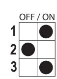
Smoke Evacuation Mode (Mode 3)
Set dip switches as shown.
| OFF / ON | |||
|---|---|---|---|
| 1 | |||
| 2 | |||
| 3 | |||
Suitable for connection to a Fire Alarm Panel, this mode will fire the electric lock momentarily, then hold in the operator relay until the input is released.
Connect the wet (powered) output of the Fire Panel to WET 2 (Terminals 13 and 14). A device with a dry output such as a presence sensor will connect to DRY 1 (Terminals 11 and 12)
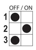
Latching/Rachet Mode (Mode 4)
Set dip switches as shown.
| OFF / ON | |||
|---|---|---|---|
| 1 | |||
| 2 | |||
| 3 | |||
Latching – Upon receipt of a signal (or contact closure) on WET 1 or DRY 1, Relay 1 will activate for an adjustable time. Then after an adjustable time, Relay 2 will activate. Relay 2 will stay held until a second contact closure on DRY/WET 1.
Rachet – Upon receipt of a signal (or contact closure) on Wet 2 or Dry 2, Relay 1 will activate and stay latched. Then after an adjustable time, Relay 2 will activate and stay latched. A second activation of Wet/Dry 2 will release both relays.
Bi-Directional Sequencing Mode
Mode 5: Momentary Mode 6: Maintained
Set dip switches as shown.
| MOM | MAIN | |||||
|---|---|---|---|---|---|---|
| OFF / ON | OFF / ON | |||||
| 1 | 1 | |||||
| 2 | 2 | |||||
| 3 | 3 | |||||
Turn on power and activate the interior input (switch). Observe LED 1 , which should light immediately. The length of hold time is determined by adjusting the pot marked DOR/RL1 clockwise for more time, counterclockwise for less time. The delay between the two doors is adjusted via the DOO RL2 potentiometer. After the above-mentioned delay, LED 2 should light. The length of hold time is adjusted by the pot marked DOR/RL2.
The ideal time delay between the two doors is best set by actual walk-testing. It should be set so that a person can walk in either direction without having to pause before the second door activates. Test in both directions.
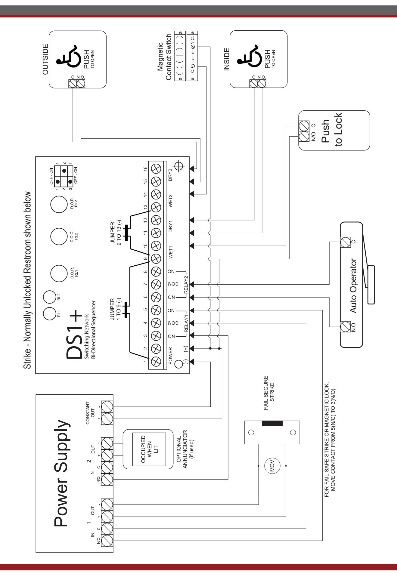
Washroom Door Controller
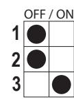
For Normally Unlocked Door set dip switches as shown.
OFF / ON 1 2 3
For Normally Locked Door set dip switches as shown.
Connect the inputs from the various switches according to the appropriate diagram. Please note that the magnetic contact switch should be Normally Closed switch (contacts closed when door is closed, and contacts open when the door opens).

The Push to Lock switch should be a Normally Open momentary switch. The door lock is connected to Relay 1 (Terminals 3 and 4, or, 4 and 5). Both fail safe and fail secure locks may be used.
The automatic door operator is typically connected to Relay 2 (N.O. Terminals 6 and 7). The unit will operate on 12 or 24 volts, Ac or DC. Connect to Terminals 1 and 2 (they are non-polarity sensitive).
Set Up
Apply power to the DS1+ and observe the LEDs. Pot DOR/RL1 adjusts the lock release time (up to 30 seconds). The pot marked DOO/RL2 adjusts the delay before the door operator relay fires and the operator hold time is adjusted with pot DOR/RL2.
Normally Unlocked Mode (Mode 7)
Press the exterior wall switch. If the washroom is unoccupied the door will open automatically. After entering the washroom, wait for the door to close, then push to Lock button.
The DS1+ will energize the lock and remove the outside wall switch from the circuit.
To exit the washroom, two options are available:
- To have the door unlock and open automatically, push the interior wall switch. This also resets the relay for the next person to use.
- Manual use. The door may also be used manually. To exit the washroom, turn the lever handle and pull(push) the door open. The magnet switch resets the relay for the next person to use.
Normally Locked Mode (Mode 8)
In this situation the door is always locked from the exterior.
Enter code or swipe card. The door unlocks and after the adjustable delay, opens the door. After entering the washroom, wait for the door to close, then push the Lock button. The door is now locked and the outside access control device is removed from the circuit.
To exit the washroom, two options are available:
- To have the door unlock and open automatically, push the interior wall switch. This also resets the relay for the next person to use.
- Manual use. The door may also be used manually. To exit the washroom, turn the lever handle and pull(push) the door open. The magnet switch resets the relay for the next person to use.
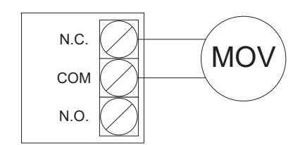
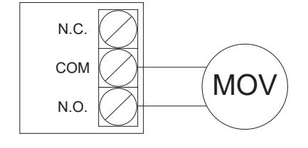
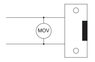
NOTICE:
Large inductive loads may cause damage to the relay contacts. In these cases, a 47V rated varistor (MOV) must be used (included).
System Inspection Instructions
After the installation and operational check of the system:
- Place warning label on the door (as per ANSI A156.10 or A156.19 guidelines). This will advise the person entering the swing side zone that the door will remove.
- Instruct the owner on door system operation and how to test it. This should be checked on a daily basis.
- Instruct the owner on what to do if the door or any of its components become damaged.
- Strongly recommend to the owner that the complete entry be inspected twice a year as part of the service agreement.
WIRING DIAGRAMS

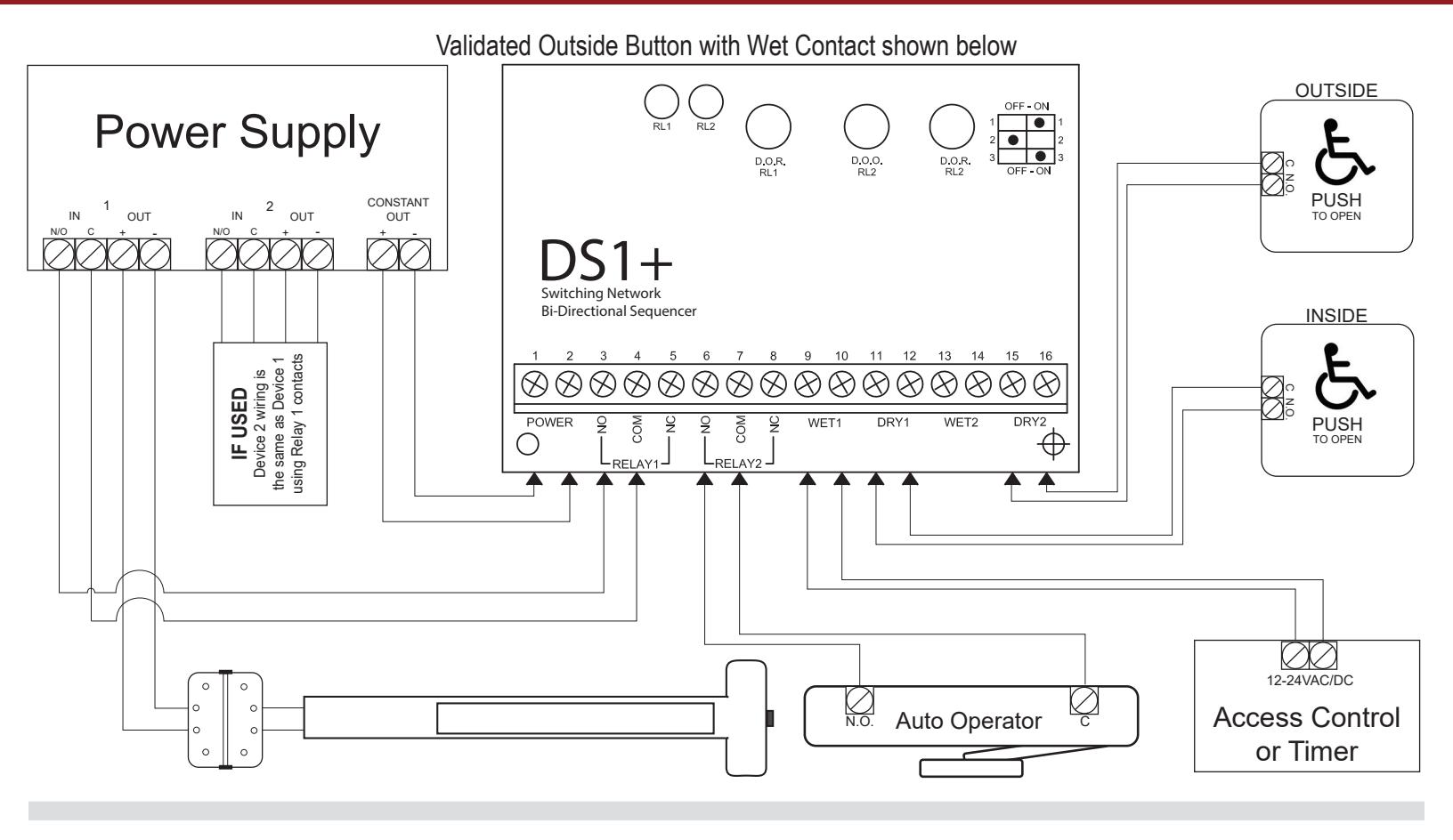
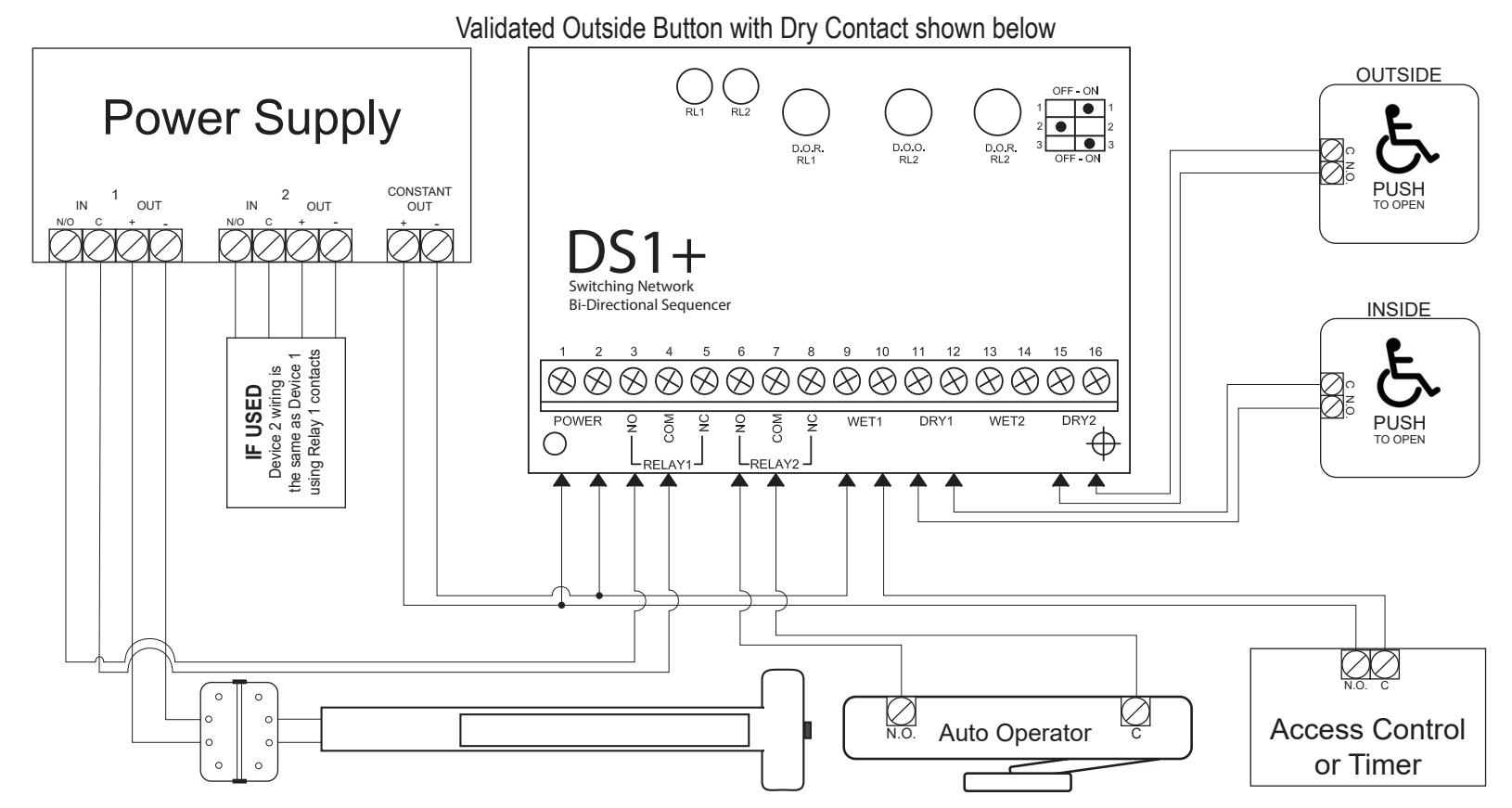
WIRING DIAGRAMS

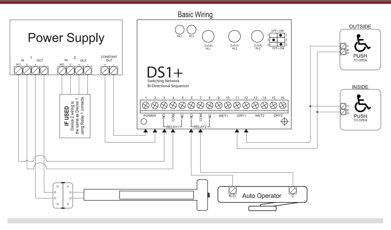
WIRING DIAGRAM