DS1 Installation Instruction
Open the original PDF document
View PDFInstallation Instructions DS1 Delay/Sequencer Board

STEP 1 - Preparation
IMPORTANT : Do not apply power to the unit until you have read the instructions fully and made the required adjustments.
STEP 2 - Installation
Mounting
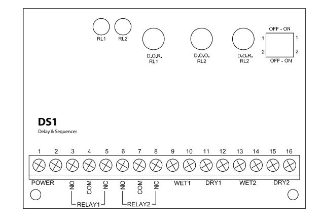
The LED's are visible through the wrap-around sleeve, which also has cutouts for adjusting the potentiometers, and setting the dip-switch. Once the unit has been adjusted, it may be tucked up into the operator header or affixed using the supplied Velcro.
Wiring
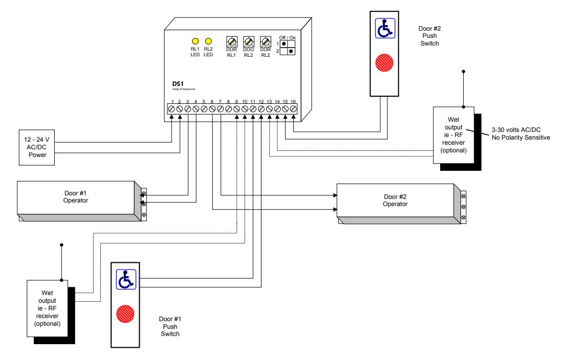
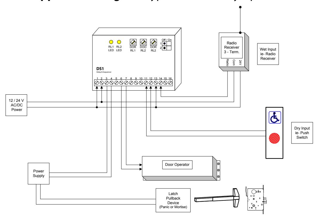
Wiring of this unit is dependent on the mode desired, however the following commonalities apply. Note: Do not wire Safety devices to the DS1. If installed, wire your safety device directly to the operator control box as per usual.
CAUTION : Do not apply power to the unit until all secondary wiring is complete, and dip-switches have been set.
Both relay outputs are Form C and are rated at 3 amps maximum. Use relay # 1 for the strike or electromagnet. Generally the N.O. & COM. terminals (#3 & 4) are used for a strike, and COM & N.C. (#4 & 5) are used with an electromagnet.
The door operator will be wired to relay #2 N.O. & COM terminals (#6 & 7). In a door sequencing application, door 1 is relay #1, and door 2 is relay #2.
The unit will operate on 12 or 24 volts, AC or DC. Connect to Terminals 1 & 2, which are non-polarity sensitive.
DS1 Electrical and Mechanical
| 1 | Power Input | 12/24 Volts AC/DC |
| 2 | Power Input | Non-polarized |
| 3 | Relay1 - NO | |
| 4 | Relay1 - COM | FORM C |
| 5 | Relay1 - NC | |
| 6 | Relay2 - NO | |
| 7 | Relay2 - COM | FORM C |
| 8 | Relay2 - NC | |
| 9 | Wet1 Input | Powered Input 1 |
| 10 | Wet1 Input | · |
| 11 | Dry1 Input | Non-Powered Input 1 |
| 12 | Dry1 Input | • |
| 13 | Wet2 Input | Powered Input 2 |
| 14 | Wet2 Input | · |
| 15 | Dry2 Input | Non-Powered Input 2 |
| 16 | Dry2 Input | · |
COMMAND ACCESS TECHNOCIOSIO
Installation Instructions - DS1 Delay/Sequencer Board
STEP 3 - Applications & Set-up Instructions
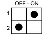
STANDARD TIMER MODE
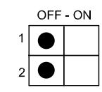
Set dipswitches as shown > Refer also to Diagram 01.
Connect a dry contact such as a wall switch to DRY1 (Terminals 11 & 12). A Wet (powered) output connects to WET 2 (Terminals 13 & 14).
Upon a switch activation the strike relay will fire for the time set by potentiometer 1 ( DOR RL1 ). After a delay, adjustable by potentiometer 2 ( DOO RL2 ), the operator relay will fire. The hold time for relay #2 is set with potentiometer 2 ( DOR RL2 ).
Most modern door operators have built-in time delays, and if so, it is usually desirable to use them to add sufficient hold-open time. In this case adjust the DS1 to send just a momentary pulse (1 or 2 seconds only).
Observe the door and adjust timers until desired operation is observed.
The above dipswitch setting is also used for applications such as apartment entries with an interphone panel. Refer to Diagrams 03a & 03b.
In each case the interphone input ( WET 1 ) will activate the strike relay only. If a courtesy switch is located in the vestibule, it is connected to DRY 2 (Terminals 15 & 16). This input is only active when the strike relay is energized.
Another application using this mode is door sequencing in one direction only. Connect Door 1 operator to relay 1, and door 2 operator to relay 2. The delay between the two doors is adjusted via the DOO RL2 potentiometer. For bi-directional sequencing refer to specific set-up instructions below.
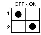
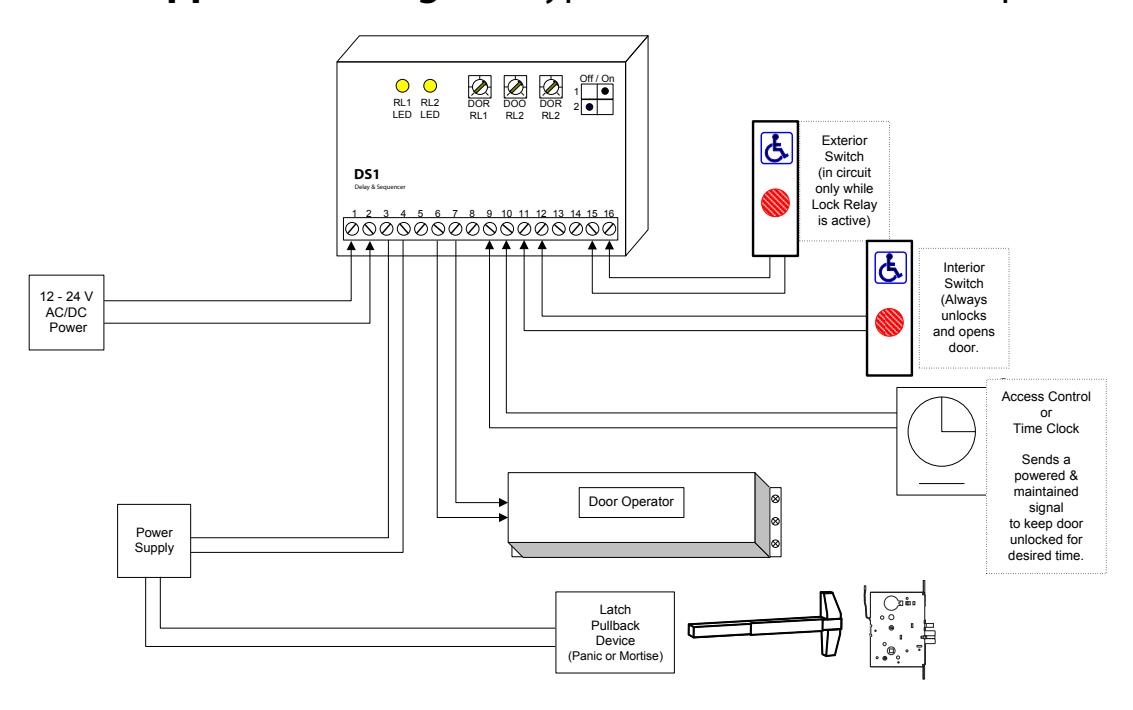
EXTENDED TRIGGER MODE - RELAY 1
Set dipswitches as shown > Refer also to Diagram 02b.
Typically the access panel (or time clock) will be wet (powered) therefore connect to WET 1 (Terminals 9 &10).
The exterior activating switch is wired to DRY 2 (Terminals 15 & 16). This input signals the door operator (Relay 2), and is only active when the strike relay is energized.
An interior switch may be connected to DRY 1 (Terminals 11 & 12). This input will always unlock and open the door when activated. (Regardless of the status of input connected to WET 1 ).
If the interior switch is Wet (powered) connect to WET 2 (Terminals 13 & 14).
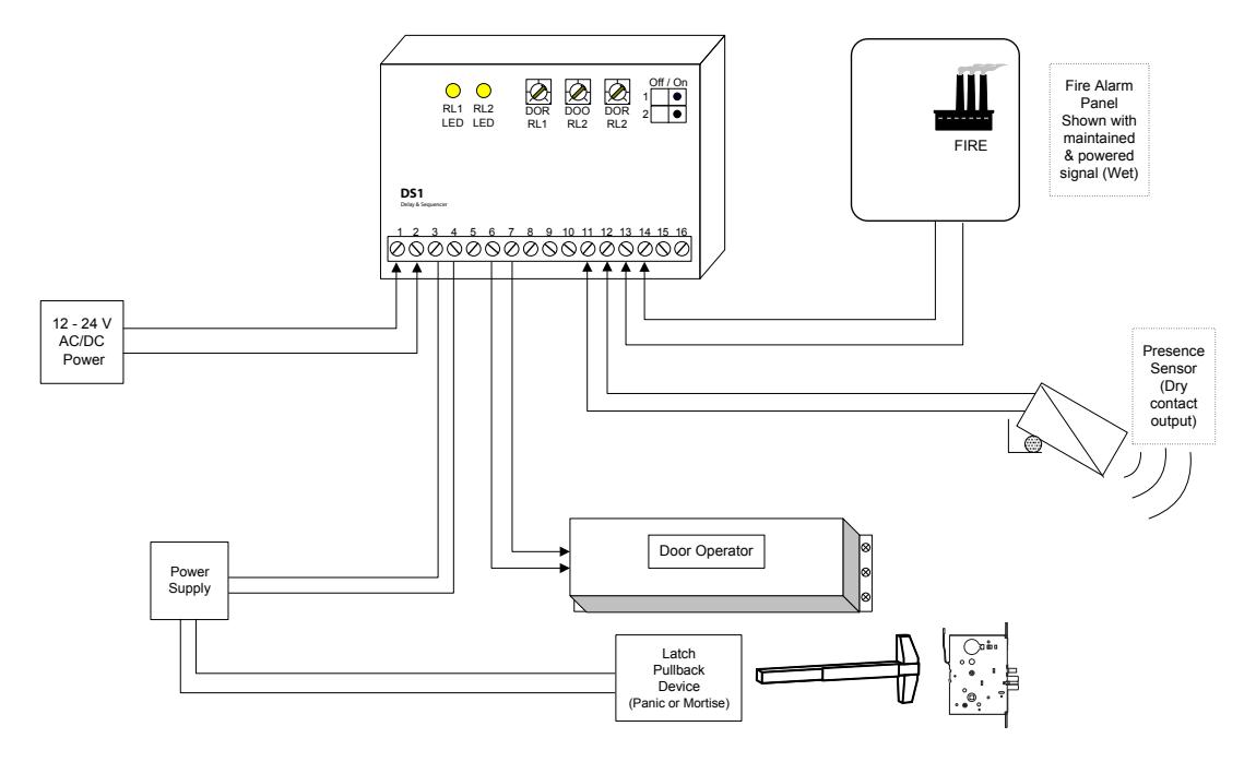
EXTENDED TRIGGER MODE - RELAY 2
Set dipswitches as shown > Refer to Diagram 02a.
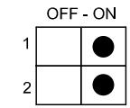
Suitable for connection to a Fire Alarm Panel, this mode will fire the electric lock momentarily, then hold in the operator relay until the input is released. Connect the Wet (powered) output of the Fire panel to WET 2 (Terminals 13 & 14)
A device with a dry output such as a Presence sensor will connect to DRY 1 (Terminals 13 & 14).
Bi-Directional Sequencing MODE
Set dipswitches as shown > Refer to Diagram 03.
Turn on power and activate the Interior input (switch). Observe LED1 , which should light immediately. The length of hold time is determined by adjusting the pot marked DOR/RL1 , clockwise for more time, counter clockwise for less time.
The delay between the two doors is adjusted via the DOO RL2 potentiometer.
After the above-mentioned delay, LED2 should light. The length of hold time is adjusted by the pot marked DOR/ RL2 .
The ideal time delay between the two doors is best set by actual walk-testing. It should be set so that a person can walk in either direction without having to pause before the second door activates. Test in both directions.
If an emergency (or anti-entrapment) switch is desired in the vestibule, then wire that switch directly to one of the operator inputs. Usually the exterior door is used in this case.
Once the desired operation is achieved, proceed to Section 4, for System Inspection Instructions .

Installation Instructions - DS1 Delay/Sequencer Board
STEP 4 - System Inspection Instructions
After the Installation and operational check of the system:
- 1. Place warning label on the door (as per ANSI A156.10 or A156.19 guidelines). This will advise the person entering the swing side zone that the door will move.
- 2. Instruct the owner on door system operation and how to test it. This should be checked on a daily basis.
- 3. Instruct the owner on what to do if the door or any of its components become damaged.
- 4. Strongly recommend to the owner that the complete entry be inspected twice a year as part of the service agreement.
STEP 5 - Technical Data
Model DS1
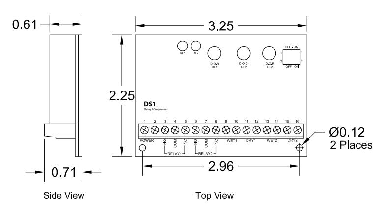
Size 3 ¼" x 2 ¼" x ¾"
Mounting Velcro or double-sided tape Enclosure Protective paper sleeve. Operating voltage 12 / 24 Volts, AC / DC
Current Draw 18 mA standby, 40 mA max.
Response time 0.3 seconds
Inputs 2 x "dry" contacts,
2 x "wet" contacts:
(3-30 V AC/DC, Optically isolated, non-polarity sensitive).
Relay Output 2 x Form C (SPDT) Relay contact rating 3 amps @ 20 VDC
Time Delays DOR #1 1 to 30 seconds
DOO #2 1 to 30 seconds DOR #2 1 to 30 seconds
Electrical Life 100,000 operations @ rated capacity
500,000 operations @ ½ rated capacity

DS1 Application Diagram (typical Momentary Operation) dia. 1
DS1 Application Diagram (with Maintained Operator Output) dia. 2a

dia. 2b DS1 Application Diagram (typical Maintained Lock Output)
dia. 3 DS1 Application Diagram (Bi-Directional Sequencer Operation)