DL20 Installation Instruction
Open the original PDF document
View PDF

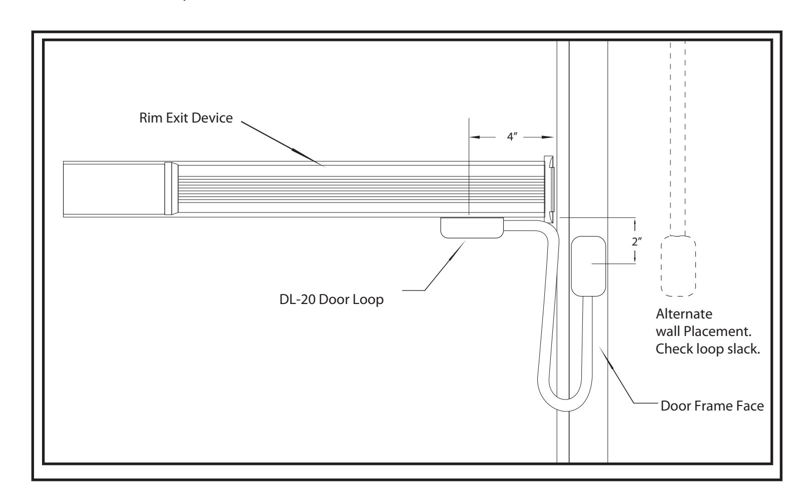
Mounting Instructions For "DL20" Door Loops
THIS DIAGRAM APPLIES TO
all DL Series Door Loops
- 1- Locate the centerline of the door loop on the underside of the Exit Device Housing 4" from sot of frame and 1" from face of door
- 2- Locate the centerline of the door loop for the face of frame 2" down from the edge of the Exit Device
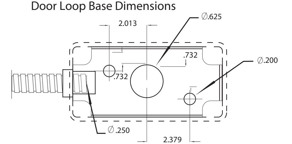
- 3- Drill pilot holes (#24 drill) to mount the base and a 5/8" hole for wire conduit.
- 4- Mount base using #10 SMS.
- 5- Thread electrical wires through door loop.
- 6- Install covers with #8 SMS screws
Door Loop exible conduit can be eld cut NOTES: Maximum electrical wires: 7 ea. 18 awg, 10 ea. 22 awg