Corbin Russwin PED5000 Series PED5400(A)(HC)(HC4) Wide Stile SVR Installation Instructions_FM583
Open the original PDF document
View PDFInstallation Instructions

PED5400 Series (Standard, A, HC, & HC4)
Surface Vertical Rod Exit Devices

This product can expose you to lead which is known to the state of California to cause cancer and birth defects or other reproductive harm. For more information go to www. P65warnings.ca.gov.
1-800-543-3658 • techsupport.corbinrusswin@assaabloy.com
WARNING
Attention Installer: Improper installation may result in damage to the product and void the factory warranty.
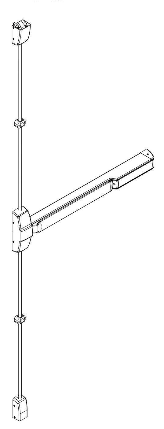
Surface Vertical Rod Exit Device
Installation Instructions
Screw Chart

| WHERE USED |
|---|
| (4) CHASSIS CORNER MOUNTING HOLES (METAL DOOR) (3) TOP CASE (STD.) (METAL DOOR) , HC (3) BOTTOM CASE (STD.) |
| (METAL DOOR) (4) CHASSIS CORNER MOUNTING HOLES (WOOD DOOR) (3) TOP CASE (STD.) (WOOD DOOR) (2) TOP CASE (FIRE RATED) BOTTOM MOUNTING HOLES (WOOD DOOR) (3) BOTTOM CASE (STD.) (WOOD DOOR) (2) BOTTOM CASE (FIRE RATED) TOP MOUNTING HOLES (WOOD DOOR) |
|
(2) REAR MOUNTING PLATE
(METAL DOOR) |
| (2) REAR MOUNTING PLATE (WOOD DOOR) |
| (2) TOP CASE (HC) TOP MOUNTING HOLES (2) BOTTOM CASE (HC) BOTTOM MOUNTING HOLES |
| (2) TOP CASE (HC) BOTTOM MOUNTING HOLES (2) BOTTOM CASE (HC) TOP MOUNTING HOLES (4) 654 TOP LATCH STRIKE |
| (2) TOP CASE (FIRE RATED) BOTTOM MOUNTING HOLES (METAL DOOR) (2) BOTTOM CASE (FIRE RATED) TOP MOUNTING HOLES (METAL DOOR) (2) 648 TRANSOM STRIKE |
| (2) TOP CASE (FIRE RATED) TOP MOUNTING HOLES |
|
(2) BOTTOM CASE (FIRE RATED)
BOTTOM MOUNTING HOLES |
| _ |
Surface Vertical Rod Exit Device
Installation Instructions
Screw Chart

| DESCRIPTION |
TOTAL QTY
SUPPLIED |
WHERE USED |
|---|---|---|
|
#12-24 X 1" FLAT HEAD
MACHINE SCREW |
2 |
(2) 646 TOP STRIKE
(METAL FRAME) |
|
#12 X 1-1/2" FLAT HEAD
WOOD SCREW |
2 |
(2) 646 TOP STRIKE
(WOOD FRAME) |
|
#10 X 1-1/4" OVAL HEAD
WOOD SCREW |
2 |
(2) 648 TRANSOM STRIKE
(WOOD FRAME) |
|
#10-24 X 3/4" FLAT HEAD
MACHINE SCREW WITH CAULKING ANCHOR |
2 | (2) 624 BOTTOM STRIKE |
|
#12 X 1" FLAT HEAD
WOOD SCREW |
2 |
(2) 624 BOTTOM STRIKE
(WOOD FRAME) |
|
1/4"-20 X 2" FLAT HEAD
MACHINE SCREW W/ANCHOR |
2 (3) |
(3) 653 BOTTOM STRIKE
(2) 655 BOTTOM STRIKE |
|
#10-24 X 1-1/2" OVAL HEAD
MACHINE SCREW |
4 |
(2) TOP ROD GUIDE
(METAL DOOR) (2) BOTTOM ROD GUIDE (METAL DOOR) |
|
#10 X 1-3/4" OVAL HEAD
WOOD SCREW |
4 |
(2) TOP ROD GUIDE
(WOOD DOOR) (2) BOTTOM ROD GUIDE (WOOD DOOR) |
|
#8-32 X 5/16" W/ #6 OVAL HEAD
MACHINE SCREW |
12 |
(2) CHASSIS COVER
FRAME SIDE (2) END CAP (4) TOP CASE COVER (4) BOTTOM CASE COVER |
|
#8-32 X 5/8" W/ #6 OVAL HEAD
MACHINE SCREW |
2 |
(2) CHASSIS COVER
RAIL SIDE |
|
1/4"-20 X 2-3/8" KNURLED FLAT HEAD
MACHINE SCREW |
2 |
(2) EXIT TRIM
(IF USED) |
Surface Vertical Rod Exit Device
Installation Instructions

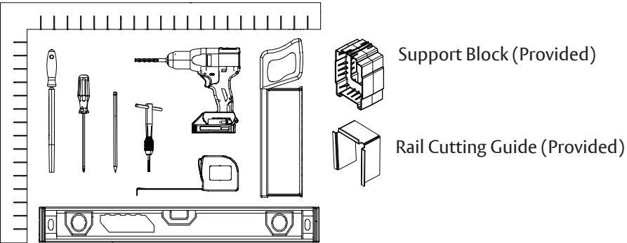
Tools Needed
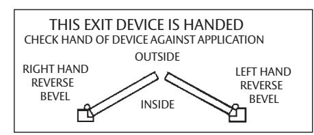
Handing
All PED5400 series exit devices are handed, except the PED5401, which is fi eld reversible. The PED5401 is shipped as LHR unless ordered as RHR.
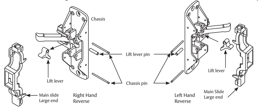
To Change Hand of PED5401 Exit Device:
- 1. Remove both chassis pins and main slide.
- 2. Remove lift lever pin and lift lever.
- 3. Rotate chassis 180° and reposition lift lever and lift lever pin as shown below
- 4. Position main slide with large end of main slide at the bottom and retain with chassis pins.

Before installation:
- 1. Install mullion, if used.
- 2. Fit and hang door.
- 3. Check the box's label for the size of the exit device.
- 4. For wood doors, use wood screws & prep accordingly.
Surface Vertical Rod Exit Device
Installation Instructions

Parts Description
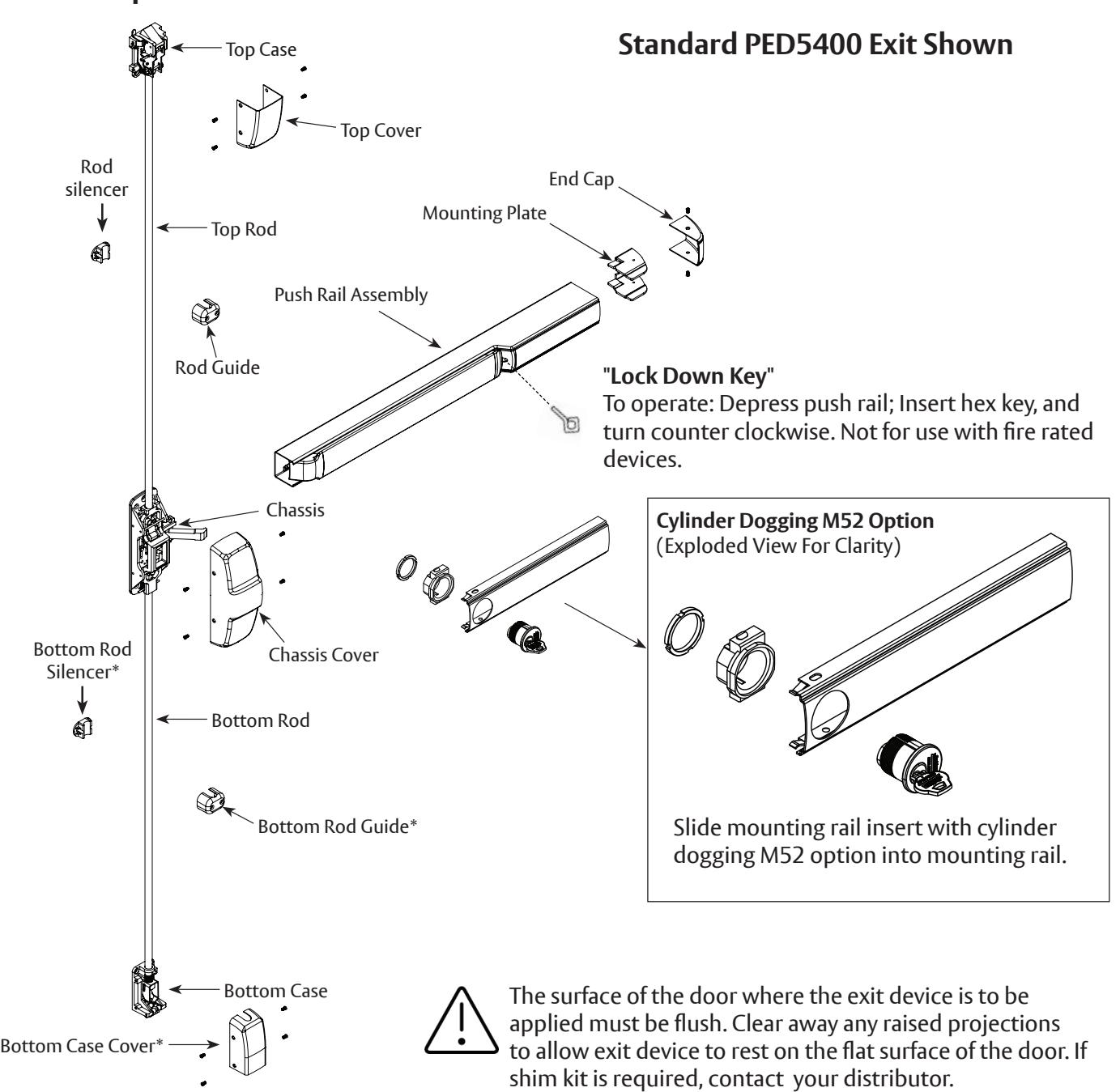
* Not included with M55 option.
Note: Please refer to trim and other installation instructions provided in the box.
Surface Vertical Rod Exit Device
Installation Instructions

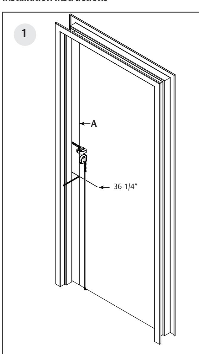
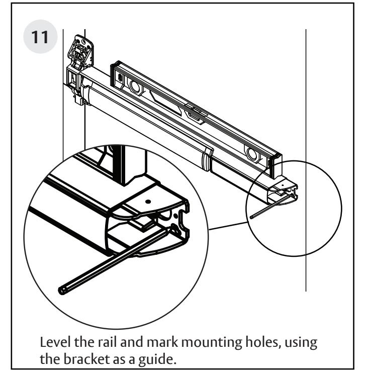
- With door closed, determine dimension "A" to located vertical reference line.
- If door stile is 4-1/2" wide or wider, "A" is 2-3/4". If door stile is less than 4-1/2", "A" is 1/2 the exposed width of the door stile when the door is closed against the door stop.
- Standard rail centerline height is 39-5/8" above the fi nished fl oor.
- Horizontal reference line is 36-1/4" standard. (Location of lower chassis mounting holes.)
Copyright © 2023, 2024, ASSA ABLOY Access and Egress Hardware Group, Inc. All rights reserved. Reproduction in whole or in part without the express written permission of ASSA ABLOY Access and Egress Hardware Group, Inc. is prohibited.
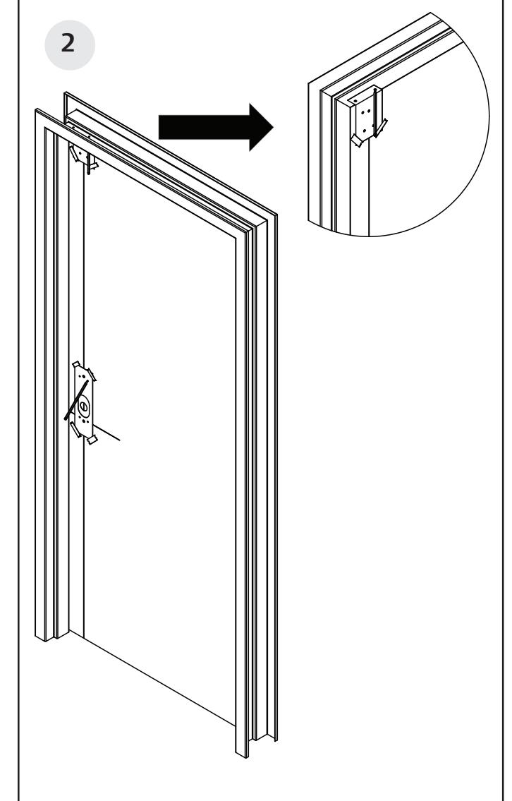
- With door closed, tape template for chassis/ trim on inside of door, along vertical and horizontal reference lines.
- Fold top case template and tape on inside of door along vertical reference lines.
Patent pending and/or patent www.assaabloydss.com/patents.
Surface Vertical Rod Exit Device
Installation Instructions

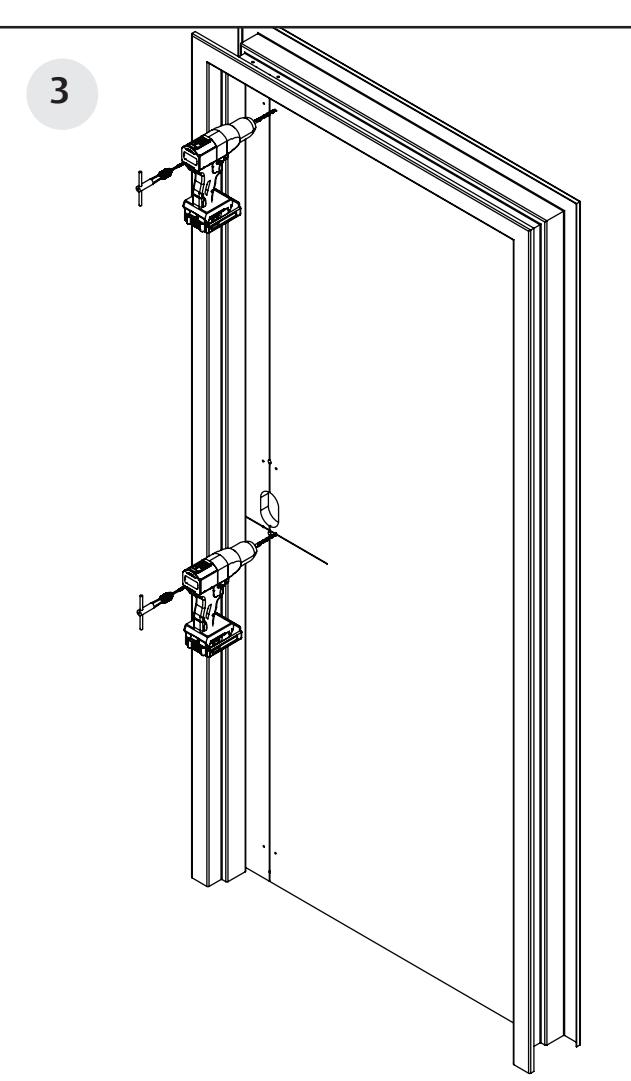
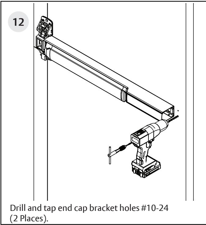
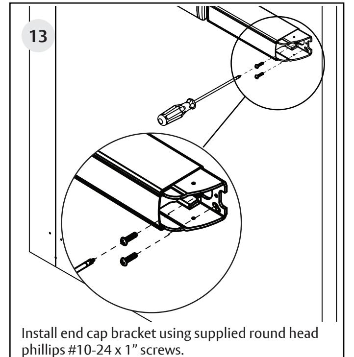
- Drill and tap all holes #10-24 from inside of door, for chassis and top case.
- Mortise pockets for outside trim, if required. See installation instructions supplied with trim for details.
NOTE: Any holes drilled from the outside need pilot holes drilled from the inside to ensure good alignment.
NOTE: For electrical trim applications, ensure access to a raceway from the trim to the electric hinge or armored door loop.
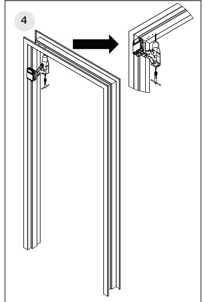
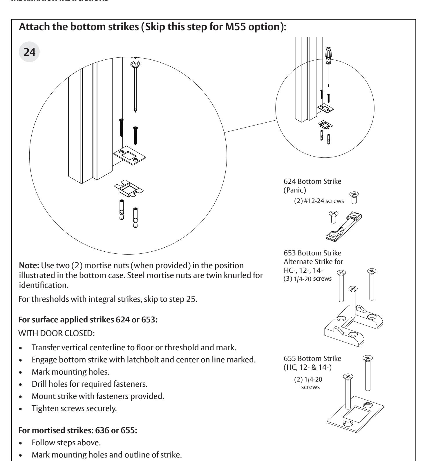
Drill and tap all strike mounting holes for #12-24 in locations for applicable strike.
Surface Vertical Rod Exit Device
Installation Instructions

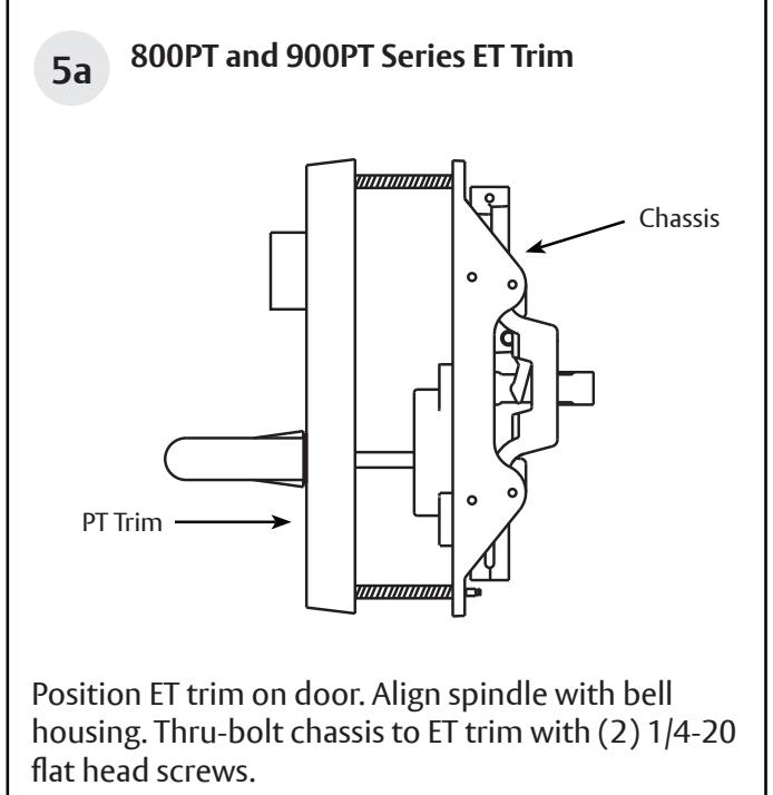
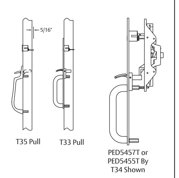
5b Thumb Piece Trim
Determining rim cylinder tail length.
For T33, T34, or T35 Trim:
- 1. Position trim on door (except T35).
- 2. Insert rim cylinder through trim plate (or cylinder collar for T35 trim).
- 3. Mark cylinder tail at 5/16" beyond inside door surface.
- 4. Remove cylinder and trim from door and cut tail piece as marked.
NOTE: Thumb Trim is not available for PED5400 HC Series Exit Devices.
Surface Vertical Rod Exit Device
Installation Instructions

5b Thumb Piece Trim, Continued
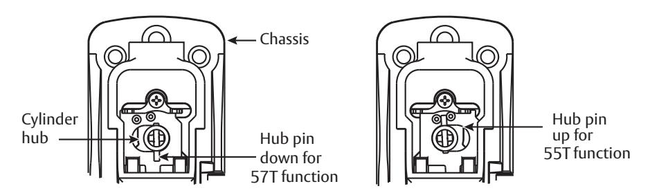
For PED5457T: Long end of pin faces down. Cylinder turns 180º in both directions.
For PED5455T: Long end of pin faces up. Cylinder turns 360º to the left or right.
Mounting Trim
- 1. Hold trim plate to door.
- 2. Insert cylinder and secure using supplied back plate.
- 3. Position cylinder hub within the chassis to correct position for desired function (see above).
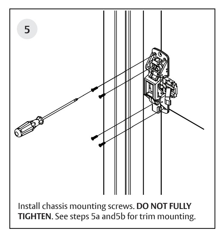
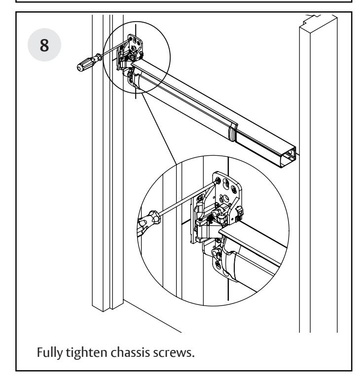
- 4. Position chassis on door, align cylinder tail with hub and secure chassis to door with (4) #10 fl at head screws using the corner mounting holes. DO NOT FULLY TIGHTEN.
NOTE: STS, FLL, FLW and MAL thru-bolt to chassis with (1) 1/4-20 fl at head screw. PTB trim thru-bolts to chassis with (2) 1/4-20 fl at head screws. DO NOT FULLY TIGHTEN.
Surface Vertical Rod Exit Device
Installation Instructions
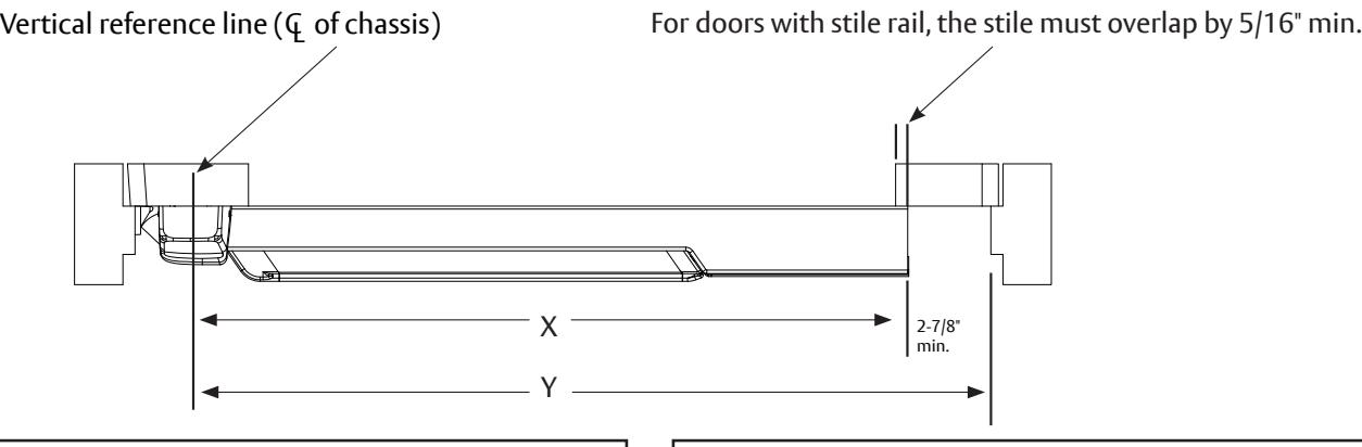
Rail cutting guide
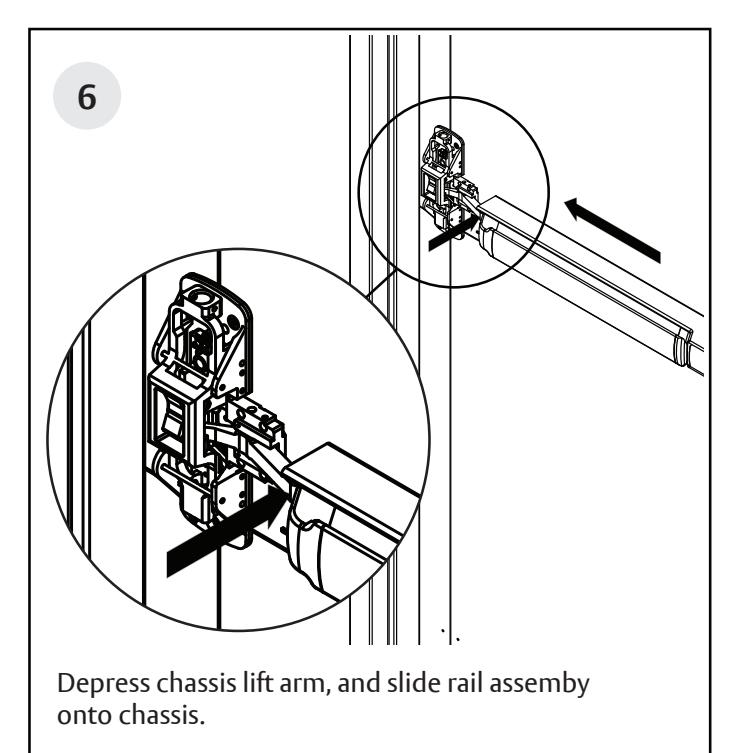
If the rail doesn't need to be cut, continue to page 12, step 6. If the rail must be cut, follow these steps on page 10 and 11:
Refer to the individual exit device installation instructions for rail cutting requirements / restrictions. Instructions will vary based on device type and options.
• Determine cut off dimension "X" by subtracting 2-7/8" from dimension "Y". Mark cut off point on mounting rail. (See below.)
| Information for Cutting Rails | |||
|---|---|---|---|
| Rail Sizes | Door Widths | ||
| Standard | Minimum | ||
| W032 | 32" | 24" | |
| W036 (Std.) | 36" | 33" | |
| W042 | 42" | 37" | |
| W048 | 48" | 43" | |
Do not cut closer than 1-5/8" from the the front edge of the rail insert.
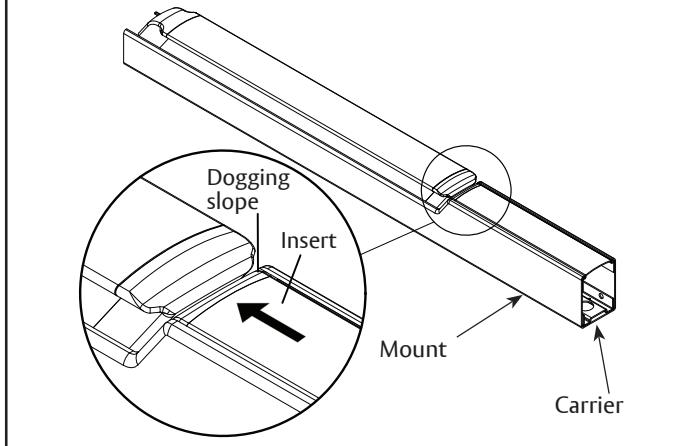
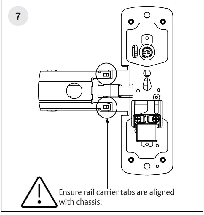
A. Ensure there isn't a gap between the insert and the dogging slope, and the carrier is fl ush with the mount.
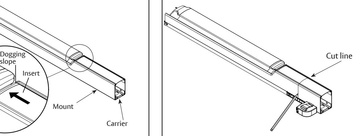
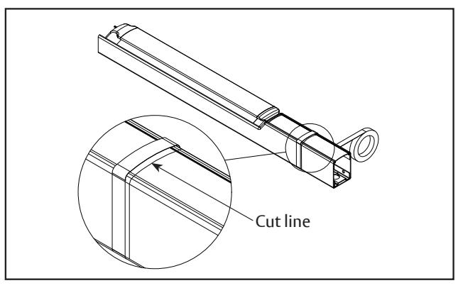
B. Mark rail at the required cut length.
Surface Vertical Rod Exit Device
Installation Instructions
Rail cutting guide, continued.

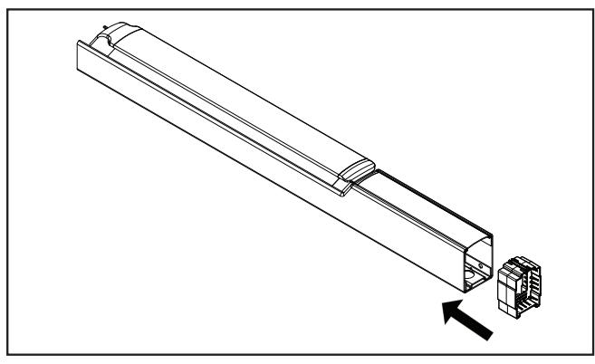
C. Ensure plastic insert support is installed under the cut line.
D. Wrap the rail and insert in masking tape, as shown.
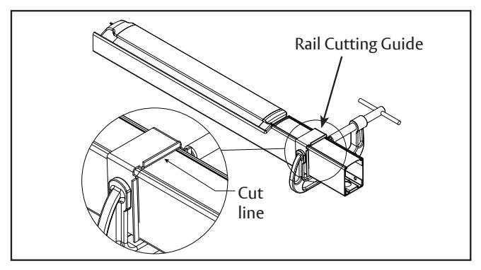
E. Place the rail cutting guide over the masking tape and align it with the cut line. Clamp the cut guide to the rail using a C-clamp.
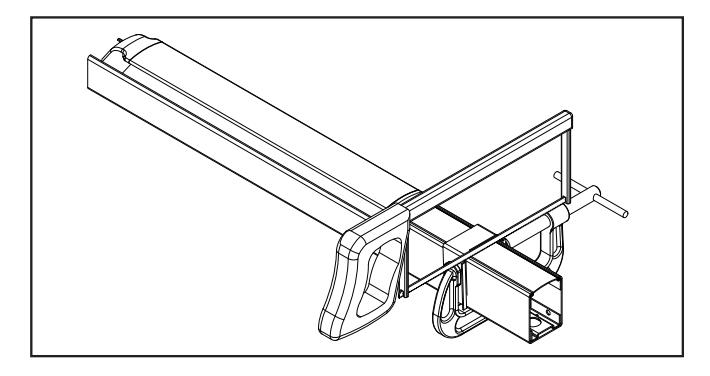
F. Using a hack saw with a new blade or a chop saw with a metal cutting blade, cut the rail, ensuring that the blade stays pressed against the rail cutting guide.
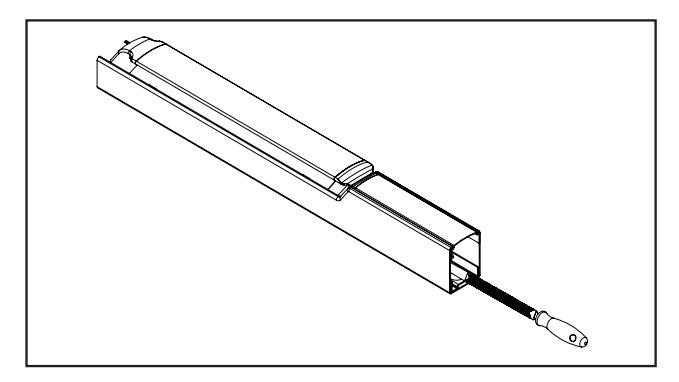
G. Deburr and smooth all cut edges with a fi le.
Surface Vertical Rod Exit Device

Surface Vertical Rod Exit Device
1-800-543-3658 • techsupport.corbinrusswin@assaabloy.com
Surface Vertical Rod Exit Device
Installation Instructions
Note: Top cases on fi re rated wood doors must be
place. Attach top case.
thru-bolted.
Surface Vertical Rod Exit Device
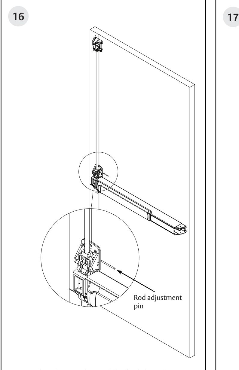
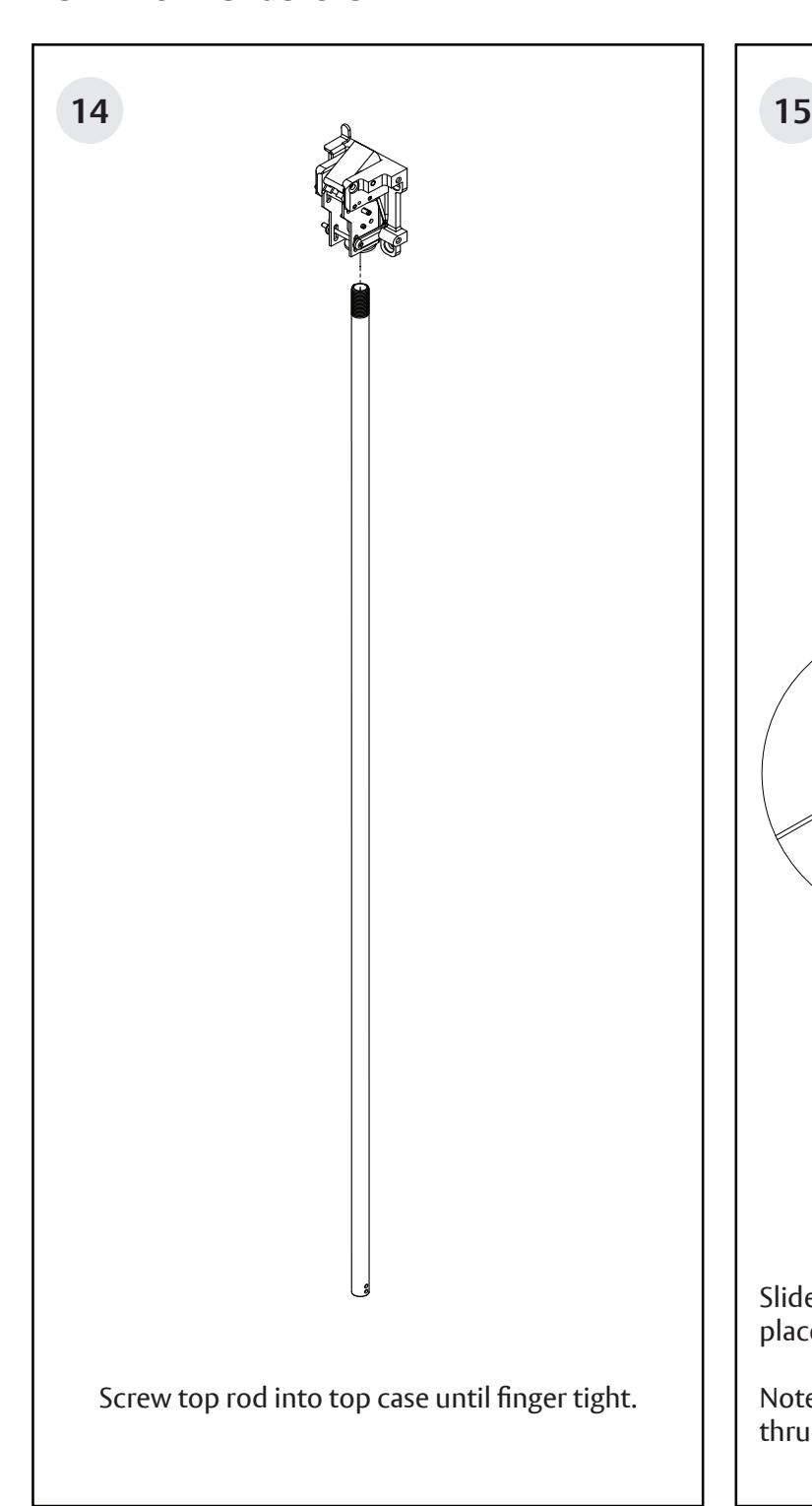
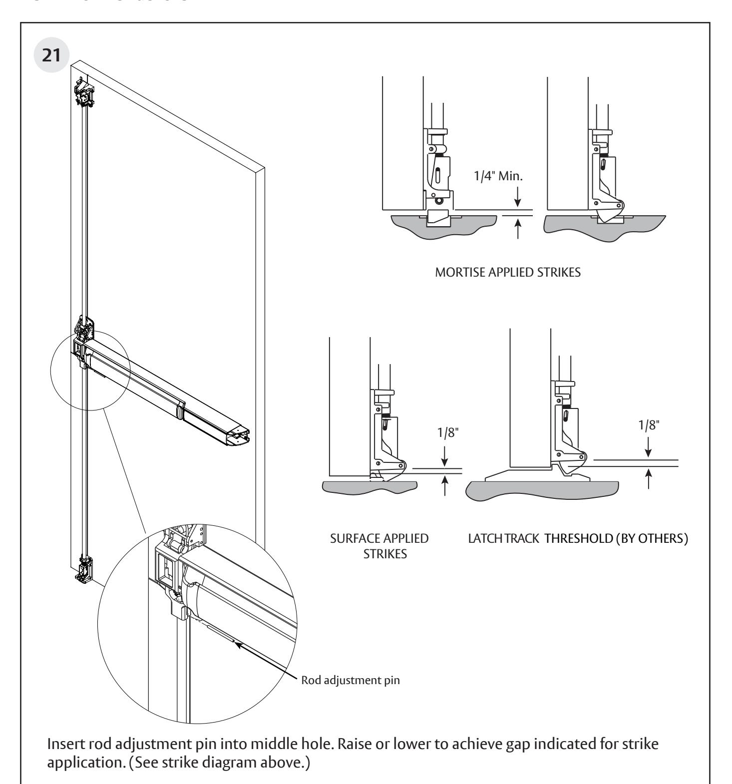
- Verify rail is not dogged (locked down).
- Unscrew top rod until the center hole is aligned with the hole in the main slide.
- Insert rod adjustment pin and align hole in rod with pin.
Surface Vertical Rod Exit Device

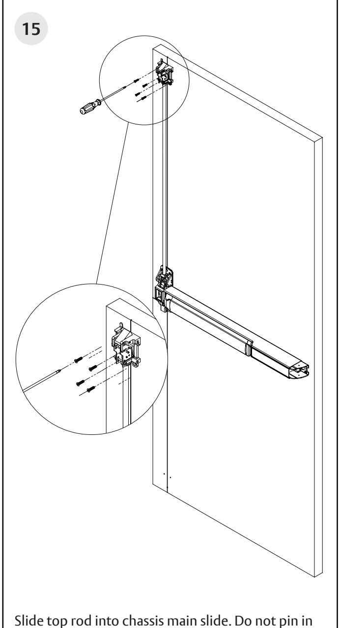
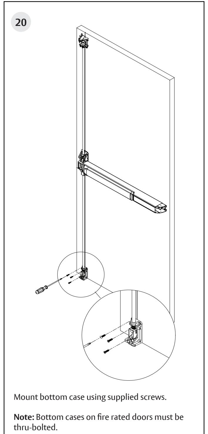
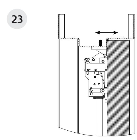
- Slide bottom rod into the chassis main slide.
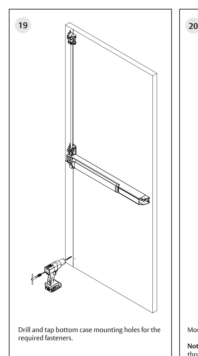
- Mark bottom case mounting holes based on the bottom case placement shown in image above.
Surface Vertical Rod Exit Device
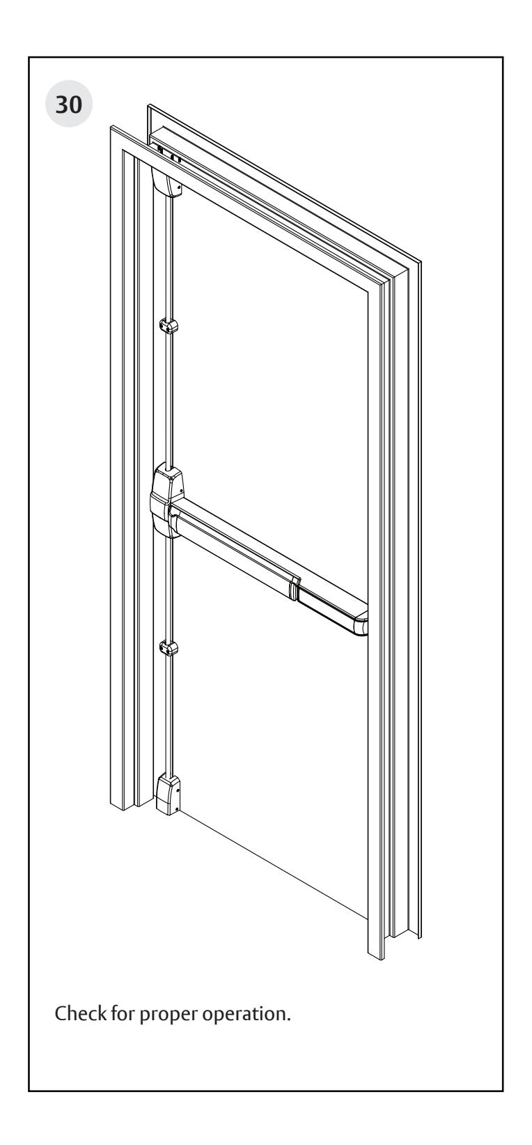
Surface Vertical Rod Exit Device
Surface Vertical Rod Exit Device
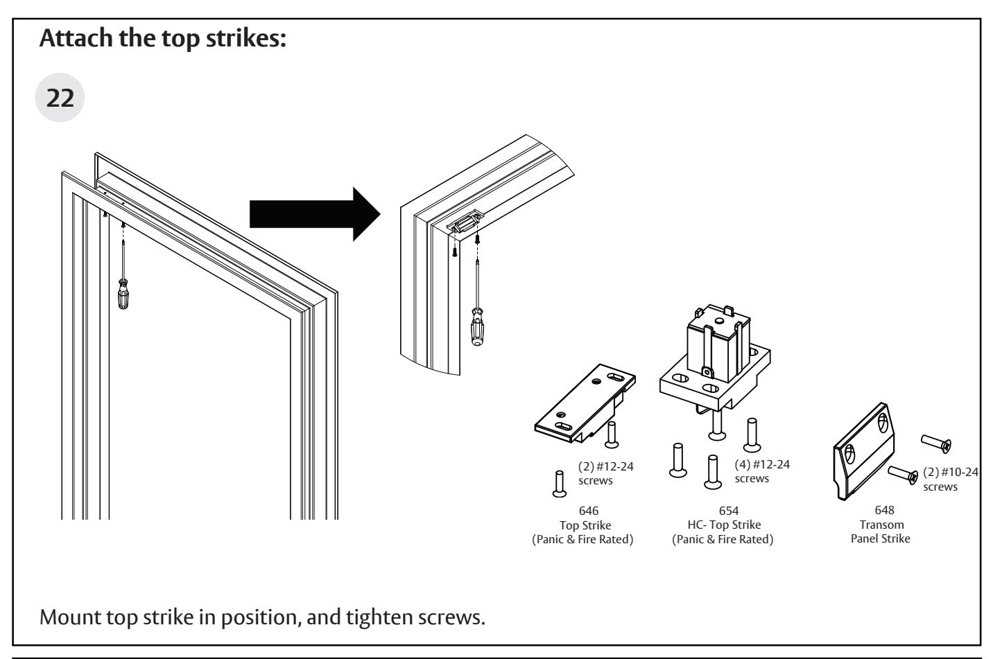
- Adjust the top strike, front to back using slots in strike.
- To increase engagement, shim the top strike.
Surface Vertical Rod Exit Device

Surface Vertical Rod Exit Device
Installation Instructions

Adjust top and bottom rods:

Fine adjustment is made by turning the rod into the top and bottom case to shorten or out of the top and bottom case to lengthen.
Rough adjustment is made by changing hole used for the adjustment pin.
Top Rod Adjustments:
- Push on door as you push on the rail assembly.
- As soon as the door opens, release rail. The top bolt should be in the hold back position.
- If not, extend top bolt.
Note: The top bolt must go into hold back position prior to the door opening.
Bottom Rod Adjustments:
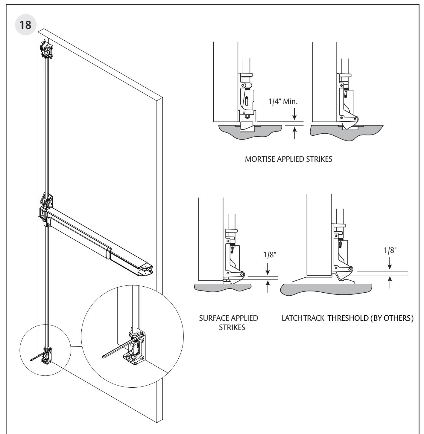
- Extend bottom bolt for maximum engagement with the bottom strike.
- When the top bolt is in, hold back, it also holds the bottom bolt in the retracted position.
- Always verify that when the bottom bolt is in the retracted position, the bolt clears the fi nished fl oor by at least 1/8" through the swing of the door.
Note: Both the top and bottom latch bolts must be adjusted for maximum engagement.
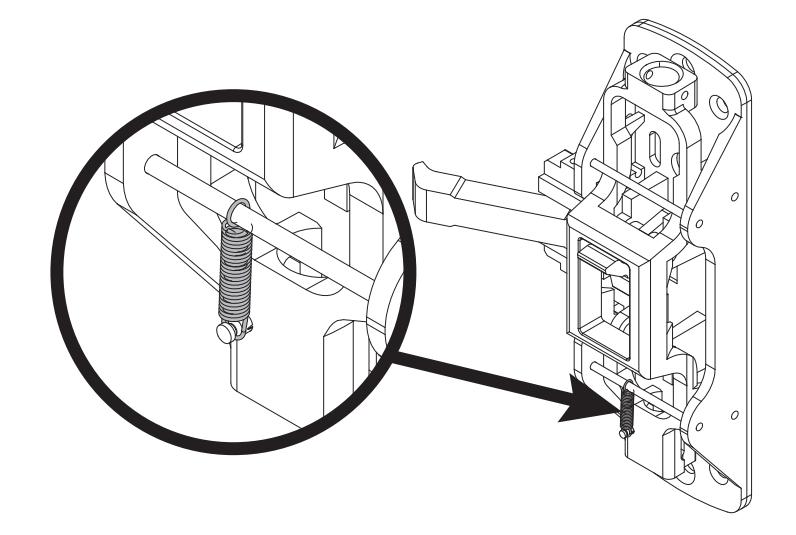
5CH Option
Once rods are adjusted, attach spring to groove pin on chassis main slide.
Note: Spring not required for less bottom rod devices (M55).
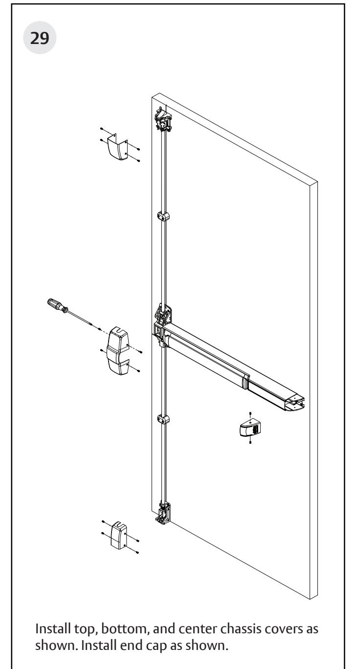
Surface Vertical Rod Exit Device

Surface Vertical Rod Exit Device
Installation Instructions

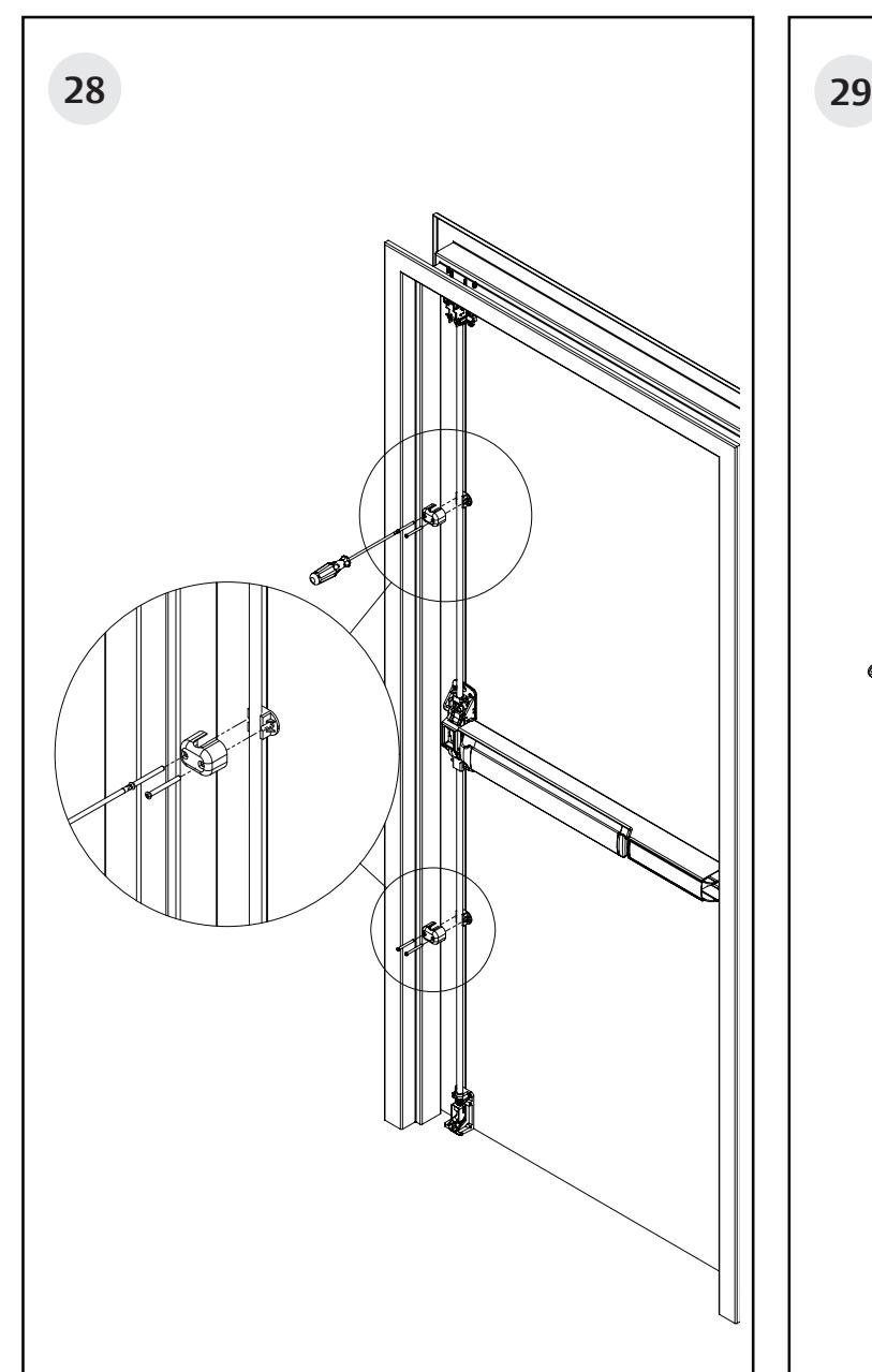
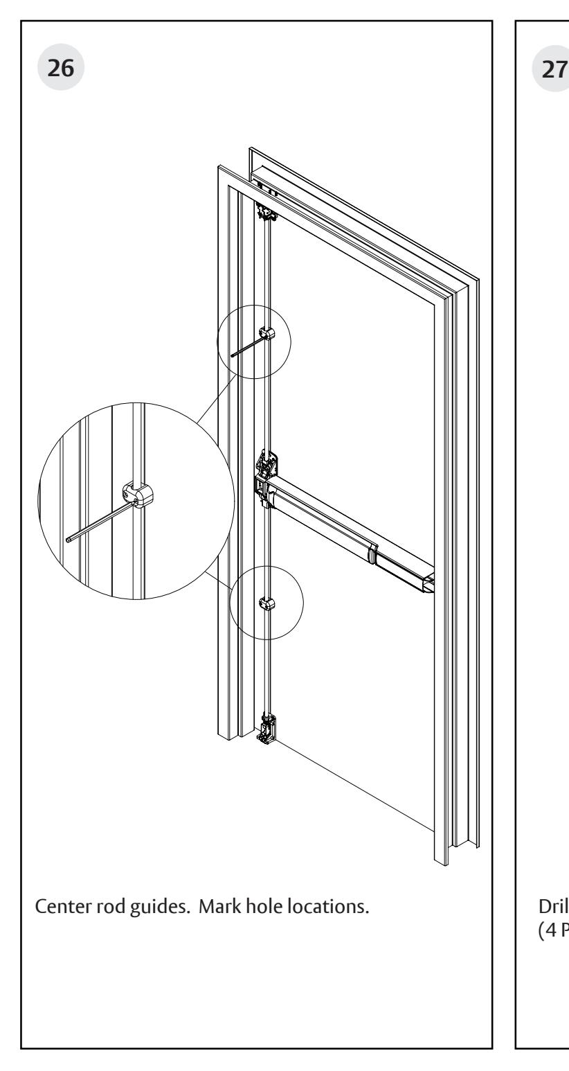
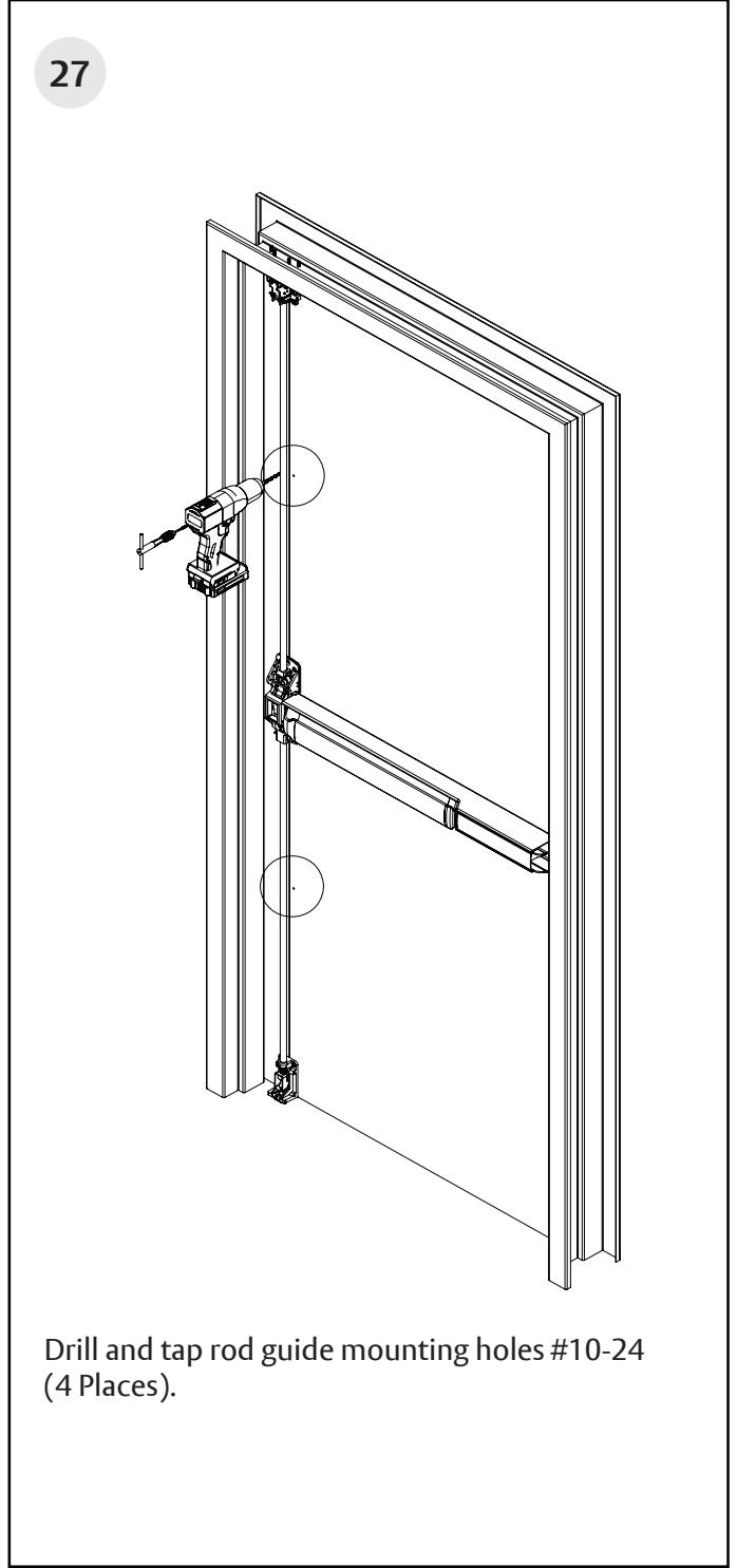
Install top and bottom rod guides. Rod must fl oat freely in guide without rubbing.
Note : For doors over 96": Install two (2) top rod guides equally spaced between the top case and the chassis cover.