Corbin Russwin PED5000 Series PED5400A(FE) Wide Stile SVR Installation Instructions_FM612
Open the original PDF document
View PDFInstallation Instructions

PED5400 FE & PED5400 A FE
Surface Vertical Rod Exit Devices

This product can expose you to lead which is known to the state of California to cause cancer and birth defects or other reproductive harm. For more information go to www. P65warnings.ca.gov.
1-800-543-3658 • techsupport.corbinrusswin@assaabloy.com
WARNING
Attention Installer: Improper installation may result in damage to the product and void the factory warranty.
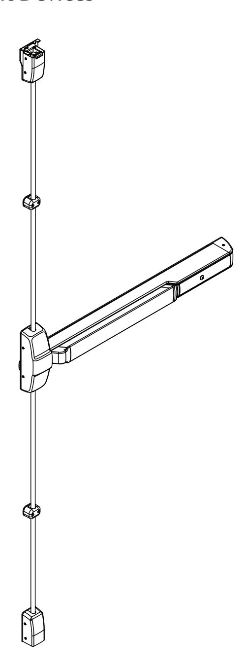
Surface Vertical Rod Exit Device
Installation Instructions
Screw Chart
| DESCRIPTION |
TOTAL QTY
SUPPLIED |
WHERE USED | |
|---|---|---|---|
|
#10-24 X 3/4" FLAT HEAD
MACHINE SCREW |
4 |
(4) CHASSIS
CORNER MOUNTING HOLES |
|
|
#10-24 X 3/4" ROUND HEAD
SOCKET SCREW |
2 | (2) REAR MOUNTING PLATE | |
|
#8-32 X 3/8" TRUSS HEAD
MACHINE SCREW |
2 | (2) CHASSIS TO MOUNT RAIL | |
|
#12-24 X 3/4" SOCKET HEAD
CAP SCREW WITH MORTISE NUT |
4 |
(2) TOP CASE
TOP MOUNTING HOLES (2) BOTTOM CASE BOTTOM MOUNTING HOLES |
|
|
#12-24 X 1" FLAT HEAD
SOCKET SCREW |
4 |
(2) TOP CASE
BOTTOM MOUNTING HOLES (2) BOTTOM CASE TOP MOUNTING HOLES |
|
|
#12-24 X 3/4" FLAT HEAD
MACHINE SCREW |
5 |
(1) TOP CASE SHIM
(4) 659 TOP LATCH STRIKE |
|
| RAIL RETAINER BOLT | 1 |
(1) MOUNT RAIL / CARRIER
TO DOOR |
|
| 1/4"-20 SHOULDER BOLT | 1 | (1) THRU INSERT | |
Surface Vertical Rod Exit Device
Installation Instructions
Screw Chart
| DESCRIPTION |
TOTAL QTY
SUPPLIED |
WHERE USED |
|---|---|---|
| 3 | (3) 653 BOTTOM STRIKE | |
|
1/4" SLEEVE ANCHOR
#10-24 X 1-1/2" OVAL HEAD MACHINE SCREW |
4 |
(2) TOP ROD GUIDE
(2) BOTTOM ROD GUIDE |
|
#8-32 X 5/16" W/ #6 OVAL HEAD
MACHINE SCREW |
12 |
(2) CHASSIS COVER
FRAME SIDE (2) END CAP (4) TOP CASE COVER (4) BOTTOM CASE COVER |
|
#8-32 X 5/8" W/ #6 OVAL HEAD
MACHINE SCREW |
2 |
(2) CHASSIS COVER
RAIL SIDE |
|
1/4"-20 X 2-3/8" KNURLED FLAT HEAD
MACHINE SCREW |
2 |
(2) EXIT TRIM
(IF USED) |
Surface Vertical Rod Exit Device
Installation Instructions
Tools Needed

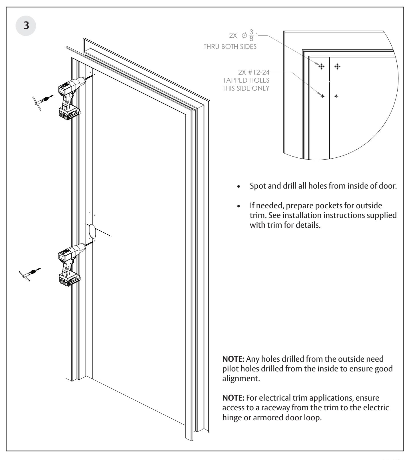
Before installation:
- 1. Install mullion, if used.
- 2. Fit and hang door.
- 3. Check the box's label for the size of the exit device.
Note: Please refer to trim and other installation instructions provided in the box.
The surface of the door where the exit device is to be applied must be flush. Clear away any raised projections to allow exit device to rest on the flat surface of the door. If shim kit is required, contact your distributor.
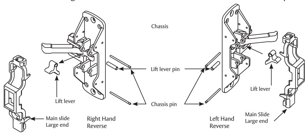
Handing
To Change Hand of a PED5401 Exit Device:
- 1. Remove both chassis pins and main slide.
- 2. Remove lift lever pin and lift lever.
- 3. Rotate chassis 180° and reposition lift lever and lift lever pin as shown below
- 4. Position main slide with large end of main slide at the bottom and retain with chassis pins.
INSIDE LEFT HAND REVERSE BEVEL RIGHT HAND REVERSE BEVEL THIS EXIT DEVICE IS HANDED CHECK HAND OF DEVICE AGAINST APPLICATION OUTSIDE
Surface Vertical Rod Exit Device
Installation Instructions

Product Overview
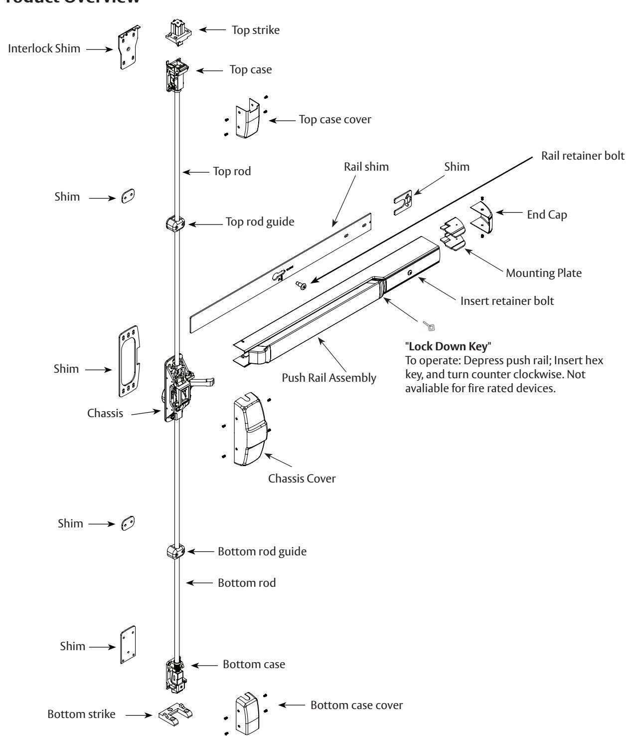
Surface Vertical Rod Exit Device
Installation Instructions

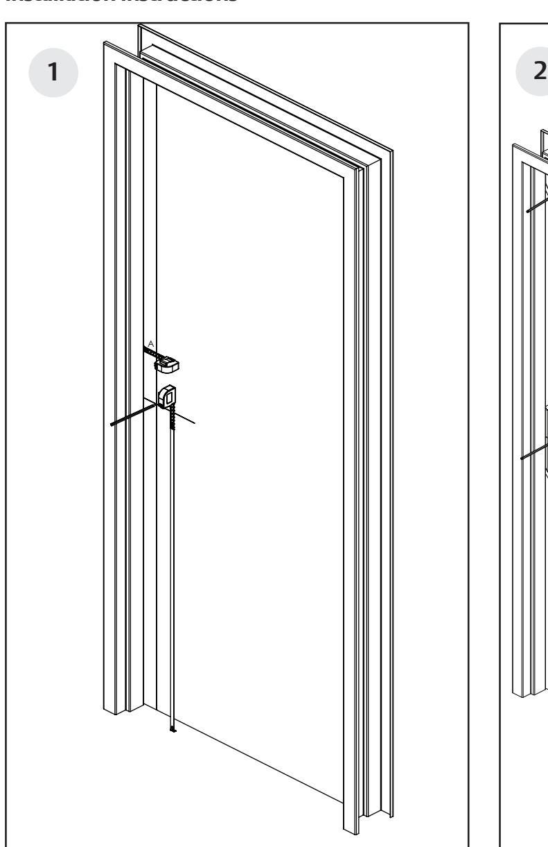
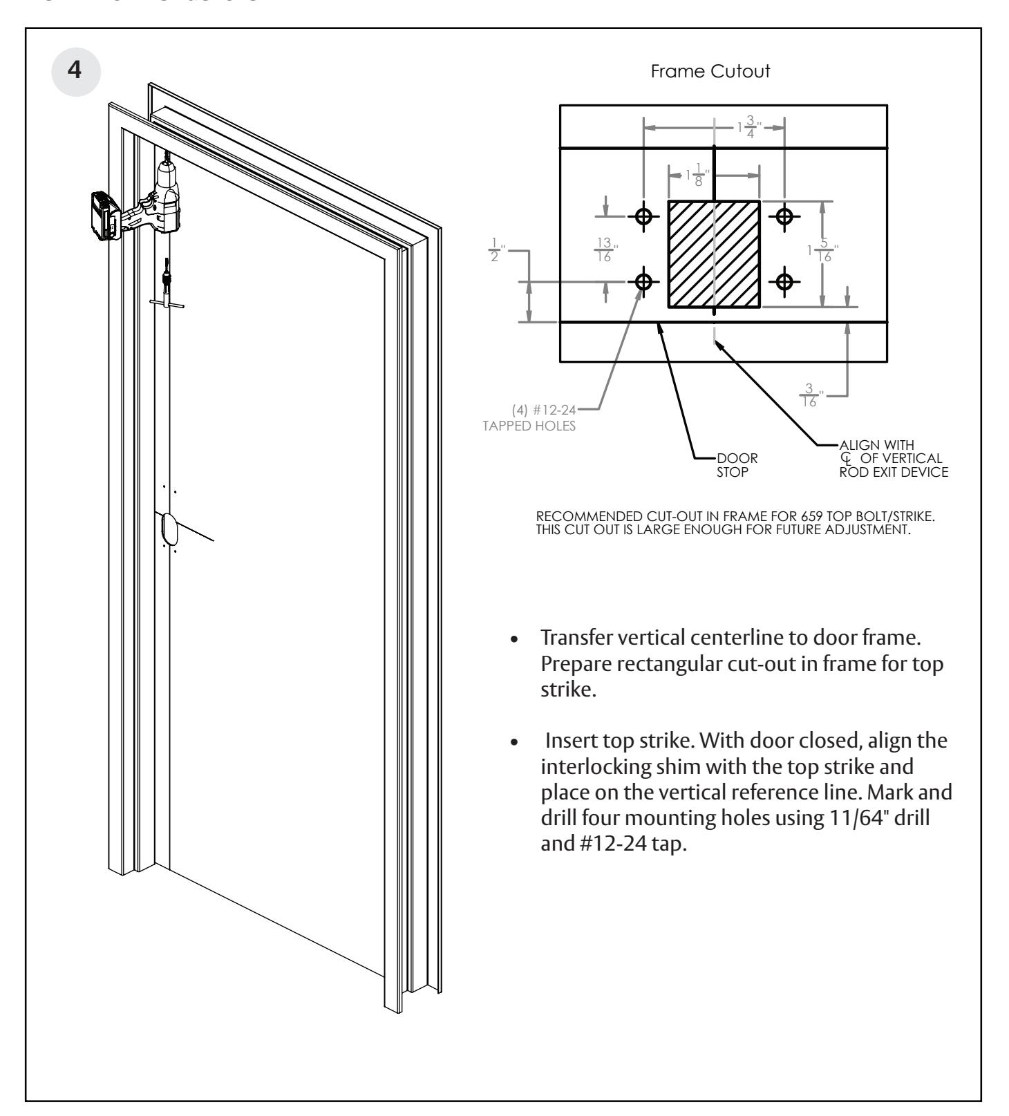
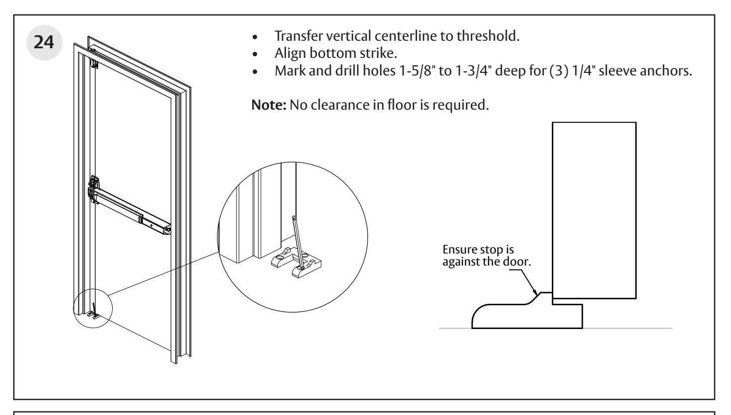
- With door closed, measure and mark 2-3/4" to locate the vertical reference center line of the chassis, top case, and bottom case.
- Horizontal reference line is rail centerline height. Standard rail centerline height is 39- 5/8" above the finished floor.
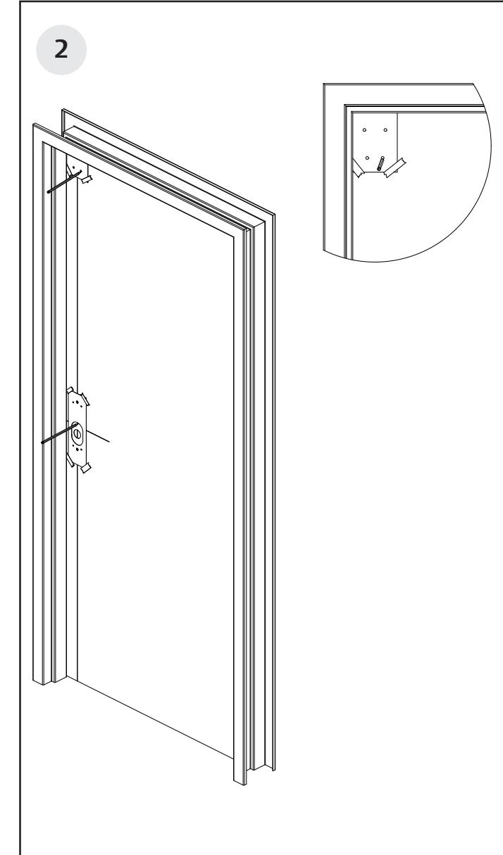
- With door closed, tape template for chassis / trim on inside of door, along vertical and horizontal reference lines.
- Fold top case / top strike template and tape on inside of door along vertical reference lines.
Surface Vertical Rod Exit Device
Installation Instructions

pending and/or patent www.assaabloydss.com/patents.
Copyright © 2023, ASSA ABLOY Access and Egress Hardware Group, Inc. All rights reserved. Reproduction in whole or in
Surface Vertical Rod Exit Device

Installation Instructions
Surface Vertical Rod Exit Device
Installation Instructions

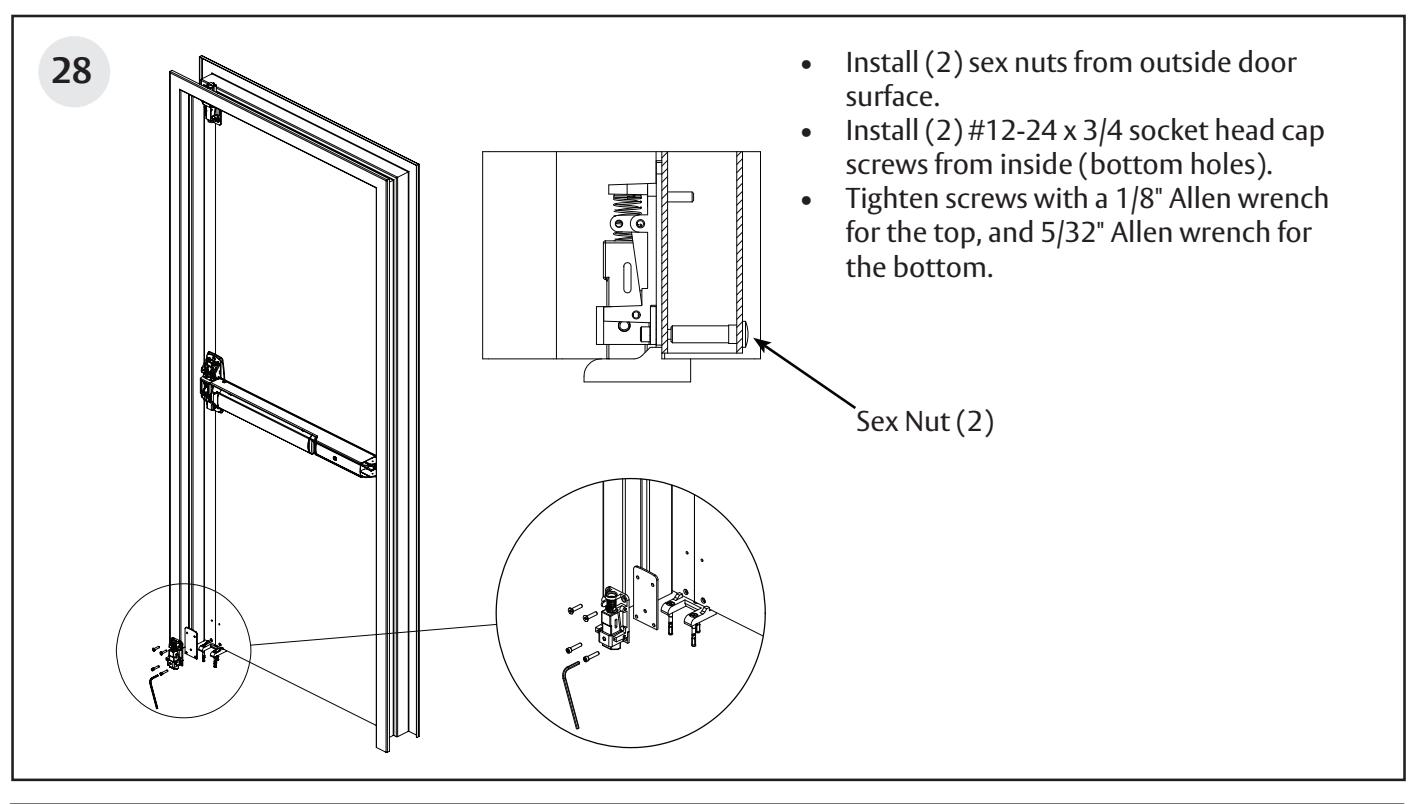
Mount top strike, (4) #12-24 x 3/4" phillips flat head machine screws. Flat side of top bolt should be facing away from the door.
Note : All four fasteners required. DO NOT TIGHTEN FULLY.
9
Surface Vertical Rod Exit Device
Installation Instructions
pending and/or patent www.assaabloydss.com/patents.
Surface Vertical Rod Exit Device
Installation Instructions
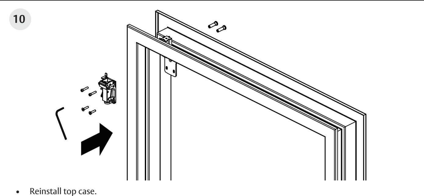
• Tighten all screws.
• Check for top case and top strike engagement.
Surface Vertical Rod Exit Device
Installation Instructions

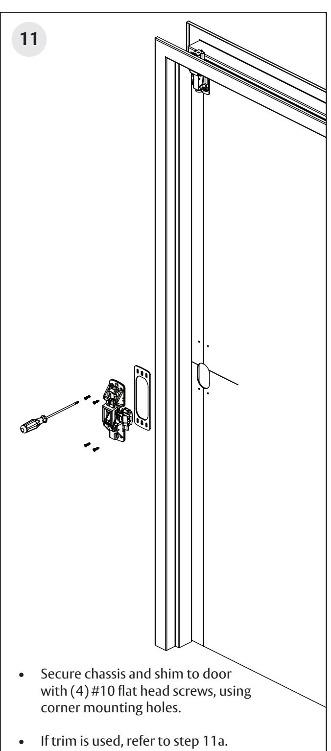
Position ET trim on door. Align spindle with bell housing. Thru-bolt chassis to ET trim with (2) 1/4-20 flat head screws. 11a 800PT and 900PT Series ET Trim Chassis PT Series Trim
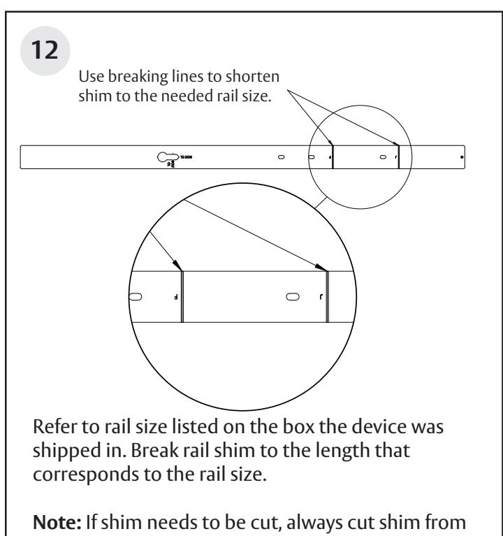
the end closest to the hinge edge.
Surface Vertical Rod Exit Device
Installation Instructions

Rail cutting guide
If the rail doesn't need to be cut, continue to page 15, step 13. If the rail must be cut, follow these steps on page 13 and 14:
Refer to the individual exit device installation instructions for rail cutting requirements / restrictions. Instructions will vary based on device type and options.
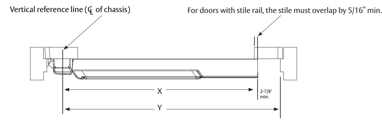
• Determine cut off dimension "X" by subtracting 2-7/8" from dimension "Y". Mark cut off point on mounting rail. (See below.)
Do not cut closer than 1-5/8" from the the front edge of the rail insert.
| Information for Cutting Rails | |||
|---|---|---|---|
| Door Widths | |||
| Rail Sizes | Standard | ||
| W036 (Std.) | 36" | ||
| W042 | 42" | ||
| W048 | 48" | ||
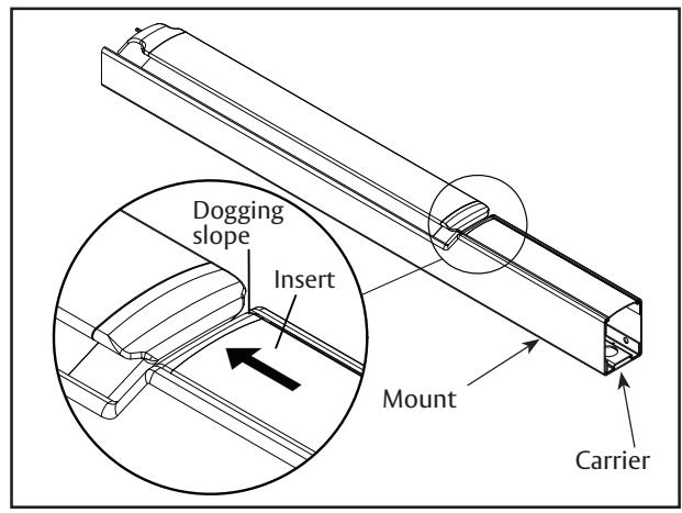
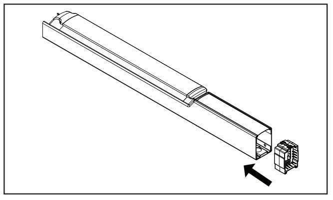
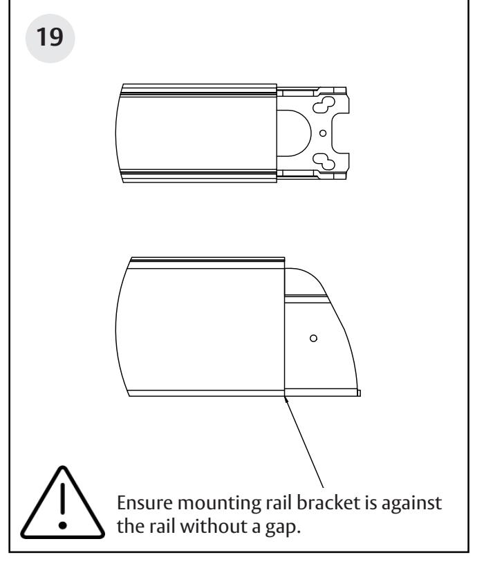
A. Ensure there isn't a gap between the insert and the dogging slope, and the carrier is flush with the mount.
1-800-543-3658 • techsupport.corbinrusswin@assaabloy.com
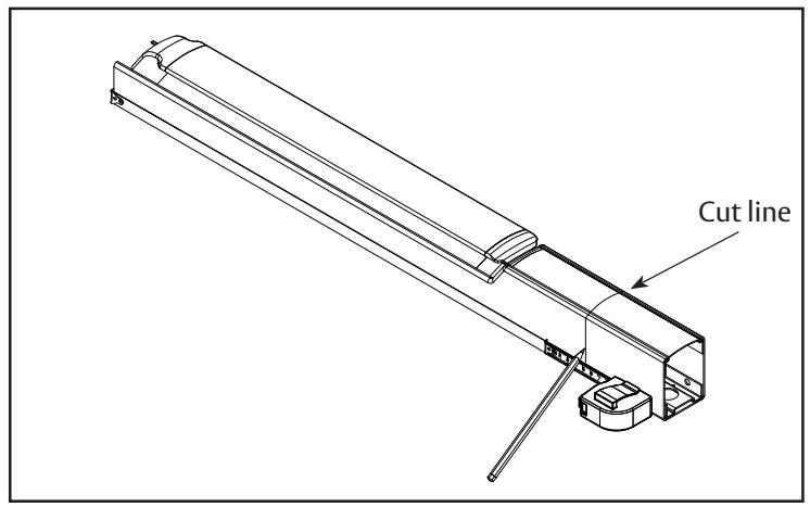
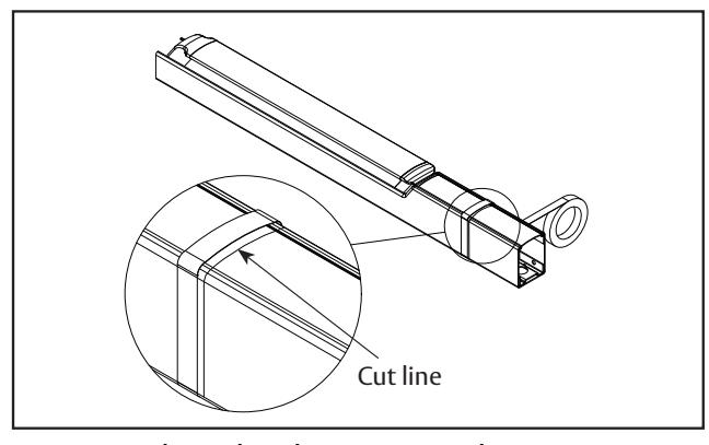
B. Mark rail at the required cut length.
Surface Vertical Rod Exit Device
Installation Instructions
Rail cutting guide, continued.
C. Ensure plastic insert support is installed under the cut line.
D. Wrap the rail and insert in masking tape, as shown.
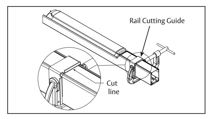
E. Place the rail cutting guide over the masking tape and align it with the cut line. Clamp the cut guide to the rail using a C-clamp.
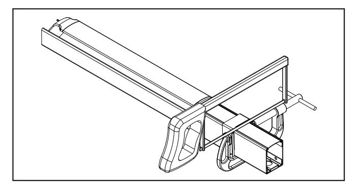
F. Using a hack saw with a new blade or a chop saw with a metal cutting blade, cut the rail, ensuring that the blade stays pressed against the rail cutting guide.
G. Deburr and smooth all cut edges with a file.
Surface Vertical Rod Exit Device

Surface Vertical Rod Exit Device
Installation Instructions

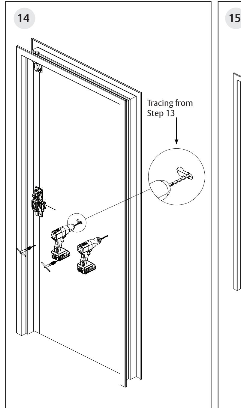
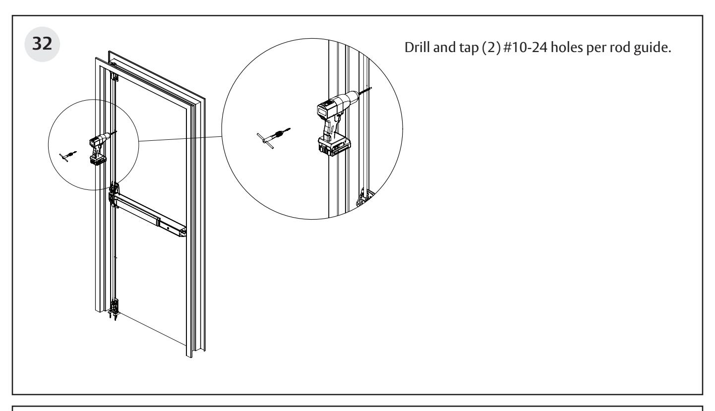
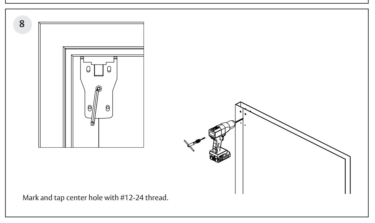
Remove rail shim from door to expose tracing. Drill and tap (2) holes as shown in door surface. ("I" drill with 5/16-24 tap for hole at the middle of the door, #7 drill with 1/4-20 tap for hole closer to hinge.
Surface Vertical Rod Exit Device
Installation Instructions

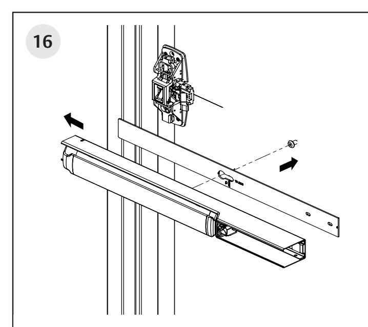
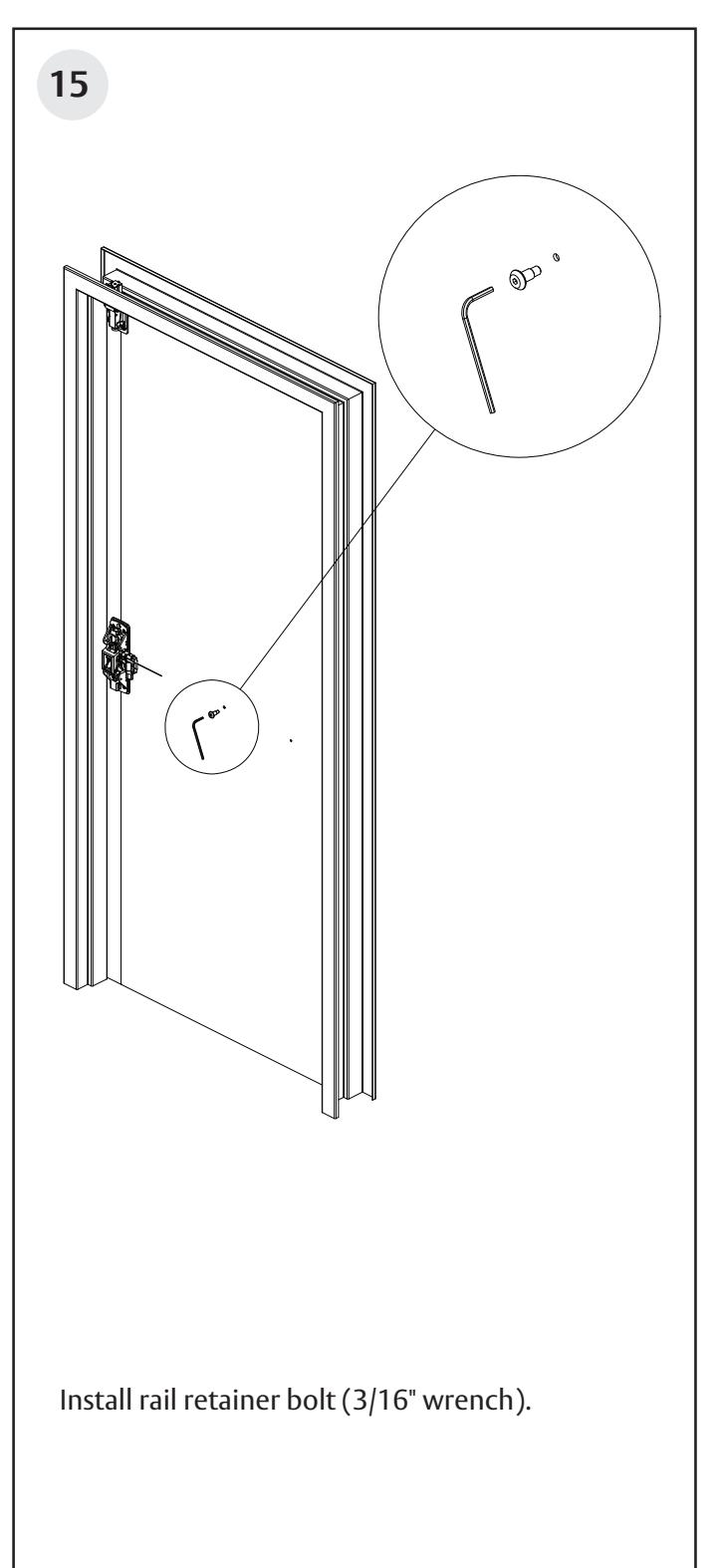
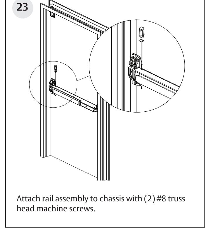
Depress chassis lift arm, and slide rail assemby with rail shim onto chassis. Ensure rail retainer bolt engages properly with slot in rail shim and rail assembly.
1-800-543-3658 • techsupport.corbinrusswin@assaabloy.com
with shim.
FM612 01/23
Surface Vertical Rod Exit Device
Installation Instructions

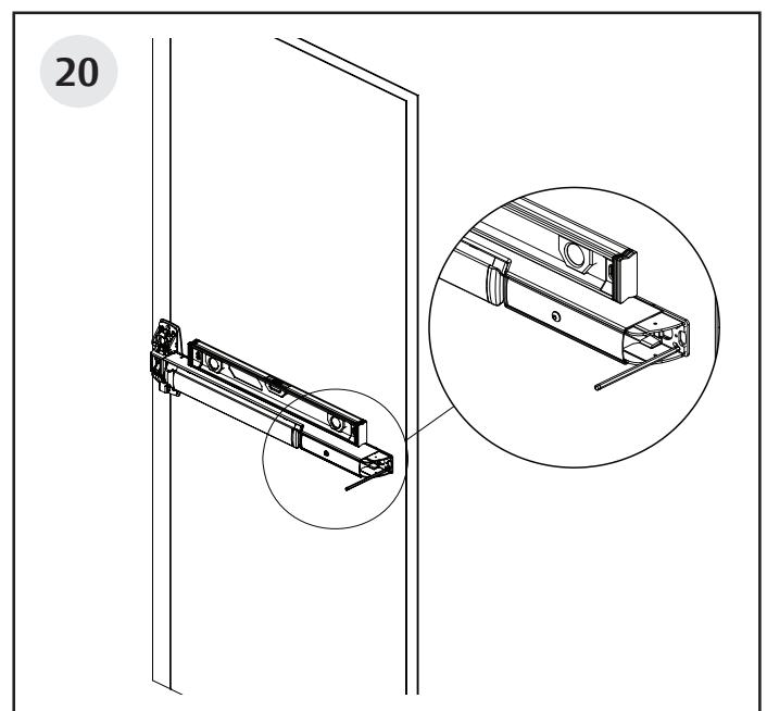
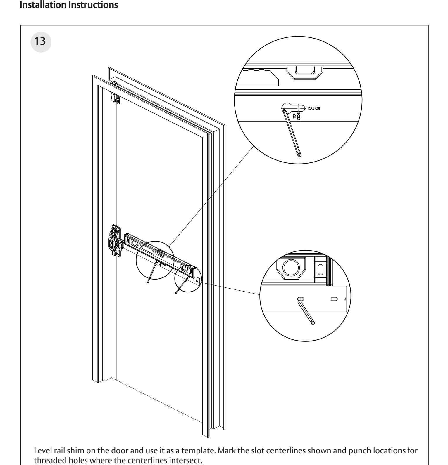
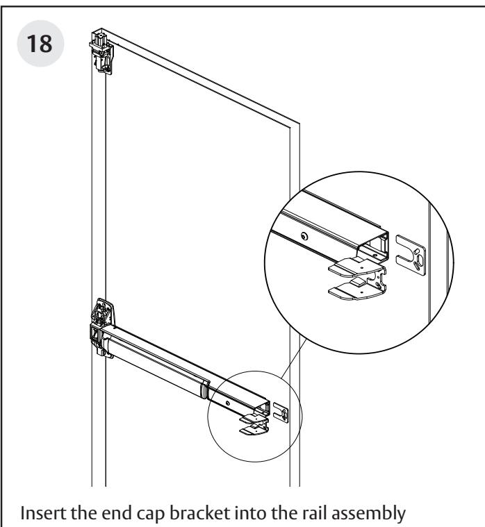
Verify the rail is level and mark mounting holes, using the bracket as a guide.
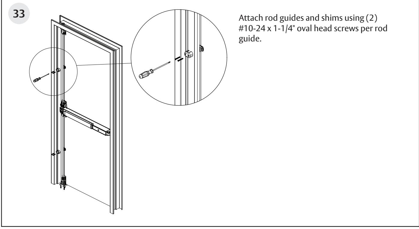
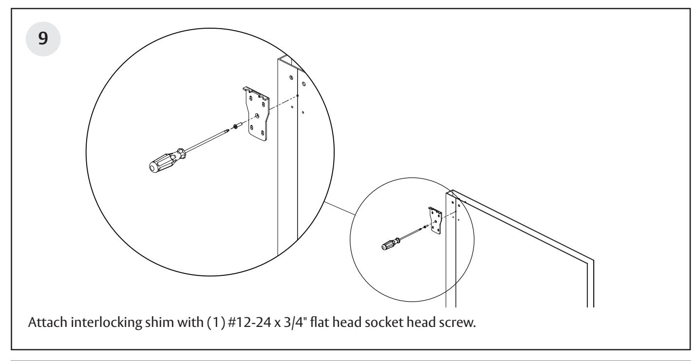
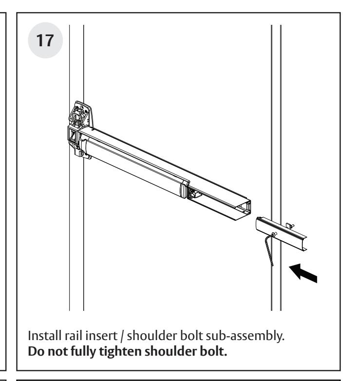
#10-24 x 3/4" screws, supplied. Tighten the insert
shoulder bolt.
Surface Vertical Rod Exit Device
Installation Instructions

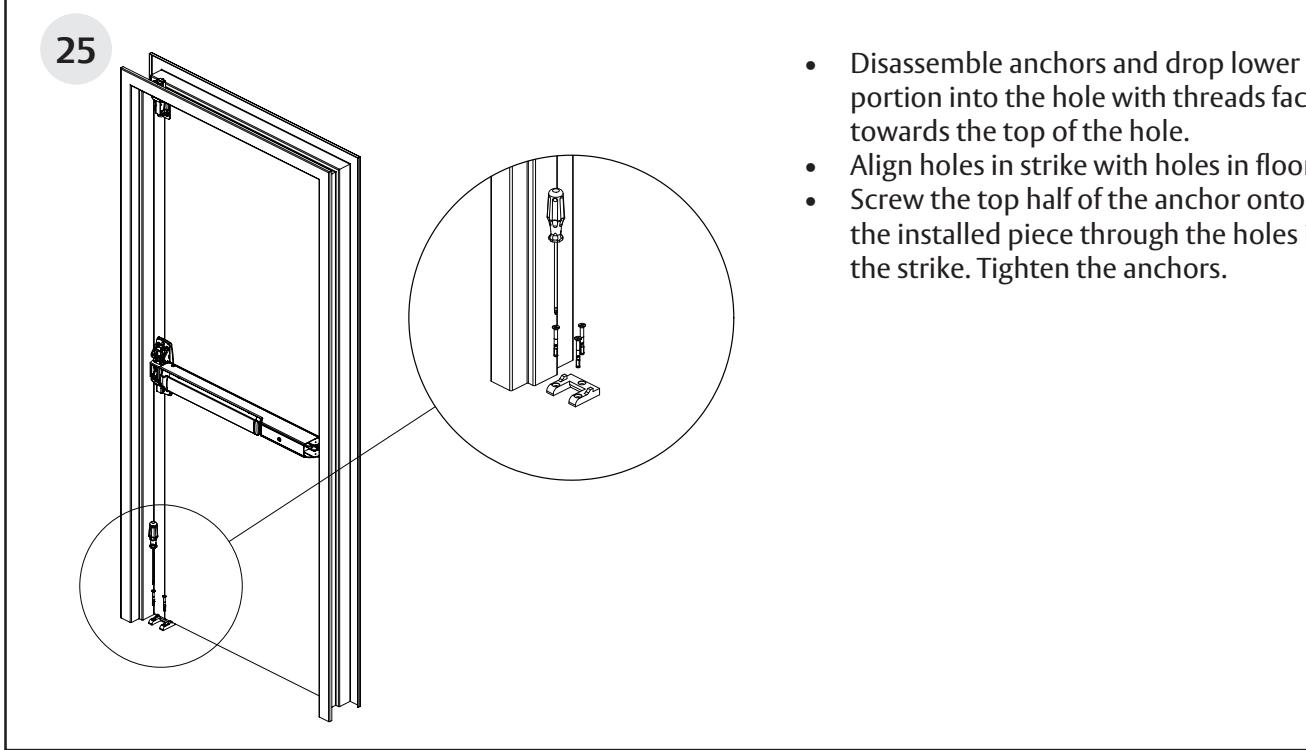
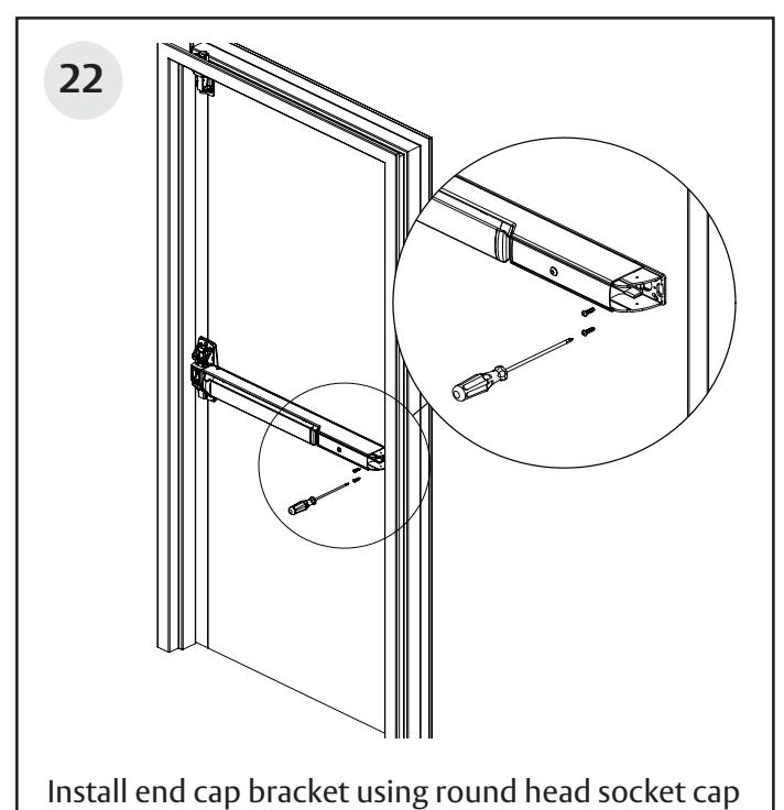
- portion into the hole with threads facing towards the top of the hole.
- Align holes in strike with holes in floor.
- Screw the top half of the anchor onto the installed piece through the holes in the strike. Tighten the anchors.
1-800-543-3658 • techsupport.corbinrusswin@assaabloy.com
Surface Vertical Rod Exit Device
Corbin Z
Installation Instructions
Surface Vertical Rod Exit Device
Installation Instructions

pending and/or patent www.assaabloydss.com/patents.
Copyright © 2023, ASSA ABLOY Access and Egress Hardware Group, Inc. All rights reserved. Reproduction in whole or in part without the express written permission of ASSA ABLOY Access and Egress Hardware Group, Inc. is prohibited. Patent
21
Surface Vertical Rod Exit Device
Installation Instructions

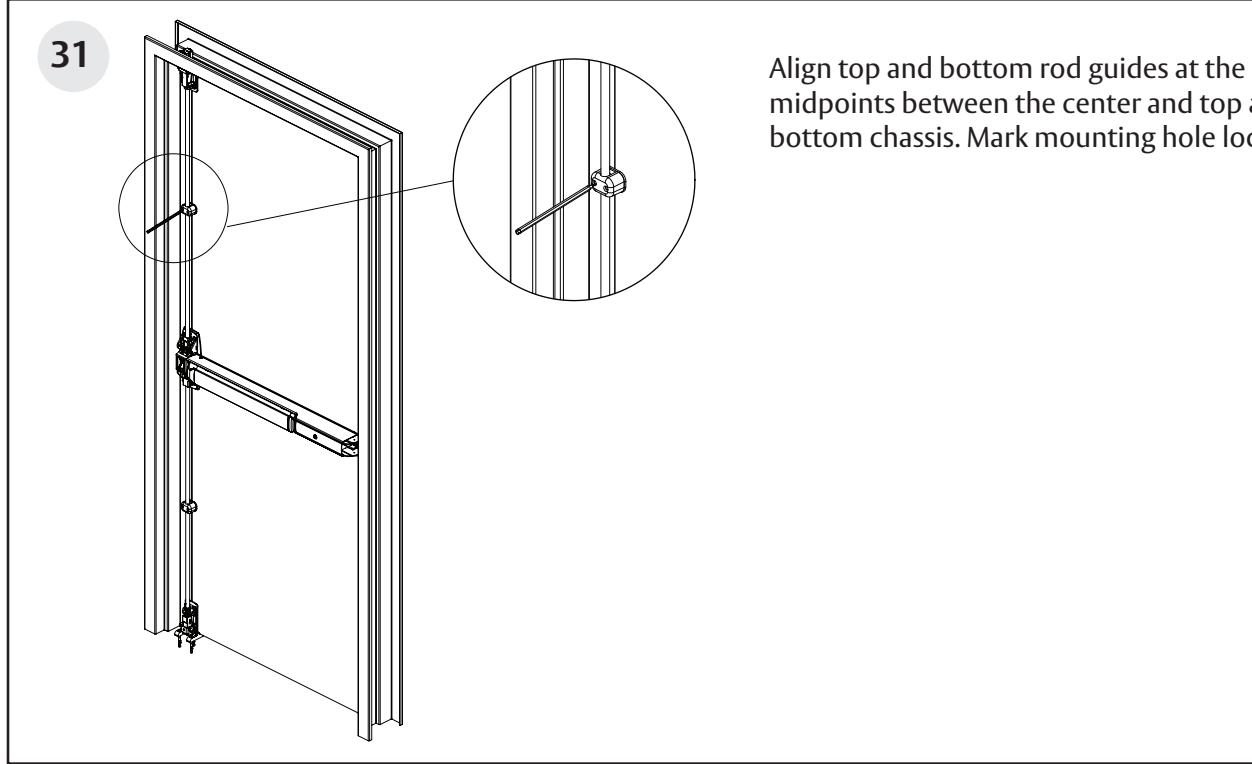
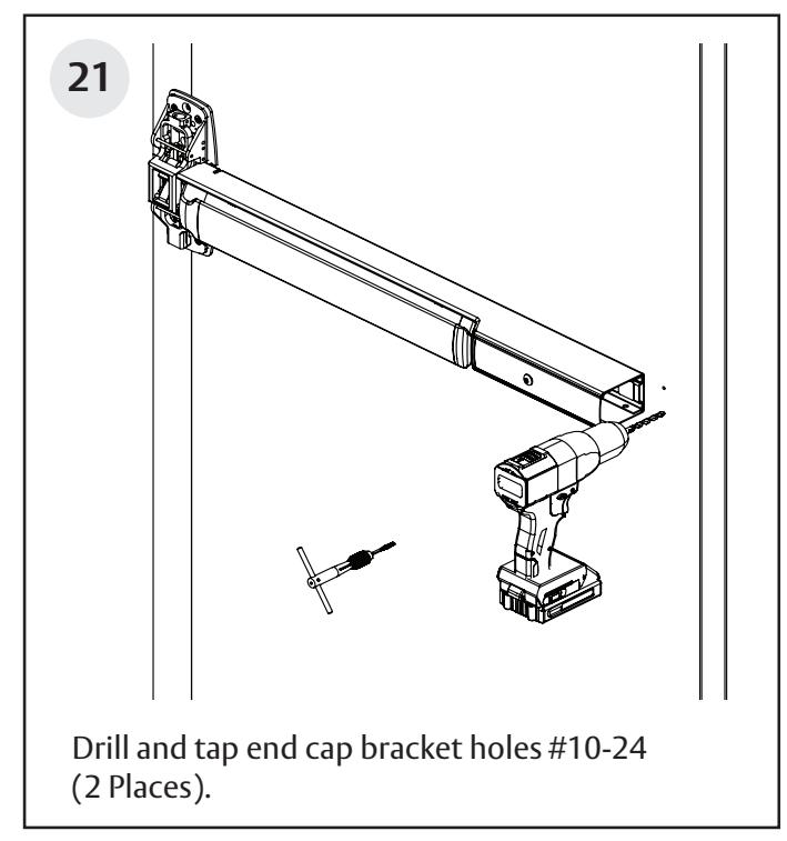
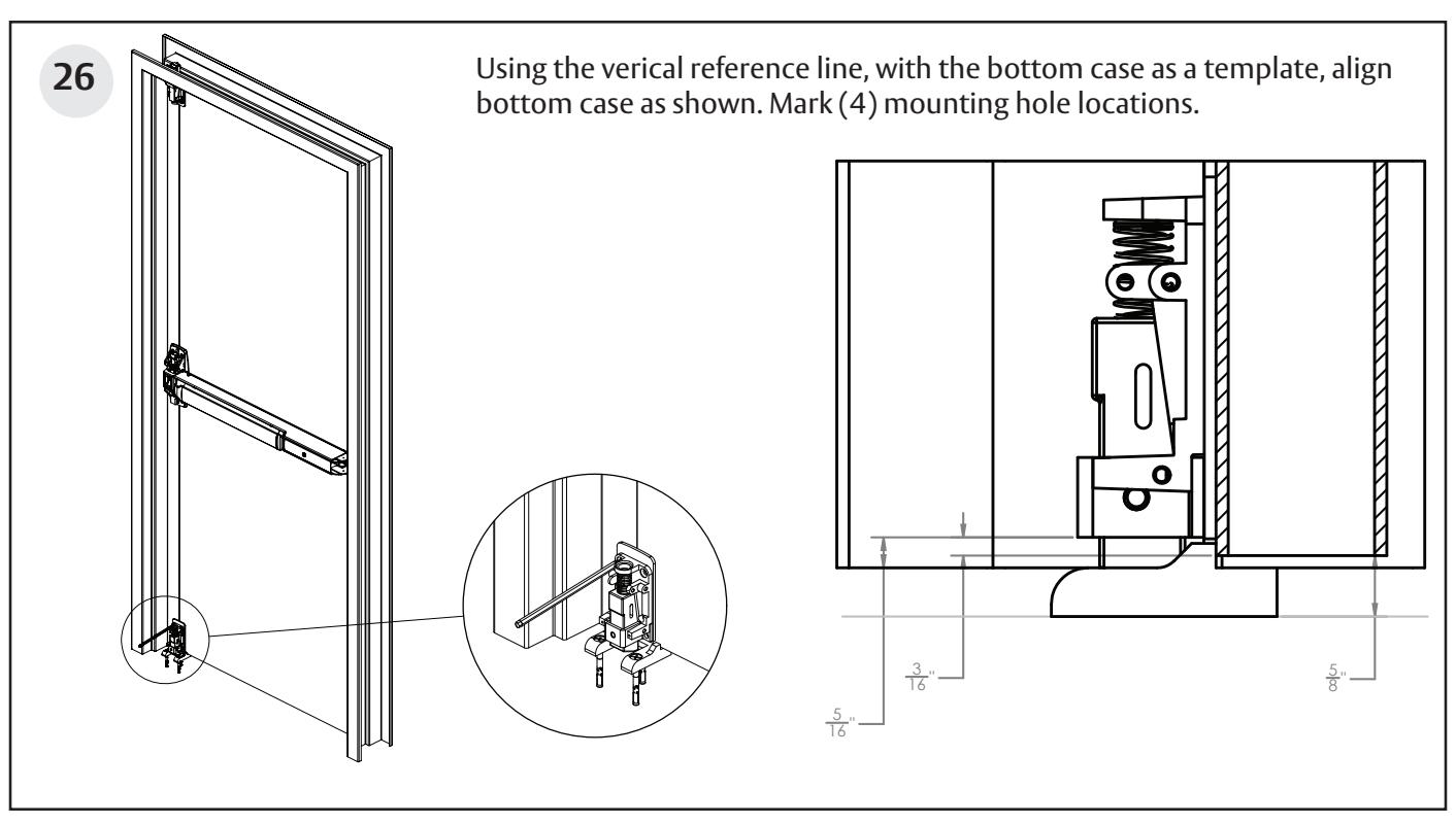
midpoints between the center and top and bottom chassis. Mark mounting hole locations.
Surface Vertical Rod Exit Device
Installation Instructions